Celtic Interconnector - Route Options Review In the Vicinity of Churchtown March 2021 - EirGrid
←
→
Page content transcription
If your browser does not render page correctly, please read the page content below
Celtic Interconnector

   Route Options Review
In the Vicinity of Churchtown

        March 2021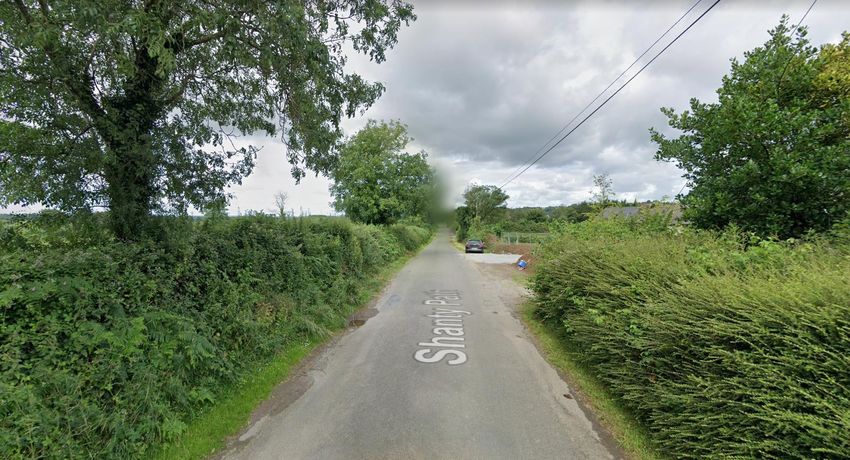
Table of Contents
EXECUTIVE SUMMARY ....................................................................................................... 3
1. Introduction .................................................................................................................. 5
1.1 Project Overview ...................................................................................................... 5
1.2 Project Development................................................................................................ 5
1.3 Purpose and Scope of this Route Options Review ................................................... 7
2. Approach and Methodology ...................................................................................... 16
2.1 Multi Criteria Analysis (MCA) ................................................................................. 16
2.2 The Performance Matrix......................................................................................... 17
3. Relevant Matters of Construction and Operation .................................................... 18
3.1 The Appointed Contractor ...................................................................................... 18
3.2 Cable Route Installation Schedule ......................................................................... 19
3.3 Underground Cable Construction ........................................................................... 19
3.4 Other Matters ......................................................................................................... 28
4. EMF and DC Underground Cables ............................................................................ 29
4.1 Introduction ............................................................................................................ 29
4.2 EMF and Underground Cables............................................................................... 32
4.3 EMF Policy and Guidance...................................................................................... 33
4.4 EMF and the Celtic Interconnector ......................................................................... 34
4.5 EMF and the Precautionary Principle ..................................................................... 34
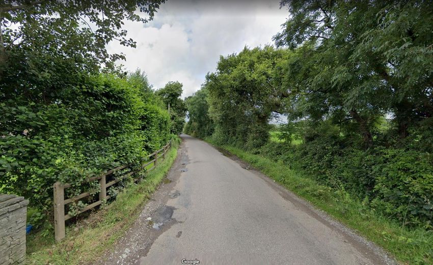
5. Option A – Local Road Route (Shanty Path) ............................................................ 35
5.1 Original Consideration ........................................................................................... 35
5.2 Route Options Review – Description of the Existing Development Context ............ 35
5.3 Route Options Review – Multi-Criteria Evaluation .................................................. 40
6. Option B – Disused Railway Corridor / Greenway Route ........................................ 44
6.1 Original Consideration ........................................................................................... 44
6.2 Route Options Review – Description of the Existing Development Context ............ 45
6.3 Route Options Review – Multi-Criteria Evaluation .................................................. 52
7. Option C – N25 west of Midleton ............................................................................... 56
7.1 Original Consideration ........................................................................................... 56
7.2 Route Options Review – Description of the Existing Development Context ............ 56
7.3 Route Options Review – Multi-Criteria Evaluation .................................................. 61
8. Option D – Midleton ................................................................................................... 67
8.1 Original Consideration ........................................................................................... 67
8.2 Route Options Review – Description of the Existing Development Context ............ 67
8.3 Route Options Review – Multi-Criteria Evaluation .................................................. 72
9. Option E – Typical Off-Road (Cross Country) Option .............................................. 76
9.1 Original Consideration ........................................................................................... 76
9.2 Route Options Review – Description of the Existing Development Context ............ 76
9.3 Route Options Review – Multi-Criteria Evaluation .................................................. 79
10. Conclusion – Comparative Evaluation.................................................................. 83
2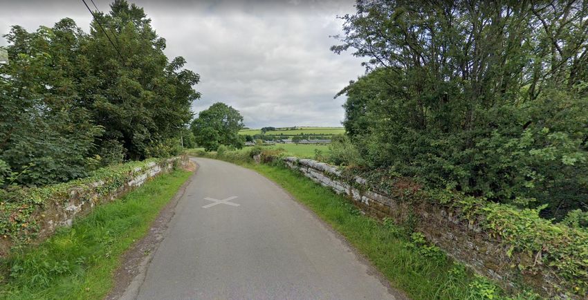
EXECUTIVE SUMMARY
The Celtic Interconnector is a subsea link that will enable the exchange of electricity
between the electrical transmission grids in Ireland and France. The key elements of the
project onshore in Ireland comprise:-
A landfall at Claycastle Beach, Youghal, Co. Cork;
A High Voltage Direct Current (HVDC) Underground Cable (UGC) between Claycastle,
and a converter station, to be sited at the Industrial Development Agency (IDA)
landholding at Ballyadam, east of Carrigtohill;
A converter station at Ballyadam, to convert HVDC electricity to High Voltage
Alternating Current (HVAC), as used on the Irish electricity grid, and vice versa;
A HVAC UGC between the Ballyadam converter station and the grid connection point
at the existing Knockraha substation, near Watergrasshill, Co. Cork.
The Irish onshore elements of the project have been developed in accordance with EirGrid’s
six-step Framework for Grid Development. The project is now in Step 5 of the process,
where an identified “Best Performing Option” forms the focus for technical and environmental
assessment. This will culminate with submission of applications for Statutory consent.
This Route Options Review concerns the area and environs of Churchtown, between
Castlemartyr and Midleton, Co. Cork. The Review comprises a focused description and a
comparative evaluation of the various alternative HVDC UGC route options in this area. The
undertaking of this Review fulfils a commitment to the Churchtown Residents Group (CRG).
This Review has been undertaken by a team of Technical, Environmental, Ecological,
Planning, Engineering, Agricultural and other specialists in EirGrid, having regard to both
issues and concerns raised by the CRG, and in engagement with representatives from key
stakeholders such as Cork County Council (CCC), Iarnród Eireann (IE), Transportation
Infrastructure Ireland (TII), and the Cork Roads Design Office (RDO).
There are 5 main HVDC UGC alternatives that are considered in this report:
The Churchtown Road (Shanty Path) and local roads;
The disused Midleton-Youghal railway corridor;
The existing N25 corridor extending west of Midleton;
The built-up area of Midleton;
Typical off-road / cross-country options in the vicinity of Churchtown.
These route alternatives are qualitatively evaluated by reference to Technical, Economic,
Environmental, Socio-Economic and Deliverability criteria, as well as having regard to public
and stakeholder engagement and feedback.
Following consenting, construction of the project will be undertaken by an appointed
Contractor who will prepare a detailed design of the development – exactly where the cable
will be laid within the consented area, and any other specific matters for its construction and
installation. In consultation with EirGrid, the Contractor will also prepare a detailed
3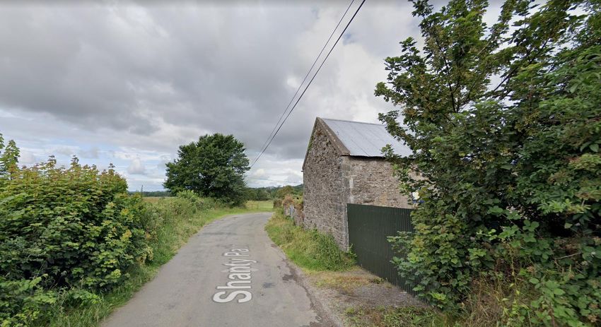
Construction Environmental Management Plan (CEMP), Traffic Management Plan (TMP),
Waste Management Plan, other Management Plans and/or associated Method Statements.
The laying of UGC is a standard construction technique undertaken by a range of utility and
other services providers. On public roads, traffic control measures will be implemented as
appropriate, including road diversions, closures and stop / go traffic management. Joint bays
(underground chambers) are used to pull various lengths of UGC through pre-installed ducts
and to connect (“joint”) together those lengths of UGC into a single overall circuit. Off-road
passing bays, constructed adjacent to a joint bay, facilitates the through movement of traffic.
For off-road UGC laying, a working area of approximately 30 metres is required, with a
permanent strip of 14 metres required to be kept free from obstruction or vegetation that
could potentially damage the UGC or restrict access to it over the course of its operation.
The HVDC UGC will generate a static magnetic field. These fields are called
Electromagnetic Fields (EMFs). To avoid any potential public risk in close proximity to
electrical infrastructure, national and international health and regulatory authorities have
recommended exposure limits for EMFs. It is EirGrid’s policy to design and operate the
electricity transmission system such that these limits are not exceeded. The static magnetic
field directly over the HVDC UGC, when the cable is at maximum circuit loading, is predicted
to be comparable with the naturally occurring earth’s magnetic field. This is multiples lower
than the recommended continuous exposure limit set out in international guidelines.
The Review concludes that the Churchtown Road route option is the Best Performing Option
of the various alternatives for the following reasons:-
From a Technical perspective, the option is not unduly complex in comparison with the
other options; avoidance of impact on an existing watermain within the road is a
standard matter of detailed design and construction methodology;
From an Economic perspective, the option is of generally greater length in comparison
with the other options; however, its relatively straightforward construction relative to
the other options is likely to result in equal or lower overall construction costs;
From an Environmental perspective, the option is laid within the public road, within an
area that has no flood risk. Temporary noise, disturbance and disruption is likely to be
inevitable for all options – this is mitigated by the linear progression of construction;
From a Socio-Economic perspective, all options have different issues. Community
sentiment, anxiety and concerns regarding the provision of HVDC UGC within the road
in the Churchtown area is acknowledged. Such concern is primarily articulated in
terms of potential health impacts arising from the presence of magnetic fields.
However, it is confirmed that levels arising in this area will be many multiples below
established international guideline risk limits.
From a Deliverability perspective, the option is equivalent or lesser than the other
options, all of which have different factors arising.
4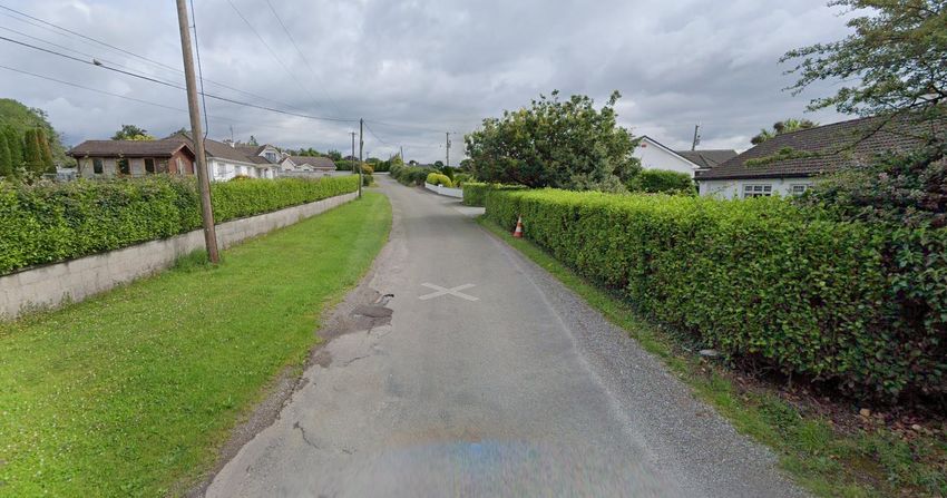
1. Introduction
1.1 Project Overview
The Celtic Interconnector is a subsea link that will enable the exchange of electricity
between the electrical transmission grids in Ireland and France.
The transmission grids in both Ireland and France are operated at High Voltage Alternating
Current (HVAC). High Voltage Direct Current (HVDC) is used for the transmission of
electricity over large distances where HVAC is not technically or economically feasible.
The main elements of the planned Celtic Interconnector project in Ireland are:
A High Voltage Direct Current (HVDC) submarine cable of approximately 500 km in
length laid between Brittany in France, and East Cork in Ireland;
A landfall area at Claycastle Beach, Youghal, Co. Cork, where the HVDC submarine
circuit will come onshore;
A HVDC onshore underground cable (UGC) circuit between the landfall area and a
converter station compound, planned to be located at the Industrial Development
Agency (IDA) Ballyadam landholding, east of Carrigtohill; this will convert the
electricity from HVDC to HVAC and vice versa;
A HVAC UGC circuit between the converter station compound and the connection
point to the National Grid at the existing ESB Networks (ESBN) Knockraha substation.
This will require a new Cable Sealing End Compound to facilitate this connection;
A fibre optic link, with associated power supply, will also be laid along the route for
operational control, communication and telemetry purposes.
1.2 Project Development
The Celtic Interconnector project has been in development for some ten years; a significant
portion of this time involved investigating, and ultimately confirming, the feasibility of the
project. The Irish onshore elements of the project have been developed in accordance with
EirGrid’s six-step Framework for Grid Development, as summarised in Figure 1.1. The
Framework ensures that project development occurs in a consistent and structured manner,
with adequate and appropriate opportunities for public and stakeholder participation in
project decision-making.
Figure 0.1: EirGrid Six-Step Framework for Grid Development (Source: EirGrid)
5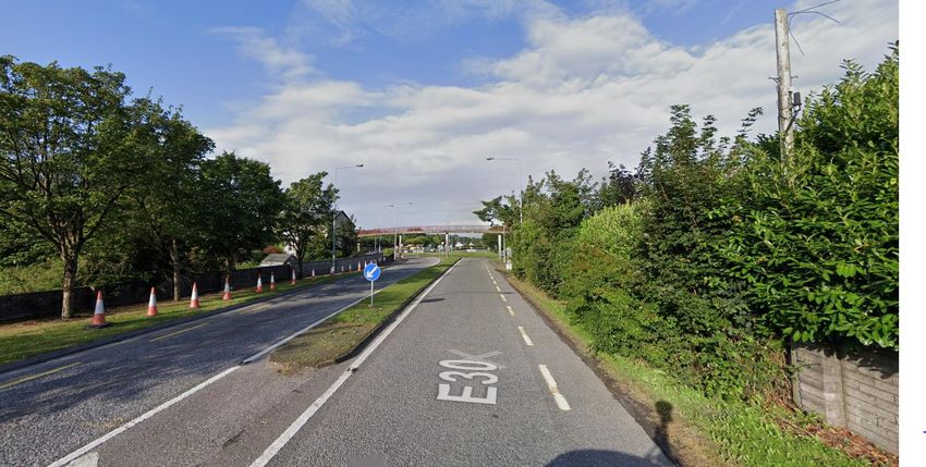
The Framework approach, in summary, is that each “Step” concludes with outcomes (such
as decisions, next steps etc.) that build upon each other. Deliverables within the Steps, such
as reports, brochures etc., are available on the project website at www.eirgridgroup.com.
With particular regard to the identification of siting and routing options for the Celtic
Interconnector project, EirGrid, together with its onshore Consultants Mott MacDonald, have
undertaken Steps 3 and 4 of the Framework, with associated deliverables including:
STEP 3: Onshore Constraints Report April 2019, identifying multiple options for
converter station sites and landfall locations. The report did not identify route options;
STEP 3: Preferred Options Report August 2019, identifying a shortlist of converter
station sites and landfall locations. Again the report does not identify route options,
however it confirms (Section 1.3 of the Step 3 report) that connections will be by way
of UGC, and that (Section 3.3.2 of the Step 3 report) it is EirGrid’s preference to install
the UGC within existing public roads;
STEP 4A: Consultant’s Development Options Report November 2019, identifying an
“Emerging Best Performing Option” (EBPO) for the project in Ireland, and for the first
time identifying project route options (Section 3 of the Step 4A report). While route
sections had been initially identified to inform consideration of the Step 3 site/landfall
options, these were considered in more detail in this report in respect of each
shortlisted converter station site and landfall location. Appendix C of the Step 4A report
identifies all the various route sections considered. Section 3.2.3 of the Step 4A report
specifically notes that various potential options had a common convergence in the
area of Churchtown, such that the report considered potential HVDC routes from the
Churchtown area to each Landfall Location, and HVDC routes from the Churchtown
area to each Converter Station Site;
STEP 4B: Consultant’s Development Options Report November 2020, identifying the
“Best Performing Option” (BPO) for the proposed onshore development in Ireland,
mapped at Appendix B of the Step 4B report, and reproduced at Figure 1.2 below. Of
note, the Step 4B report concludes (Section 5.1) that “this identified BPO is subject to
change as studies and assessments are ongoing ….. however, it will form the basis for
ongoing design and assessment up to presentation of a proposal for consenting…”.
The project is now in Step 5 of the Framework process, whereby the BPO forms the focus
for technical and environmental assessment (see Figure 1.2). This will culminate with
submission of applications for Statutory consent – in Ireland consents will be sought from the
Strategic Infrastructure Division (SID) of An Bord Pleanála (onshore element), and from the
Department of Housing, Local Government and Heritage (foreshore element).
6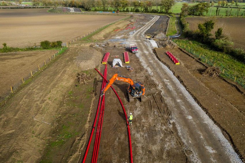
Figure 0.2: Map of Best Performing Option (BPO) for the Celtic Interconnector project, from Appendix B of the Step 4B
Consultant’s Development Options Report November 2020 (Source: Mott MacDonald)

1.3     Purpose and Scope of this Route Options Review

As noted above, in November 2020 EirGrid closed Step 4 with publication of the BPO. This
was communicated via two webinars, press advertising, a press release, an email to
registered email addresses (circa 600), a letter to registered stakeholders (circa 1500),
social media, and direct contact to elected representatives as well as to community
organisations who had engaged on the project. This was also covered by local and national
print and radio media.

Due to Covid restrictions, there was (and remains) a significant constraint to direct external
engagement activities (e.g. door to door calls). However, to ensure the message of the BPO
had been received by individuals and communities along the project route, EirGrid issued a
further letter in February 2021 to registered property owners on the project route, which
included direct contact details of the project Community Liaison Officers. This was issued by
EirGrid to the Property Registration Authority Ireland (PRAI) official sourced database of
landowners on the project route. (Circa 650).

EirGrid was subsequently contacted by a number of residents in the Churchtown /
Roxborough area (hereinafter referred to as “Churchtown”) with a number of stated
concerns, including that:-

                                                          7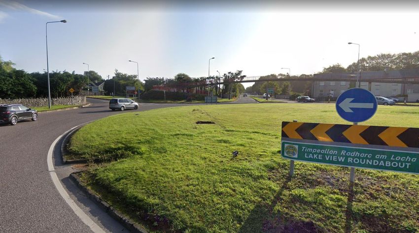
The project consultation process had excluded the Churchtown residents until now;
The residents of Churchtown had no knowledge of the project until now;
The laying of the HVDC UGC within the local road at Churchtown would have adverse
health impact from Electro-Magnetic Fields (EMF); and,
EirGrid should amend the BPO UGC route in the Churchtown area.
EirGrid subsequently had two online meetings with the Churchtown Residents Group (CRG)
in March 2021 to listen to, and respond to, concerns raised. EirGrid also met twice with the
East Cork Municipal District Council (MDC) in March 2021, where many of the CRG
concerns were also raised.
At these meetings, EirGrid committed to undertake a review of route options identified in the
Step 4A and Step 4B route identification processes. This review would also include
consideration of off-road/cross-country routes, which had not previously been considered
given EirGrid’s stated preference to install UGC within existing public roads as noted in
Section 1.2 above. This review was planned to be completed by the end of March 2021.
The Route Options Review concerns the area and environs of Churchtown. This comprises
a focused description of the various alternative route options in this area (see Figure 1.3),
and a comparative evaluation of same, identifying the considered Best Performing Option for
the HVDC UGC in the vicinity of Churchtown as of March 2021. While other queries were
raised during meetings with the Churchtown Residents Group relating to other potential
landfall areas etc., these are not included within this Review, as they are considered to have
been adequately considered through the project development process. Similarly, the choice
of technology is not being considered in this Review, for example the use of Overhead Line
(OHL), nor is the choice of converter station location or connection point (substation).
This Review has been undertaken by a team of Technical, Environmental, Ecological,
Planning, Engineering, Agricultural and other specialists in EirGrid, having regard to both the
issues raised by the CRG, and in engagement with representatives from key stakeholders
such as Cork County Council (CCC), Iarnród Eireann (IE), Transportation Infrastructure
Ireland (TII), and the Cork Roads Design Office (RDO).
8
There are therefore 5 main HVDC UGC alternatives that are considered in this Review –
these are mapped as indicative/illustrative options and outlined below. For comparative
purposes, all options are considered from the general intersection point of the planned off-
road HVDC UGC route at Castlemartyr with the Mogeely Road, to the site of the planned
converter station at the north-eastern portion of the IDA Ballyadam landholding – Table 1.1
below identifies the approximate distances of these options:-
The Shanty Path and Local Roads (Figure 1.3) – extending westwards on the N25
to the Two Mile Inn junction; a short off-road section in the vicinity of the junction of the
N25 at Two Mile Inn to avoid the existing junction; within the local road in Churchtown
(known as the Shanty Path); local road network to north of Midleton and south-
westwards to the converter station site;
The disused Midleton-Youghal railway corridor (Figures 1.4-1.9) - currently under
development by Cork County Council as a Greenway; access point options at Mogeely
and Ballinascartha; egress point options at the Shanty Path, Midleton – R627, and
extension along the existing Cork-Midleton railway line to the converter station site;
The existing N25 corridor (Figure 1.10) - extending west of N25 junction at Two Mile
Inn; to the south of Midleton to the area of the IDA Ballyadam site at Carrigtohill);
within the Ballyadam site; this portion of the N25 is currently planned for a major road
improvement;
The built-up area of Midleton (Figures 1.11-1.12) - extending west of N25 junction at
Two Mile Inn; access options from N25 via the R907 Youghal Road and the R630;
extending north to the local road network of the local road network;
Typical off-road/cross-country option in the vicinity of Churchtown (Figure 1.13)
– a study area has been identified for this option, as well as indicative/typical UGC
options extending on a south-east – north-west alignment (Option 1) and a south-north
alignment (Option 2); both options extend from the N25 to the off-road location of the
current BPO, west of the Shanty Path, south of the disused railway corridor.
9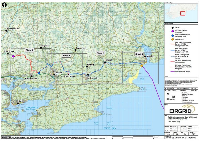
Figure 0.3: Map of Option along N25, Shanty Path and Local Roads (Source: EirGrid/ESRI)

Figure 0.4: Map of Option along Disused Railway Corridor from Castlemartyr to Shanty Path and Local Roads (Source:
EirGrid/ESRI)

                                                        10
Figure 0.5: Map of Option along Disused Railway Corridor from Castlemartyr to Midleton and Local Roads
(Source: EirGrid/ESRI)
Figure 0.6: Map of Option along Disused Railway Corridor from Castlemartyr to Ballyadam via existing operational
railway line corridor (Source: EirGrid/ESRI)
11Figure 0.7: Map of Option along Disused Railway Corridor from Ballinascartha to Shanty Path and Local Roads
(Source: EirGrid/ESRI)
Figure 0.8: Map of Option along Disused Railway Corridor from Ballinascartha to Midleton and Local Roads (Source:
EirGrid/ESRI)
12Figure 0.9: Map of Option along Disused Railway Corridor from Ballinascartha to Ballyadam via existing operational
railway line corridor (Source: EirGrid/ESRI)
Figure 0.10: Map of Option along N25 to Ballyadam (Source: EirGrid/ESRI)
13Figure 0.11: Map of Option along N25 via Midleton (R907) and Local Roads (Source: EirGrid/ESRI)
Figure 0.12: Map of Option along N25 via Midleton (R630) and Local Roads (Source: EirGrid/ESRI)
14Figure 0.13: Map of off-road study area, showing indicative alignments for off-road UGC options in the Churchtown
area (Source: EirGrid/ESRI)
Table 0.1: Approximate Distance (Km) of alternatives considered in this Route Options Review - calculated from off-
road HVDC at intersection with Mogeely Road, Castlemartyr to the Converter Station at IDA Ballyadam Landholding.
152. Approach and Methodology
2.1 Multi Criteria Analysis (MCA)
In accordance with EirGrid’s Framework for Grid Development, a comprehensive and
consistent multi criteria analysis has been applied to decision making over the various Steps
of project development, including in the consideration of a variety of alternatives. It is
appropriate that a similar approach is adopted in this Route Options Review in considering
alternative options for that portion of the HVDC UGC in the vicinity of Churchtown.
The multi criteria analysis considers the following criteria relating to project development, as
illustrated in Figure 2.1, as well as in relation to public and stakeholder feedback received:
● Technical;
● Economic
● Environmental
● Socio-Economic
● Deliverability
These align with EirGrid’s statutory obligations under Article 8 of the European Communities
(Internal Market in Electricity) Regulations, 2000 (SI 445/2000, which requires EirGrid as
State electricity Transmission System Operator (TSO) “to operate and ensure the
maintenance of and, if necessary, develop a safe, secure, reliable, economical and efficient
electricity transmission system, and to explore and develop opportunities for interconnection
of its system with other systems, in all cases with a view to ensuring that all reasonable
demands for electricity are met and having due regard for the environment”.
Figure 2.1: EirGrid’s Assessment Criteria (Source: EirGrid)
162.2 The Performance Matrix
The MCA approach facilitates a balanced consideration of the technical, economic,
environmental, socio-economic and deliverability aspects of a development project.
The overall evaluation in MCA is based on expert judgement; this is informed by various
tools such as publically available datasets and established guidelines or other documents,
as well as feedback received from public and stakeholder engagement. In this instance, the
MCA also has had regard to assessment and analysis undertaken to date in respect of the
Celtic Interconnector project, as captured in the various reports available on the project
website at www.eirgridgroup.com.
The key decision-making tool in the MCA approach is the performance matrix (Figure 2.2).
This is a qualitative tool which uses the standard set of criteria to assess all options by
means of colour coding. Evidence substantiating the colour coded matrix is also
documented. This ensures visibility and transparency in the evaluation process.
Figure 2.2: Typical Performance Matrix and identified criteria (qualitative scoring of options indicative only and do not
relate to this Route Options Review)
173. Relevant Matters of Construction and Operation
3.1 The Appointed Contractor
The Celtic Interconnector, including the HVDC UGC between the landfall area at Claycastle
Beach and the converter station at Ballyadam, is being planned by EirGrid together with its
specialist technical and environmental consultants. However, the actual construction of the
project will be undertaken by an appointed Contractor.
Consents for the proposed development are usually accompanied by stipulated conditions
set out by the decision-making authority. In the case of the DC UGC, the decision-maker is
the Strategic Infrastructure Division (SID) of An Bord Pleanála. These conditions require
significant matters of detail to be agreed post-consent between the developer and the
planning authority – in this case Cork County Council (CCC). CCC will ultimately be
responsible for ensuring all conditions are discharged and complied with.
As part of this post-consent process, the Contractor will carry out detailed surveys and other
site investigations, and ultimately draw up a detailed design of the consented development –
exactly where the cable will be laid (within the area of the consented development) , and any
other specific matters for its construction and installation.
The contractor will also prepare a detailed Construction Environmental Management Plan
(CEMP), Traffic Management Plan (TMP), Waste Management Plan (WMP), and other
Management Plans and/or associated Method Statements. In particular:-
The CEMP is a ‘live’ document which is reviewed regularly and revised as necessary
to ensure that the measures being implemented are effective. The primary objective of
the CEMP is to safeguard the environment, site personnel and nearby sensitive
receptors – including people and properties - from site activity which may cause harm
or nuisance. The CEMP sets out a project framework to ensure key mitigation
measures and conditions of the consent process are translated into measurable
actions, and are appropriately implemented during the construction phase of the
development. As part of this framework, EirGrid will oversee the Contractor’s delivery
of transparent and effective monitoring of the receiving environment during
construction to inform and manage on-going activities on site and to demonstrate
effectiveness of the measures outlined therein.
The TMP will be developed and implemented to mitigate any potential construction
traffic impacts on the public road network. All construction activities, including
construction traffic, will be managed through the CEMP.
When agreed with the planning authority, these Management Plans and Method Statements
are also approved by a Clerk of Works (CoW) and Environmental Clerk of Works (EnCoW)
prior to commencement of any works. The EnCoW is responsible for ensuring that all
environmental and ecological mitigation measures detailed in the contractor’s CEMP and
any associated Method Statements, are implemented in full, as well as on-site monitoring
18and reporting. The EnCoW may be supported by further technical specialists, to monitor, and
oversee protection (e.g. for ecology, archaeology or water quality).
Overseen by EirGrid, the Contractor will also make all monitoring reports available to the
planning authority and other statutory bodies as required.
The Contractor will also have responsibility for ongoing liaison with communities and
landowners regarding matters of construction of the project. However, EirGrid’s Community
Liaison Officers (CLOs) and Agricultural Liaison Officers (ALOs) will also continue to actively
participate on the project, and be available to landowners, residents and communities.
3.2 Cable Route Installation Schedule
The laying of underground cables is a standard construction technique undertaken by a
range of utility and other services providers. Cables will typically be installed in two phases,
as follows:
● Duct and joint bay installation; and
● Cable pulling and jointing
Duct and joint bay installation (see Section 3.3 below) are the most construction-intensive
and invasive elements of cable route installation, as digging of a trench will be required. For
on-road cable laying, this phase will have the largest impact on traffic disturbance, including
the potential need for rolling road closures (to through traffic) and diversions. While the
specifics of any cable laying schedule are dependent upon the nature and location of the
project, it is generally the case that cable ducts can be laid in a road at a rate of
approximately 50m plus per day. Joint bays, generally located at intervals of 750 metres
along the HVDC route of the Celtic Interconnector (shorter intervals occur where the route
alignment is more complex), are typically installed in 1 – 2 days with the road fully reinstated.
Road reinstatement along the route of the cable trench follows the completion of the
trenching and ducting as it moves along the route. Cable pulling and jointing, which
commence when the trenching and ducting is well advanced along the route, is executed
from the joint bay locations. Where this activity would likely require a road closure to be
undertaken, the provision of a passing bay at the location of the joint bay will facilitate
through movement of traffic along the road by means of a single traffic signalled lane at the
joint bay.
3.3 Underground Cable Construction
The following sections describe the key project elements of the DC UGC route. It should be
noted that this construction methodology is the same as for any Alternating Current (AC)
UGC route – for example as proposed for the Celtic Interconnector between the converter
station at Ballyadam and the grid connection point at Knockraha, Co. Cork, or as undertaken
on other cable-laying projects in Ireland.
19Underground Cable Laying in Public Roads
The UGC will be pulled into pre-installed ducts laid within a trench. The installation
conditions of the cable, including depth, affect its performance. The standard trench
dimensions for a DC UGC is approximately 0.8m wide x 1.3m deep. The final specific trench
dimensions will be confirmed by the appointed DC UGC contractor at detailed design stage.
Traffic control measures will be implemented as appropriate, including road diversions,
closures and stop / go traffic management. Once the traffic control measures are in place,
the road surface will be saw-cut to the width of the trench and excavated to the required
depth, generally using an excavator with hydraulic breaker. Where underground services are
present, excavation around these services may require to be by hand digging. The trench
walls are temporarily supported, typically with wooden shuttering boards. When a trench
length of approximately 20m to 50m has been excavated and temporarily supported, a layer
of bedding material (sand, concrete or sand / cement mix) is laid onto the base of the trench.
The ducts are then installed onto the bedding in the correct arrangement, and the trench is
backfilled and compacted with thermally suitable back-fill material and marker boards for
protection. Following duct installation, the road above the trench will be reinstated to match
the environment in which it is installed to the standard required by the relevant authority at
that location, in this case Cork County Council (CCC).
The duct installation will progress sequentially starting at one joint bay and moving towards
the next joint bay along the route. The construction area moves along in tandem with the
progress of the duct installation, with only the relevant portion of the section cordoned off
while under construction.
Figure 3.1 shows a typical trench in a public road for a pair of HVDC cables after installation
of ducts and prior to back fill. Marker boards can be seen within the trench prior to road
reinstatement.
Figure 3.1: Typical DC trench laid in the public road (source EirGrid)
20For trench excavation works in roads where space is relatively unconstrained, an excavator
is typically used to load a truck with excavated material. The truck extracts the material away
from site for appropriate remediation or storage. For roads with a width greater than 3m, an
average rate of construction for the cable route is approximately 50m per day. In places, it
may be slower than this, particularly where utilities are present and digging by hand may be
required; however, across the period of construction, 50m a day is considered a
representative average for the proposed works.
Joint Bays and Passing Bays
Cable is manufactured and delivered to site on drums, in lengths of approximately 750
metres. This requires the installation of joint bays along the cable route to connect
consecutive lengths of cable together and to facilitate cable pulling.
Joint bays are underground chambers which are used to pull the various lengths of UGC
through the pre-installed ducts, and to connect (“joint”) together those lengths of UGC into a
single overall circuit. A HVDC UGC joint bay is typically 8m x 2.5m x 2m (Figure 3.2).
Provision will also be made for the installation of communications chambers and link box
chambers at joint bay locations. The communications chambers are used to join a fibre optic
communications cable, while the link box chambers are used to accommodate the link box,
which earths the outer sheaths of the power cables. The chambers are provided with
removable lids and access to the chambers will be required on a permanent basis to
facilitate maintenance. Typically, these chambers are located within the verge to minimise
traffic disruption during routine maintenance; this would be similar to other fibre optic or
telephone cables.
The open concrete chamber will temporarily support the retained ground on the outside of
the chamber during the ducting activities. Once these activities are completed, the open
chamber will be temporarily backfilled with appropriate material and the road temporarily
reinstated to the satisfaction of the planning authority until such time as cable installation
occurs (see further below).
21Figure 3.2: Typical Joint Bay under construction.
Joint bays are not readily accessible during operation, as there is no ongoing maintenance
required; however, they need to be immediately accessible in the unlikely event of cable
failure requiring cable replacement. The extent to which traffic management or other
measures would be required in this situation will depend on the location of the joint bay
within the roadway.
During the construction phase of the project, where a joint bay is located in a road of a width
requiring its closure to undertake the cable pulling and jointing, the provision of a passing
bay at the location of the joint bay will facilitate the through movement of traffic along the
road by means of single traffic signalled lane at the joint bay. Where a passing bay is not
provided in these circumstances, a road closure is required to undertake the work.
The installation of the passing bay entails the removal of the top layer of ground to the side
of the carriageway and temporarily storing it locally to the side for reinstatement following the
works. The passing bay will then be constructed to a standard agreeable to the planning
authority.
This passing bay can then be used for diverted traffic whilst the joint bay works are
conducted. Figures 3.3 and 3.4 show passing bays that have been developed for other cable
projects.
22Figure 3.3: Photograph of Passing Bay under construction (Source: EirGrid)
Figure 3.4: Photograph of Passing Bay in operation. The steel structure in the middle of the picture behind the Harris
fence has been placed on top of the joint bay to form an enclosed workspace where cable jointing is taking place.
(Source: EirGrid)
23In identifying locations for joint bays and associated passing bays along the route, EirGrid
will always take care to minimise the amount of mature trees that are required to be
removed, having regard for third party landowners, ecological, and landscape impact.
Overseen by EirGrid, the Contractor will carry out suitable reinstatement of all vegetated
areas, having regard for sensitive ecological features, and opportunities for biodiversity
enhancement of road verges, and hedgerows, relative to pre-construction.
Cable Installation and Jointing
As noted above, the cables will be brought to site on cable drums. Once the drum is set up,
a winch system including pulling cable will be attached to the nose of the cable and rollers
will be used to guide the cable end towards the duct (Figure 3.5).
Figure 3.5: Photograph of cable installation into the pre-laid ducts at a joint bay (Source: EirGrid)
The cable jointing process is technically complex, and essential to the effective operation of
the cables. For this reason, a temporary waterproof shelter system is either placed or
constructed around the joint chamber, to protect the cable from moisture and to provide a
clean environment in which the jointing process can be undertaken (see Figure 3.6).
Within the joint bay, the cables are pulled into each end of the chamber. The cable ends
jointed together within the chamber. Jointing is expected to take approximately one to two
weeks per joint bay. It should be noted that jointing usually occurs some significant period of
time following cable pulling, and is carried out by specialist personnel.
24Following jointing, the joint bay will be backfilled and the road surface permanently reinstated
to the standard required by the planning authority at that location.
Figure 3.6: Typical HVDC Cable Jointing Bay enclosure (Source: EirGrid)
Underground Cable Laying in Agricultural Lands
Underground cables laid within agricultural lands (grassland and tillage land) require the
same essential components, and follow the same construction methodology as for cable
laying in public roads – including trenching and ducting, provision of joint bays, and cable
installation and jointing.
EirGrid typically does not acquire these lands but undertakes the works on the basis of a
wayleave or easement. This approach provides the necessary rights to lay the cable and
provisions for the reinstatement of land. The works on the lands will be undertaken in
accordance with a project specific Code of Practice. This provides for a best practice
approach to soil management during the works. This approach is a driver for the changes to
the construction methodology when compared to that for laying cables in the road
For off-road or cross-country sections of the Celtic interconnector, a temporary working strip
of minimum 30m in width is proposed. While the cable trench is typically 1m in width, the
30m working strip is required for the following reasons;
25 To facilitate the storage of topsoil which must be removed from;
o The footprint of the temporary construction access track (typically up to 5m in
width)
o The footprint of the cable trench
o A buffer strip between the temporary access track and the trench (for safety)
o Subsoil storage area
o Materials storage areas
To facilitate the laying of the temporary construction access track alongside the cable
trench to allow for the movement of construction equipment and materials along the
section of the route on the farmland.
To facilitate the excavation of the cable trench and the installation of the cable ducting.
To facilitate the storage of distinct layers of subsoils excavated from the cable trench in
segregated piles for later reinstatement to the original soil profile.
Figure 3.7 shows a typical temporary working strip on agricultural land for electricity cable
installation. Stripped topsoil can be seen stored to the left of the strip, temporary construction
access road in the centre right with subsoil stripped areas either side for trench installation,
materials storage and sub-soil storage.
As noted above, where cables are placed in a public road, the road itself serves to facilitate
the movement of vehicles, and the material excavated from the trench is removed off site
and so no soil storage areas are required. Similarly, when trenching, ducting and joint bay
installation has been completed on a given section of public road, the road can be reinstated
for full public use. Cable pulling and jointing works, which as also noted above may not occur
for some period (often many months) afterwards at the joint bays, are serviced with materials
and equipment by the public road itself.
However, on agricultural land, the temporary access road must remain in place until cable
pulling and jointing works have been completed, as it is required to facilitate the movement
of materials, equipment and personnel to and from the joint bay locations sited on the land.
For this reason, it is anticipated for the Celtic Interconnector project that any off-road working
strip will be unavailable to an affected landowner for a period of up to 18 months - from initial
fencing-off to removal of the fence following establishment of grass on the reinstated strip.
Usually, a cross-country cable alignment seeks to follow field boundaries so as to minimise
impact on farm operations. There will however be a requirement to cross a number of fields,
ditches, hedgerows, or other features as necessary. For minor watercourses, where
Horizontal Directional Drilling (HDD) is not employed, watercourse crossings employs an
open trench method, which requires removal of field boundaries in the area of the cable
alignment, with associated culverting of drainage ditches etc. Such works are normally
carried out ‘in the dry’, employing suitable methods to avoid significant impacts to fisheries,
in consultation with Inland Fisheries Ireland. When crossing larger watercourses, HDD is
generally employed underneath the watercourses, avoiding the need for instream works.
Use of HDD methods does, however, require temporary use of an off-road area of land at
26either side of the crossing (c. 50 x 60m), to establish reception and launch pits for the cable,
and to facilitate other works and storage etc.
In accordance with Best Practice Guidance (CIRIA Environmental good practice on site
guide (4th edition) 2015), a minimum set back distance of 10 metres will be maintained
between the works area and any streams (other than where these require to be culverted), in
order to ensure the environmental protection of those waterbodies. The demarcation of the
works area with construction fencing will ensure that no works will occur outside this area.
Overseen by EirGrid, the Contractors’ Environmental Clerk of Works, will design and
implement watercourse and other ecological protection measures as appropriateto the
conditions at each working location. The Contractor would agree such measures as part of
the CEMP, to be agreed with Cork County Council and (where additionally required), other
stakeholders including Inland Fisheries Ireland, and the National Parks and Wildlife Service.
In addition to complying with planning conditions, the Contractor will be required to obtain
and comply with any relevant licences associated with works impacting bridges,
watercourses, or ecological features.
Figure 3.7: Typical UGC construction in agricultural lands (Source: EirGrid)
Reinstated agricultural areas will be seeded as agreed with a landowner.
273.4 Other Matters
Operation and Maintenance
On completion of works on agricultural land a permanent easement measuring 14m in width
is required. This is centred on the cable trench and extends for the full length of the cable on
the off road section.
The easement serves to ensure the safety and security of the cable and to facilitate access
to the cable and any repair or maintenance that may be required in the future by restricting
land uses (e.g. development and tree planting) within this area. Normal farm cropping
practices can resume on the easement strip on completion of the work and reinstatement of
the land.
Cable Laying and Trees
The presence of trees on or in immediate proximity to cable routes requires careful
consideration and management. During periods of low or no rainfall, increased drying of the
soil due to root capillary action may affect the thermal capability of the cable system. Tree
root systems may also get entwined around the cables causing damage to the ducts and
cables. As a result, it is generally the case that sufficient distance is required to occur
between a cable alignment and trees.
For narrow roads, the cable alignment may need to be installed in the centre of a
carriageway, or may need to switch from one side of the road to another to reduce the
impact on trees and also to accommodate the trench excavation works. This is a matter that
is confirmed at the post-consent detailed design of a cable project.
If cables have to be laid in close proximity to trees, and in particular to large / mature trees,
excavation by hand may need to be employed in order to ensure protection of root systems.
Hand excavation is typically slower than mechanical excavation techniques.
284. EMF and DC Underground Cables
4.1 Introduction
This section has been prepared with regard to expertise within and available to EirGrid, and
with reference to a number of relevant documents including:-
EirGrid: The Electricity Grid and Your Health – available at
https://www.eirgridgroup.com/site-files/library/EirGrid/EirGrid-The-Electricity-Grid-and-
Your-Health.pdf
EirGrid: Electric and Magnetic Fields (EMF) Facts and the East West Interconnector –
available at https://www.eirgridgroup.com/site-
files/library/EirGrid/EMF%20Factsheet.pdf
EirGrid: Evidence Based Environmental Studies – Study 1 EMF – available at
https://www.eirgridgroup.com/site-files/library/EirGrid/EirGrid-Evidence-Based-
Environmental-Study-1-EMF.pdf
ESB: EMF and You - Information about Electric & Magnetic Fields and the electricity
network in Ireland - available at https://esb.ie/docs/default-source/default-document-
library/emf-public-information_booklet_v9.pdf?sfvrsn=0
Tennet: Living near HighVoltage Installations Electrical and magnetic fields – available
at
https://www.tennet.eu/fileadmin/user_upload/Company/Publications/Corporate_Brochu
res/Living_near_High-Voltage_Installations.pdf
Ecofys: Study on the Comparative Merits of Overhead Electricity Transmission Lines
Versus Underground Cables prepared for the Department of Communications, Energy
and Natural Resources Ireland – available at
http://www.soni.ltd.uk/media/documents/Projects/Publications/6-ECOFYS-Study-Final-
report-June2008.pdf
The website of the International Commission on Non-Ionizing Radiation Protection
(ICNIRP) and various guidelines – at www.icnirp.org
Electric and magnetic fields, often referred to as EMFs, are produced both naturally and as a
result of human activity. Natural sources of EMFs include the earth’s geomagnetic field and
electric fields from storm clouds. When electric current flows, both electric and magnetic
fields are produced and therefore are present wherever electricity is used, such as in the
home, office or farm (see Figure 4.1), and in the vicinity of equipment that makes up the
electricity supply system.
29A “field” is defined by the force it exerts on an object placed in it; for example, a gravitational
field is used to describe the force of attraction that the Earth exerts on living beings and
objects situated within its influence.
Electric and magnetic fields can be considered as the regions around electrical equipment in
which these effects can be felt or measured. Electric fields are produced by voltages,
irrespective of how much current is flowing and indeed whether any current is flowing at all.
Magnetic fields are produced by currents, irrespective of the voltage.
EMFs can be harmful at very high levels - levels much greater than those to which we are
normally exposed. For this reason, independent and authoritative international panels of
scientific experts have reviewed studies on possible health effects from EMFs for decades.
These have consistently concluded, based on the weight of evidence available, that the
power frequency electric and magnetic fields encountered when electrical equipment is
properly designed and constructed do not cause adverse health effects in humans in normal
living and working conditions.
As noted in Figure 4.1, the EMF emitted by HVDC transmission infrastructure is at an
extremely low frequency which is at the non-ionising end of the electromagnetic spectrum.
EirGrid designs, develops and operates the transmission grid in accordance with stringent
safety recommendations which are made by national and international agencies. Several of
these recommendations come from the International Commission for Non-Ionizing Radiation
Protection (ICNIRP). This is an independent body, funded by public health authorities around
the world. ICNIRP has investigated the safety of EMFs, and provides guidance on safe
levels of exposure. This is addressed in more detail further in this section.
30Figure 4.1: EMFs from different sources (source: EirGrid)
314.2 EMF and Underground Cables
It is a fact that electricity cables have been placed underground in Ireland since the 1960’s.
There are currently approximately 320 km of underground transmission cabling in Ireland,
with multiples of this figure of underground cabling associated with the lower-voltage
distribution system. In addition, new underground cabling projects are being completed or
planned on an ongoing basis both by EirGrid as developer of the electricity transmission
system, and by ESB Networks (ESBN) as developer of the electricity distribution system.
This figure does not include the High Voltage Direct Current (HVDC) underground cable
(UGC) of EirGrid’s East West Interconnector (EWIC) which is approximately 44.5 km in
length on land in Ireland, and is laid primarily in public roads between the interconnector
landfall at Rush North Beach, through the main street of Rush, Co. Dublin, and the EWIC
converter station at Woodland, near Batterstown, Co. Meath.
The Celtic Interconnector HVDC UGC will use cross-linked polyethylene (XLPE) insulated
cables with a grounded metallic sheath. The typical construction of such a cable is shown in
Figure 4.2.
Figure 4.2: Typical XLPE Cable Construction (Source: Nexans)
The inner ‘core’ of the cable will be constructed of copper or aluminium wires. This ‘core’ is
referred to as the conductor and will carry the electrical currents that will transfer power
along the interconnector. The conductor is surrounded by an insulating XLPE jacket, which
will be of sufficient electrical strength to withstand the voltage applied to the conductor. The
insulation is then enclosed within a continuous metallic sheath, which acts as a water barrier
and ensures that the insulation is exposed to a uniform electrical field.
32The metallic sheath is grounded (connected to the mass of earth) at joint bay locations along
the length of the cable. This has the effect of ensuring that the electric field is entirely
contained within the structure of the cable. As the metallic sheath is connected to ground,
there can be no significant electric field between it and any other object connected to
ground. For this reason, cables with a continuous metallic sheath cannot generate external
electric fields, provided that the metallic sheath is grounded. Consequently, electric field
exposure does not need to be considered as a potential impact of the cable installation.
The cable will generate static magnetic fields, which will not be screened by the metallic
sheath. The current in HVDC cables, being equal and opposite in direction, results in a very
low magnetic field
4.3 EMF Policy and Guidance
In Ireland the following bodies are responsible for policy and guidance relating to EMF;
The Department of Environment, Climate and Communications is responsible for
national policy, including that relating to the health effects of non-ionising radiation,
including EMF;
The Environmental Protection Agency (EPA) is responsible for the provision of advice
and guidance in relation to public exposure to EMF. In May 2019, Regulation S.I. 190
of 2019 was signed into law to extend the functions of the EPA to cover public
exposure to EMF. These functions include: (a) to provide advice to the Government
and the public on exposure to EMF (including on relevant standards for public
protection); (b) to monitor scientific/technological developments likely to impact on
public exposure to EMF; and (c) to carry out independent monitoring of public
exposure to EMF to support its advisory role;
The Health & Safety Authority (HSA) regulates exposure to EMF in the workplace. The
regulations, set out in SI No 337 of 2016, require employers to carry out a risk
assessment on EMF exposure in workplaces.
All of these bodies reference the ICNIRP international guidelines, which are endorsed by the
World Health Organisation (WHO) and the European Union (EU).
For static magnetic fields, the 2009 ICNIRP guidelines define a recommend general public
exposure limit in terms of a measured magnetic field of 400,000 microtesla. However, it is
noted that exposures in excess of 500 microtesla may affect cardiac pacemakers or other
implanted devices. It is EirGrid’s policy, in accordance with National policy, to design and
operate the electricity transmission system such that these limits are not exceeded.
334.4 EMF and the Celtic Interconnector
The effects of EMF diminish rapidly with increasing distance from the source. The potential
of the Celtic Interconnector to contribute to public exposure to EMFs has therefore been
assessed at a number of worst-case locations including immediately above the centre line of
the DC cable circuit.
In accordance with EU recommendations, public exposure to EMFs is assessed at a height
of 1m above ground. This represents the likely effect of the fields on the central nervous
core of the body. As noted above, the HVDC cable will generate static magnetic fields, which
will not be screened by the metallic sheath. However, the effects of these fields at 1m above
ground level can be accurately predicted.
The static magnetic field directly over the UGC, when the cable is at maximum circuit
loading, is predicted to be comparable with the naturally occurring earth’s magnetic field.
This is multiples lower than the exposure limits which the ICNIRP guidelines recommend for
magnetic fields as set out above (400,000 microtesla).
Based on the calculations of the magnetic flux density and the design of the cable
infrastructure, there will be no impact on residential properties from the HVDC UGC
alignment as the ICNIRP guidelines are not exceeded. The HVDC Cable route therefore is
assessed as having no significant adverse effects arising from EMF.
4.5 EMF and the Precautionary Principle
It is noted that the conclusions set out in Section 4.4 are based on scientific calculation and
certainty rather than expert judgement and opinion. In such a context, it is considered that
the precautionary principle does not apply. As noted in the Ecofys Study on the Comparative
Merits of Overhead Electricity Transmission Lines Versus Underground Cables:-
“The precautionary principle is exercised where scientific information is deemed to be
insufficient, inconclusive or uncertain, and where there are indications that potential
negative impacts on the environment, or human, animal or plant health may [be]
dangerous and inconsistent with the standard level of protection.” (P.143).
It is clear that in this instance, the scientific information is sufficient, conclusive and certain
that the maximum magnetic field generated from the HVDC UGC will be comparable with the
naturally occurring earth’s magnetic field. The calculated level will be many multiples below
the ICNIRP guidance limit of 400,000 microtesla.
Given the above, there is no requirement for any precautionary principle to be employed.
There will be no impact to people within residential properties at any distance from the
HVDC UGC alignment, nor indeed to anyone standing on the road directly over the UGC.
The HVDC UGC therefore is calculated as having no adverse effects arising from EMF.
34You can also read