Dynamic Friction and Wear in a Planar-Contact Encapsulated Microball Bearing Using an Integrated Microturbine
←
→
Page content transcription
If your browser does not render page correctly, please read the page content below
JOURNAL OF MICROELECTROMECHANICAL SYSTEMS, VOL. 18, NO. 2, APRIL 2009                                                                                        263

         Dynamic Friction and Wear in a Planar-Contact
            Encapsulated Microball Bearing Using
                 an Integrated Microturbine
         Matthew McCarthy, Member, ASME, C. Mike Waits, Member, IEEE, and Reza Ghodssi, Member, IEEE

   Abstract—The demonstration and characterization of a novel                                 for actuation and power generation. Efficient power trans-
planar-contact encapsulated microball bearing using a radial in-                              mission devices like motors and generators need small gaps
flow microturbine are presented. Stable operation of the air-                                 manufactured uniformly over relatively large areas, suggesting
driven silicon microturbine is shown for over 1 000 000 revolutions
at speeds, pressure drops, and flow rates of up to 10 000 r/min,                              the need for MEMS fabrication techniques. The achievement of
0.45 lbf/in2 , and 3.5 slm, respectively. Incorporation of a gas                              millimeter-scale bearings capable of defining micrometer-scale
thrust plenum using a novel packaging scheme has enabled                                      gaps is a necessity for microactuators and powerMEMS de-
comprehensive spin-down friction characterization of the encap-                               vices. Silicon-based MEMS bearings are desirable over meso-
sulated microball bearing. An empirical power-law model for                                   scale bearings made using traditional fabrication processes due
dynamic friction has been developed for speeds of 250–5000 r/min
and loads of 10–50 mN, corresponding to torques of 0.0625–                                    to their ability to be scaled down and integrated with electrical
2.5 µN · m and friction torque constants of 2.25–5.25 ×                                       and mechanical elements. Micromachines capable of delivering
10−4 µN · m/r/min. The onset and effect of wear and wear debris                               1–100 mW are envisioned for actuator applications at speeds
have been studied, showing negligible wear in the load bearing                                ranging from 10 to 100 000 r/min. Low-speed rotary positioners
surfaces for the operating conditions considered.      [2008-0109]                            for directional sensor systems would only need to overcome
  Index Terms—Microballs, microelectromechanical systems                                      bearing friction and operate around 10–100 r/min, while electri-
(MEMS) bearings, microturbines, rolling friction, spin-down.                                  cally actuated micropumps will require at least 10–100 mW of
                                                                                              delivered power at 10 000–100 000 r/min for efficient pumping.
                             I. I NTRODUCTION                                                 High-performance magnetic microgenerators are aimed at pro-
                                                                                              ducing watt-level power at speeds in excess of 100 000 r/min.

B     EARINGS are crucial components in modern machinery,
      playing a critical role in performance and reliability. They
provide a support mechanism for moving parts, greatly reduc-
                                                                                              In all cases, the power dissipated through bearing friction will
                                                                                              ideally count for a small fraction of the overall power, and low-
                                                                                              wear operation is a necessity for long life.
ing friction and wear, and have allowed the realization of a                                     While the development of MEMS-fabricated bearings is
wide variety of technologically advanced rotary machines like                                 still in its infancy, several different support mechanisms have
motors, generators, pumps, compressors, and turbines. Accord-                                 been demonstrated for use in micromachines. These include
ingly, the development of these machines at the micro- and                                    both direct-contact bearings, like flange and center-pin designs
millimeter scales requires a reliable support mechanism that can                              [1]–[7], and noncontact bearings, like electrostatic levitation
be easily fabricated and integrated with various components.                                  [8], magnetic levitation [9], and gas lubrication [10]–[13]. The
Microelectromechanical systems (MEMS) fabrication allows                                      first MEMS-fabricated motors used direct-contact bearings
for the immediate integration of electric and magnetic elements                               and were made from surface micromachined polysilicon.
                                                                                              Fan et al. [1] and Tai et al. [2] demonstrated side-drive variable
                                                                                              capacitance micromotors, with diameters of 60–120 µm,
   Manuscript received April 28, 2008; revised November 21, 2008. First
                                                                                              using both flange and center-pin bearings. It was concluded
published February 24, 2009; current version published April 1, 2009. This                    that friction played a dominant role in dynamic performance,
work was supported by the U.S. Army Research Laboratory under Grant                           limiting the devices to speeds of 500 r/min. Mehregany et al. [3]
CA#W911NF-05-2-0026. Subject Editor L. Lin.
   M. McCarthy was with the MEMS Sensors and Actuators Laboratory,
                                                                                              have demonstrated harmonic and salient-pole side-drive micro-
Department of Electrical and Computer Engineering, Institute for Systems                      motors supported on direct-contact bearings for speeds of up to
Research, University of Maryland, College Park, MD 20742 USA. He is now                       25 000 r/min, with particular emphasis on investigating friction
with the Department of Mechanical Engineering, Massachusetts Institute of
Technology, Cambridge, MA 02139 USA (e-mail: mattmcc@umd.edu).
                                                                                              and wear [4], [5]. By monitoring variations in the motor gear
   C. M. Waits is with the U.S. Army Research Laboratory, Adelphi, MD                         ratio, tribological characteristics of the direct-contact bearings
20783-1197 USA (e-mail: cwaits@arl.army.mil).                                                 were extracted. Significant wear was observed, leading to
   R. Ghodssi is with the MEMS Sensors and Actuators Laboratory,
Department of Electrical and Computer Engineering, Institute for Systems                      variations in motor performance over time and limiting overall
Research, University of Maryland, College Park, MD 20742 USA (e-mail:                         life. By using these devices and testing procedures, Dhuler et al.
ghodssi@umd.edu).                                                                             [6] showed coefficients of friction for the bearing surfaces from
   Color versions of one or more of the figures in this paper are available online
at http://ieeexplore.ieee.org.                                                                0.38 to 0.55, for a variety of dry gas environments. In addition,
   Digital Object Identifier 10.1109/JMEMS.2009.2013407                                       Beerschwinger et al. [7] have investigated the frictional

                                                                        1057-7157/$25.00 © 2009 IEEE

                Authorized licensed use limited to: IEEE Xplore. Downloaded on April 13, 2009 at 13:01 from IEEE Xplore. Restrictions apply.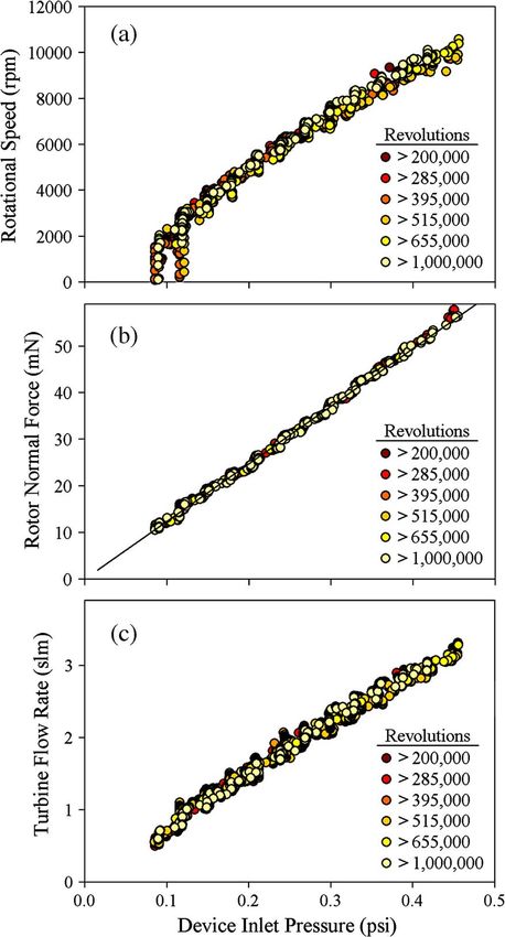
264                                                                                    JOURNAL OF MICROELECTROMECHANICAL SYSTEMS, VOL. 18, NO. 2, APRIL 2009

characteristics of polysilicon microbearings on various
substrate materials, finding similar values for coefficient of
friction.
   The most relevant demonstration of a noncontact MEMS
bearing is the gas-lubrication system developed for the MIT
Microengine Project [10]–[14]. By using hydrostatic thrust and
journal bearings, Livermore et al. [12] have achieved angular
speeds and torques of 55 000 r/min and 3.5 µN · m, respec-
tively, in a 4.2-mm-diameter electric induction micromotor.
Fréchette et al. [14] have demonstrated 4.2-mm-diameter
microturbines supported on fluid film bearings at angular and
tip speeds of up to 1.4 × 10⁶ r/min and 300 m/s, respec-
tively, showing the feasibility of these systems for high-power-
density turbomachinery applications. Gas-lubricated bearings
show a considerable reduction in friction and wear compared
to contact-type bearings and have accordingly been used to
achieve substantially higher speeds. These systems, however,
suffer from fabrication complexity, rotor instability, and the
necessity of advanced control schemes. Continued work is
required to better understand the stability characteristics of
microgas bearings and allow their implementation into practical
applications.
   With inherent tribological and system-level benefits, mi-
croball bearings represent a compromise between the more ex-
tensively studied gas-lubricated and contact bearings. Microball
bearings provide a simple, stable, and robust support mecha-
                                                                                            Fig. 1. Microturbine device showing (a) the microball-bearing geometry
nism for PowerMEMS devices. While gas-lubricated systems                                    (∅ = 285 µm), (b) the blade design and flow direction, and optical pho-
have superior speed and friction characteristics, microball-                                tographs of (c) the device cross section with a 10-mm diameter rotor, (d) top
bearing-support mechanisms are notably simpler to fabricate                                 side with fluid ports and speed bump structures, and (e) the bottom-side thrust
                                                                                            surface. Total device dimensions are 23 mm × 23 mm × 1.5 mm.
and operate. Similarly, microball bearings provide increased
tribological performance over sliding contact bearings [15],                                decoupled in this paper, allowing for comprehensive spin-down
[16], where friction and wear substantially impact the operation                            friction testing under a variety of operating conditions relevant
and life of such devices.                                                                   to next-generation microball-bearing-supported PowerMEMS
   In the linear and rotary ball-bearing-supported variable-                                devices.
capacitance micromotors reported by Ghalichechian et al.
[17]–[19], a silicon slider (or rotor) sits on top of steel micro-
                                                                                                                  II. M ICROTRIBOLOGY D EVICE
balls housed in rectangular trenches and is actuated via in-
plane electrostatic forces. Friction increases with speed until                                A radial in-flow microturbine packaged together with a
the motors cannot generate enough force/torque to maintain                                  bottom-side thrust plenum has been developed to investigate
synchronization with the moving element, corresponding to                                   the dependence of speed and normal load on dynamic friction
maximum linear and rotary speeds of 7 mm/s and 500 r/min,                                   and wear in a planar-contact encapsulated microball bearing.
respectively. Similarly, microturbines supported on encapsu-                                Fig. 1(a) and (b) shows illustrations of the novel bearing design,
lated microball-bearing structures have been demonstrated for                               using 285-µm steel microballs, and the turbine actuation mech-
speeds up to 37 000 r/min [21]–[23]. These devices, however,                                anism. Fig. 1(c)–(e) shows photographs of the device cross
are prone to excessive wear, leading to particle contamination                              section with a 10-mm-diameter rotor, the topside consisting of a
and deviations from the as-fabricated geometry. Accordingly,                                radial array of inlet orifices and a central outlet with rotor speed
reducing both friction and wear is critical to the realization of                           bumps, and the underside of the encased rotor which acts as a
ball-bearing-supported high-performance micromachines like                                  thrust surface. By pressurizing the underside of the packaged
rotary MEMS generators, motors, and pumps.                                                  turbine rotor, the normal load supported by the microballs can
   This paper focuses on developing low-friction low-wear                                   be controlled during spin-down friction testing.
bearings through the use of a planar-contact design as well                                    Two noted differences from previous publications are the
as developing an experimental platform for studying tribolog-                               planar-contact bearing geometry [Fig. 1(a)] and the radial in-
ical phenomena in current and future devices. Characterizing                                flow microturbine design [Fig. 1(b)]. Fig. 2 shows the bearing
friction in previous ball-bearing-supported devices was signif-                             and turbine designs from the authors’ earlier work in encapsu-
icantly limited by the coupled nature of actuation and normal                               lated microball bearings [21], [22]. To minimize friction and
forces. In the previously published micromotors and turbines                                wear, the encapsulated microball-bearing fabrication process
[17]–[22], the normal forces were solely dependent on the ac-                               developed by Waits et al. [22] was modified to provide planar
tuation forces. By using a thrust plenum, these forces have been                            [Fig. 1(a)], rather than point [Fig. 2(a)], contact between the

            Authorized licensed use limited to: IEEE Xplore. Downloaded on April 13, 2009 at 13:01 from IEEE Xplore. Restrictions apply.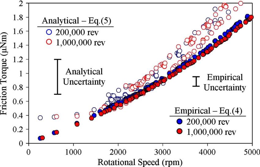
McCARTHY et al.: DYNAMIC FRICTION AND WEAR IN A PLANAR-CONTACT ENCAPSULATED MICROBALL BEARING                                                              265

Fig. 2. Conceptual schematics of the previously reported microturbine, show-
ing (a) the point-contact encapsulated microball bearing and (b) the tangential-
flow microturbine [21], [22].

                                                                                              Fig. 4. Microturbine fabrication process flow.

                                                                                                                              III. F ABRICATION
                                                                                                 The microturbine fabrication process consists of wafer-level
                                                                                              construction of encapsulated rotors followed by die-level tem-
                                                                                              porary bonding of a capping layer to create internal flow paths.
                                                                                              First, the microball housing is defined with a nested deep
                                                                                              reactive ion etch in a pair of low thickness variation (< 2 µm)
                                                                                              silicon wafers [Fig. 4(a) and (b)]. The inner and outer radii of
                                                                                              the bearing are 4.910 and 5.205 mm, respectively, creating a
                                                                                              295-µm-wide bearing housing. A 2-µm-thin gold/tin bonding
                                                                                              layer is evaporated through a shadow mask, and approximately
                                                                                              90 microballs are placed in the circumferential bearing housing
                                                                                              [Fig. 4(c)], filling roughly 85% of the race. This was found to
Fig. 3. Microturbine design showing the stator vane and rotor blade geome-
                                                                                              be an acceptable compromise between the minimum number
tries in their respective absolute and relative frames of reference.                          of microballs required to secure the rotor using encapsula-
                                                                                              tion (51% of the race) and the maximum number where ball
silicon race and steel microballs. Planar contact between the                                 jamming becomes a predominant failure mode (100% of the
microballs and the housing reduces stress concentrations and                                  race). The microballs (Thompson Precision Balls) are grade
minimizes raceway deformations, as compared to the point-                                     ten ball bearings made from 440C stainless steel with a di-
contact design. Similarly, the device presented in this paper                                 ameter of 285 ± 0.25 µm. The wafers are eutectically bonded
uses a radial in-flow microturbine design [Fig. 1(b)] as com-                                 [Fig. 4(d)] using the method described in detail by Waits et al.
pared to the previously reported tangential-flow configuration                                [22]. The variation in the deep etch for each side of the ball
[Fig. 2(b)]. As a result, the turbine is actuated axisymmetrically,                           housings is ±2.5 µm (at a depth of 145.5 µm), and the housing
evenly distributing the predominantly axial load supported by                                 width was measured to vary up to ±2 µm. Including the
the microballs over flat contacting surfaces, reducing both                                   estimated misalignment of the wafers [22] and the bonding
friction and wear.                                                                            layer thickness, the resulting encapsulated microball housing
   The microturbine was designed, assuming incompressible                                     is 295 ± 5 µm deep × 295 ± 7 µm wide, leaving 5–15 µm of
laminar flow and using a simple velocity-triangle method [24],                                vertical and 3–17 µm of lateral play between the balls and the
where the resulting blade geometry and design parameters                                      rectangular housing. The wafer stack is diced, and individual
are shown in Fig. 3. A design speed of 100 000 r/min at a                                     die is deep-etched using patterned SiO2 masks to define the
flow rate of 6 slm was chosen, providing 0.5 W of mechanical                                  100-µm-tall turbine blade and speed bump structures as well
power. Specifically, the maximum flow velocities and tip                                      as to release the rotor [Fig. 4(e)]. The SiO2 hard masks are
speeds were kept well below sonic conditions (< 50 m/s) to                                    defined in each wafer at the very beginning of the fabrication
meet the assumption of incompressible flow. The microturbine                                  process and have been omitted from Fig. 4.
presented here is a convenient actuation mechanism used to                                       A silicon capping layer is created with a 25-µm recess
characterize the novel microball bearing. Accordingly, no                                     to provide 10–20 µm of tip clearance for the spinning rotor
attempts were made to optimize the turbine design, and the                                    blades [Fig. 4(f)], while a through-etch is used to define inlet
only requirement imposed was the ability to span the range of                                 and outlet ports [Fig. 4(g)]. Finally, the released rotor and
desired rotor speeds.                                                                         capping layer are bonded using a temporary photoresist layer

                Authorized licensed use limited to: IEEE Xplore. Downloaded on April 13, 2009 at 13:01 from IEEE Xplore. Restrictions apply.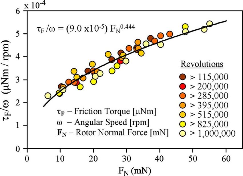
266 JOURNAL OF MICROELECTROMECHANICAL SYSTEMS, VOL. 18, NO. 2, APRIL 2009
pressure. To actuate the turbine, compressed nitrogen is pro-
vided through the topside manifold, while an optical displace-
ment probe tracks the rotation of speed bump structures. The
optical displacement sensor (Fig. 6) is located directly above
the 12 etched speed bump structures [Fig. 1(d)] at the central
exit of the microturbine. As the rotor spins, the sensor outputs a
50% duty-cycle square wave with a frequency 12 times higher
than the rotational speed of the turbine. The rotor speed is cal-
culated in real time using LabVIEW via a fast Fourier transform
(FFT) of the optical probe signal. Flow rate and pressure drop
for both the turbine and thrust plenum are also recorded in Lab-
VIEW. During spin-down testing, the measured thrust plenum
flow rate was below the sensitivity of the mass flow meter
(< 100 sccm) and more than an order of magnitude less than
the turbine flow rates. It is therefore assumed that leakage
from the thrust plenum has a negligible effect on the turbine.
For spin-down testing, raw data from the optical probe are
reduced to obtain angular position versus time; this is due to
Fig. 5. Schematic showing (a) the microturbine cross section and (b) the the insufficient sampling rate of the LabVIEW-FFT scheme.
experimental operation of the device indicating flow paths for the turbine and
thrust plenum. While all tests were performed at ambient temperature and
humidity, the bearing and turbine structures were actuated using
dry nitrogen, and it is assumed that the results reported here
represent bearing friction at 0% relative humidity.
V. R ESULTS AND D ISCUSSION
A. Microturbine Performance
By using the packaging scheme shown in Figs. 5 and 6,
the microturbine has been characterized up to 10 000 r/min
and over 1 000 000 revolutions. While this packaging approach
allows for independent control of normal and rotational forces
during spin-down testing, the two are coupled during turbine
actuation. As turbine flow passes over the rotor periphery
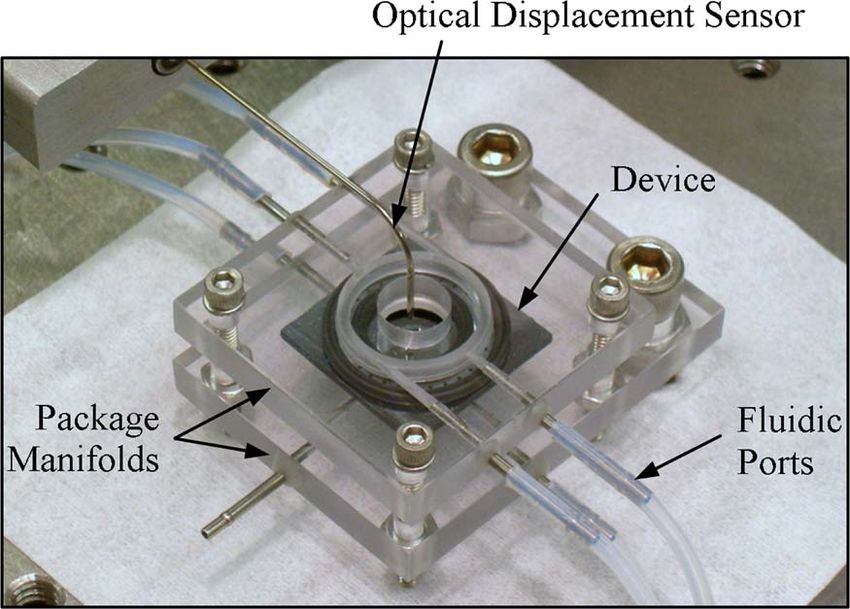
Fig. 6. Photograph of a packaged microturbine being tested. [Fig. 5(b)], the underside is pressurized, resulting in a net
upward normal force, without the addition of thrust plenum
[Fig. 4(h) and (i)]. As a result, the capping layer can be de- flow. Rotational speed, normal force, and turbine flow rate are
bonded between tests to examine the turbine and bearing struc- shown in Fig. 7 as a function of device inlet pressure, in the
tures. The overall device dimensions are 23 mm × 23 mm × absence of thrust plenum leakage flow through the bearing.
1.5 mm. Fig. 7(a) shows alternate paths for increasing and decreasing
actuation at low speeds. This can be attributed to a variety of
factors, the simplest of which is the higher static than dynamic
IV. E XPERIMENTAL A PPARATUS
friction associated with rolling contact. Starting from rest, the
Figs. 5 and 6 show schematic representations of the device microballs require a larger force (and, therefore, turbine inlet
cross section and operation, and a packaged device being pressure and flow) to initiate rolling, as compared to microballs
tested. Complete characterization of dynamic friction in the already in motion. When the turbine is decelerated, it maintains
planar-contact encapsulated microball bearing requires inde- rotation at a driving pressure below the start-up pressure. In
pendent control of bearing speed and thrust load. The decou- addition, variations in the slide-to-roll ratio of the microballs
pling of speed and load during spin-down testing is achieved could play a significant role. The slide-to-roll ratio of the
using a hydrostatic thrust plenum defined by the packaging as- microballs is unknown for all ranges of operation, and it is
sembly. The microfabricated turbine is packaged between two plausible that starting from rest, a larger slide-to-roll ratio
plastic manifolds using rubber o-ring seals for fluid delivery leads to higher friction. Another possible contributor is a net
as well as compliant support. During operation, the bottom radial force on the rotor as a result of slightly asymmetric
side of the device is pressurized, resulting in a net upward loading conditions during start-up. Fig. 7(b) shows a linear
normal force that lifts the rotor into proper contact with the relationship between inlet pressure and rotor normal force,
ball bearings. A desired thrust load can be achieved during demonstrating the dependence of normal and rotational forces
spin-down testing by supplying thrust plenum flow through a during actuation. While the microturbines presented here have
high-sensitivity flow control valve and monitoring the backside been successfully actuated in excess of 50 000 r/min, device
Authorized licensed use limited to: IEEE Xplore. Downloaded on April 13, 2009 at 13:01 from IEEE Xplore. Restrictions apply.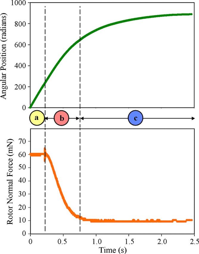
McCARTHY et al.: DYNAMIC FRICTION AND WEAR IN A PLANAR-CONTACT ENCAPSULATED MICROBALL BEARING                                                                          267

                                                                                              Fig. 8. Effect of wear debris on performance after prolonged operation. After
                                                                                              each data set, the device is cleaned and returns to the expected behavior.

                                                                                              of the characterization curves in Fig. 7(a)–(c) was collected
                                                                                              after ultrasonic cleaning. This suggests that while wear debris
                                                                                              limits the device endurance (the duration of time before the
                                                                                              onset of contamination, as shown in Fig. 8), wear itself (the
                                                                                              geometric deviation from the as-fabricated state) has little effect
                                                                                              on performance in the clean state [Fig. 7(a)–(c)]. This is a
                                                                                              counterintuitive result and would suggest that the wear particles
                                                                                              contaminating the microball housing are not being generated
                                                                                              from the load-bearing contact interfaces. This hypothesis will
                                                                                              be discussed further in a subsequent section.

                                                                                              B. Spin-Down Friction Testing
                                                                                                 Comprehensive characterization of dynamic bearing friction
                                                                                              is achieved through spin-down testing using the backside thrust
                                                                                              plenum [Fig. 2(b)] to achieve a desired rotor normal force. The
                                                                                              spin-down response of the microturbine can be separated into
                                                                                              three distinct stages, as shown in Fig. 9. Initially, the turbine is
                                                                                              spinning at a constant speed (∼10 000 r/min) corresponding to
Fig. 7. Turbine operating curves for (a) rotational speed, (b) rotor normal
force, and (c) turbine flow rate as a function of inlet pressure, with no thrust
                                                                                              a linear increase in angular position and an elevated constant
plenum flow.                                                                                  thrust force (stage a). Then, the turbine flow is shut off, and
                                                                                              the thrust force decreases dramatically as the rotor begins to
characterization has been restricted to 10 000 r/min. This value                              slow down (stage b). Finally, stage c corresponds to the period
was chosen to limit the range of rotor normal forces to those                                 after the thrust load equilibrates to within 10% of the preset
expected in bottom-drive electrostatic micromotors of the same                                desired value. Spin-down data are acquired during stage c.
size [18], [19]. In doing so, the friction and wear studies                                   An optical probe measures the angular position θ as the rotor
presented here will more closely represent the actual operating                               decelerates under a prescribed constant normal force provided
conditions, without excessively loading the bearing. When the                                 by the thrust plenum. The normal force is calculated as the
devices are actuated above 50 000 r/min, the increase in rotor                                product of the rotor area and the measured backside pressure.
normal force, coupled with the increase in speed, leads to                                    Spin-down friction testing is conducted immediately following
dramatic wear and abrupt failure of the devices.                                              ultrasonic cleaning of the device. It requires 2–3 min of turbine
   Fig. 8 shows the results of continuous operation, where the                                operation and less than 20 000 revolutions for each interval
turbines are actuated with 0.25 lbf/in2 of driving pressure,                                  considered. It is therefore assumed that the effects of wear
resulting in 2 slm of flow and 30 mN of normal force. The                                     debris are negligible over these durations as would be suggested
rotational speed is seen to decrease after an initial period                                  by the results shown in Fig. 8.
of consistent operation. This behavior has been attributed to                                    In addition, it is assumed that fluidic losses in the microtur-
the buildup wear debris, slowing the rotor due to increased                                   bine are small compared to bearing friction. Reynolds numbers
friction associated with particle contamination. Accordingly,                                 based on blade height and tip speed at the rotor periphery vary
the device was periodically cleaned in an acetone bath with                                   from 1 to 25 during spin-down testing. At such low Reynolds
ultrasonic agitation to remove wear particles. After ultrasonic                               numbers, skin friction effects can be assumed dominant over
cleaning, the turbine performance returns to the expected be-                                 pressure drag [25]. Under the assumption of fully developed
havior, showing longer operation with increased revolutions;                                  coquette flow through the turbine blade tip clearances and on
this implies a decreasing wear rate over time. Each data set                                  the underside of the rotor, it is estimated that viscous friction in

                Authorized licensed use limited to: IEEE Xplore. Downloaded on April 13, 2009 at 13:01 from IEEE Xplore. Restrictions apply.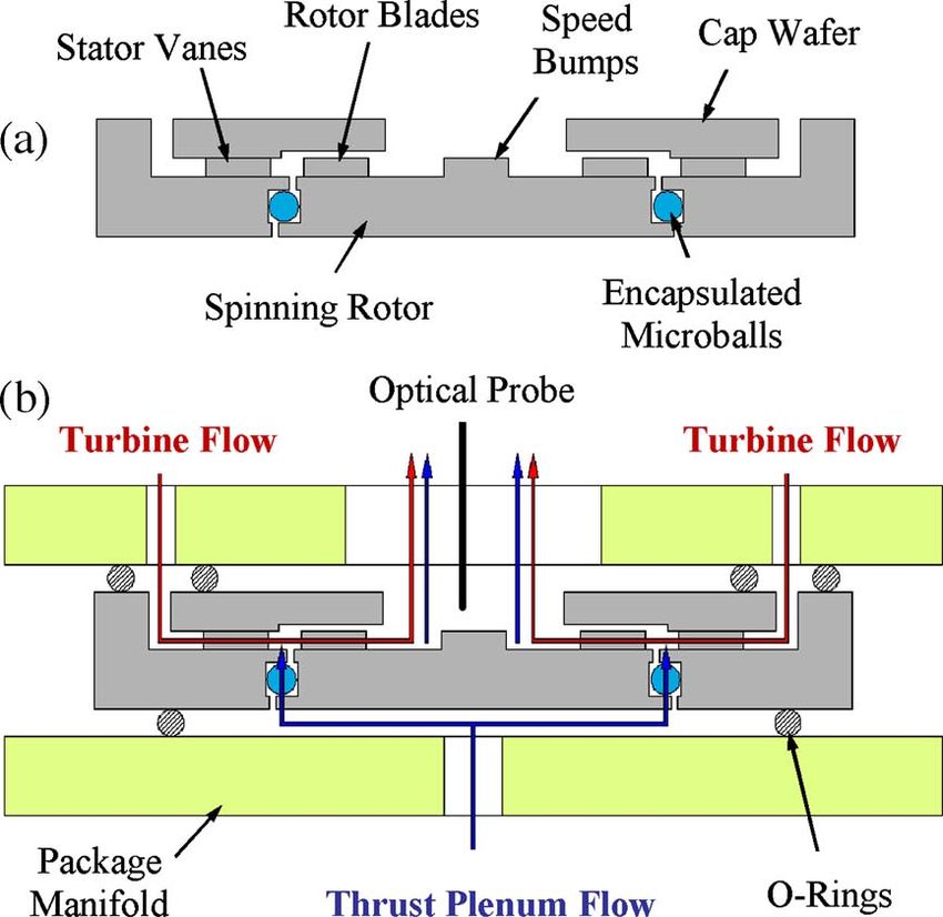
268                                                                                      JOURNAL OF MICROELECTROMECHANICAL SYSTEMS, VOL. 18, NO. 2, APRIL 2009

                                                                                              Fig. 11. Friction torque constant as a function of rotor normal force at various
                                                                                              intervals, showing good agreement with a power-law relation up to 1 000 000
                                                                                              revolutions.

                                                                                              would be expected. These position versus time data sets fit well
                                                                                              to an exponential function of the form

                                                                                                                               θ = A(1 − e−Bt )                           (1)

                                                                                              (with coefficients A and B). The result is a linear relationship
                                                                                              between angular acceleration (θ̈) and angular velocity (θ̇)
Fig. 9. Spin-down data acquisition procedure. (a) The turbine is spun at a
constant speed of 10 000 r/min. (b) The turbine flow is shut off, and the speed
and normal force decrease. (c) The normal force equilibrates to the preset value;                                                    θ̈ = −B θ̇                           (2)
spin-down data are acquired during this stage as the rotor decelerates under a
specified constant normal force.                                                              and, therefore, a linear relationship between friction torque,
                                                                                              calculated as the product of the angular acceleration and rotor
                                                                                              mass moment of inertia (τF = I θ̈), and bearing speed (ω = θ̇).
                                                                                              Accordingly, each spin-down at a constant normal force (FN )
                                                                                              corresponds to a single ratio of friction torque to rotational
                                                                                              speed
                                                                                                                           τF
                                                                                                                              = |I · B| = f (FN )                         (3)
                                                                                                                            ω
                                                                                              (referred to here as the friction torque constant) where I is
                                                                                              the rotor mass moment of inertia and B is the coefficient
                                                                                              determined from numerical fitting.
                                                                                                 This testing and data reduction scheme is repeated sequen-
                                                                                              tially at various intervals up to 1 000 000 revolutions for normal
Fig. 10. Spin-down trajectory data for several normal loads fit to an exponen-                loads from 10 to 50 mN. These loads correspond to the range of
tial function with constants A and B, resulting in a linear relationship between              expected values in next-generation electrostatic and magnetic
deceleration and speed.                                                                       micromotors and microgenerators supported on microball bear-
                                                                                              ings [19]. The dependence of friction torque constant (τF /ω)
these components makes up less than 5% of the total measured                                  on the normal load (FN ) is shown in Fig. 11 for intervals
friction torque. This is due to relatively large rotor blade tip                              up to 1 000 000 revolutions. Dynamic friction torque has been
clearance gaps (> 10 µm), small tip clearance areas, and the                                  characterized for speeds and loads of 250–5000 r/min and
large distance between the rotor underside and the package                                    10–50 mN, respectively, corresponding to 0.0625–2.5 µN · m
(1.5 mm). Viscous effects occurring within the actual microball                               of friction torque. By using these results, the microball bearings
housing are considered small but inherent components of bear-                                 exhibit velocity and load-dependent coefficients of dynamic
ing friction and should be included in the characterization.                                  friction (defined as the ratio of tangential friction force to
It is therefore assumed that fluidic effects comprise a small                                 normal force) varying from 0.0005 (at 250 r/min and 50 mN)
percentage of the total resistance and the friction measurements                              to 0.025 (at 5000 r/min and 10 mN). Over the operating ranges
reported here are representative of the bearing itself.                                       considered here, the dynamic friction torque was found to fit
   To characterize the effects of speed and load on dynamic                                   well to an empirically derived power-law model using two
bearing friction, the testing procedure is repeated for several                               modeling constants (C and D). A linear relationship between
normal loads. Fig. 10 shows spin-down data acquired at several                                friction torque and speed has been observed, while friction
thrust forces, showing faster spin-down at higher loads, as                                   increases as the normal force to the power of D = 0.444. The

              Authorized licensed use limited to: IEEE Xplore. Downloaded on April 13, 2009 at 13:01 from IEEE Xplore. Restrictions apply.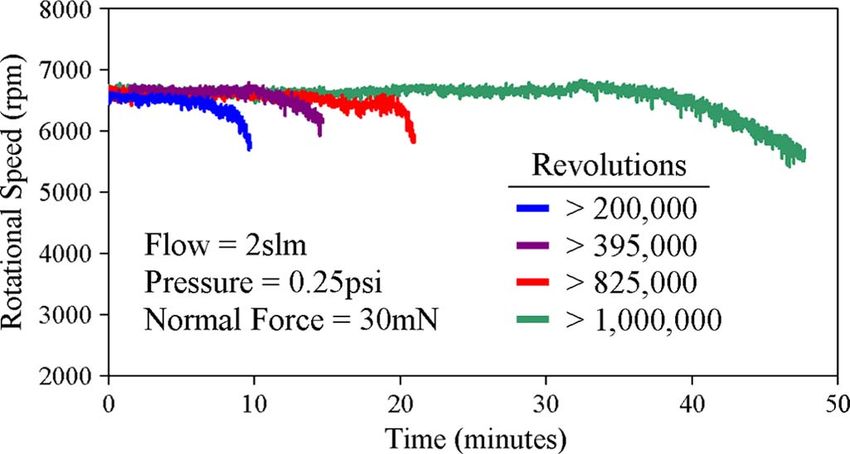
McCARTHY et al.: DYNAMIC FRICTION AND WEAR IN A PLANAR-CONTACT ENCAPSULATED MICROBALL BEARING                                                                269

                                                                                             outer-diameter deep-groove and angular-contact bearings, typ-
                                                                                             ical manufacturer speed limitations are from 25 000 r/min
                                                                                             (DN = 250 000) to 60 000 r/min (DN = 600 000) and in-
                                                                                             crease with a reduction in size. These values are representa-
                                                                                             tive of average bearing performance, and high-speed bearings
                                                                                             (DN > 1 000 000) are not uncommon.
                                                                                                In this paper, the raceway is completely filled with the balls
                                                                                             and no cage is used; this is due to limitations in microfabrication
                                                                                             capabilities. The inclusion of liquid lubricants into microbear-
                                                                                             ings is likely problematic due to high static friction, large
                                                                                             evaporation rates, and the complexity of maintaining constant
                                                                                             lubrication over long operating times. In addition, the ratio
                                                                                             of ball diameter to rotor diameter for the microball bearings
                                                                                             (0.0285) is notably lower than those in macrofabricated thrust-
Fig. 12. Empirical modeling constants from spin-down friction tests, equili-                 loaded ball bearings where values around 0.1–0.2 are typical
brating after an initial period of wear.                                                     [26]. Nevertheless, the microball bearings have been demon-
                                                                                             strated at speeds and rolling resistances comparable to the
constant of proportionality in the empirical power-law model is                              ranges seen in typical macrofabricated bearing mechanisms of
C = 9 × 10⁻⁵ µN · m/mN0.444 · r/min, such that                                               the same size. The microball bearings have been character-
                     τF = (9.0 × 10⁻⁵ )FN0.444 ω.                                   (4)      ized up to 10 000 r/min (DN = 100 000) with peak measured
                                                                                             speeds of 50 000 r/min (DN = 500 000). The coefficient of
   Fig. 12 shows the evolution of these modeling constants at                                friction (defined as the ratio of tangential friction force to
every interval. After an initial period of “run-in”, consistent                              normal force) has been measured to be as low as 0.0005 for
results from 100 000 to 1 000 000 revolutions are observed                                   low-speed high-load operation, while typical values in the range
corresponding to the empirical friction model of (4).                                        of 0.0001–0.0005 are reported for conventional bearings [26].
   These results show that 0.025 mW of power is dissipated at                                Long-term operation of microball bearings has yet to be
1000 r/min under a normal load of 10 mN. If it is assumed                                    demonstrated, and this will most likely require technological
that the model given by (4) holds true for higher speeds, then                               advancements similar to those used in conventional bearings,
2.5 and 250 mW will be dissipated at speeds of 10 000 and                                    namely, tailoring the geometry and materials of the contact
100 000 r/min, respectively. This demonstrates the amount of                                 interfaces. While it is unlikely that MEMS-fabricated bearings
power needed to be transferred at various speed ranges for such                              will surpass the performance of macrofabricated bearings, these
bearings to be efficient support mechanisms. Electrically actu-                              results show a promise for their development as stable and
ated devices (motors, pumps, etc.) designed to operate around                                reliable support mechanisms capable of being integrated with
10 000 r/min will require up to several milliwatts of power for                              complex microsystems.
efficient operation, and turbine-driven devices (microturbogen-
erators) will require watt-level power. While these ranges are                               D. Comparison to MEMS Bearings
acceptable for next-generation MEMS devices, the developed
platform will be used to investigate and reduce bearing friction                                The microball-bearing performance can be compared to gas-
by minimizing normal load and depositing tribological hard                                   lubricated MEMS bearings via the viscous torque constant, a
coatings.                                                                                    direct analogy to the friction torque constant described here
                                                                                             (τF /ω), where viscous drag resists rotation rather than rolling
                                                                                             friction. The electric induction micromotor supported on fluid
C. Comparison to Conventional Ball Bearings
                                                                                             film bearings developed by Livermore et al. [12] operated at a
   Bearings fabricated using macroscale techniques have been                                 maximum tip speed of 11.5 m/s, and a viscous torque constant
optimized for decades and use a variety of advanced materials,                               of (5.9 ± 0.96) × 10−5 µN · m/r/min was measured using ex-
components, geometries, and lubricants. While conventional                                   perimental spin-down testing. Fréchette et al. [13], [14] have
ball bearings have several key differences to those presented                                reported viscous torque constants as low as 2 × 10⁻⁵ µN ·
here, they can be compared to MEMS-fabricated bearings on                                    m/r/min in microfabricated induction motors and turbomachin-
the basis of size, speed, and friction. Speed limitations are                                ery through spin-down characterization and theoretical calcu-
dependent on many factors, such as the bearing materials,                                    lations. This paper shows friction torque constants as low as
raceway design, cage material, lubrication type, tolerance, and                              (22.5 ± 5) × 10−5 µN · m/r/min, for a normal force of 10 mN,
loading conditions. In most ball-bearing designs at the scale                                with a maximum tip speed of 5.2 m/s. It should be noted
developed in this paper, the bearing contains a ball cage to                                 that the gas-lubricated viscous torque constant constitutes the
isolate the balls from contacting each other. In addition to the                             total viscous drag, including effects from the journal and thrust
cage, bearings of this size usually use oil or grease lubrication.                           bearings as well as the electrostatic motor and other surfaces
A well-established means of defining bearing speed is the DN                                 in close proximity with the rotor. Accordingly, an electrosta-
value, the product of bearing diameter (in millimeters) and                                  tic microball-bearing-supported device would have additional
the rotational speed (in revolutions per minute). For 10-mm                                  components of drag not considered in this paper, such as those

               Authorized licensed use limited to: IEEE Xplore. Downloaded on April 13, 2009 at 13:01 from IEEE Xplore. Restrictions apply.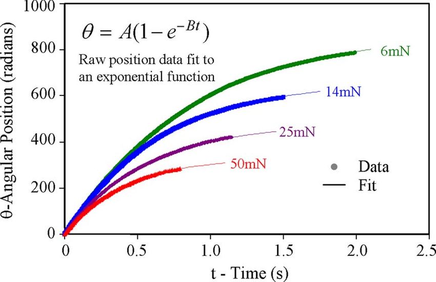
270                                                                                    JOURNAL OF MICROELECTROMECHANICAL SYSTEMS, VOL. 18, NO. 2, APRIL 2009

acting over small gaps associated with electrostatic actuation or
generation.
   While the achievement of friction characteristics comparable
to those demonstrated in fluid film bearings may not be possi-
ble, this paper demonstrates a notable decrease in fabrication
and operation complexities as well as an increase in robustness
as compared to air bearings. The microturbines reported here
have been fabricated using relatively simple processes with
nearly 100% yield and are inherently immune to the dramatic
and catastrophic failures reported in gas-lubricated systems.
While contamination due to excessive wear has been observed,
the devices do not suffer from stability issues associated with
natural frequency as in air bearings. Similarly, the bearing
considered here shows a decrease in coefficient of dynamic
friction of several orders of magnitude as compared to direct-                              Fig. 13. Comparison of friction torque calculated using experimental data
contact sliding bearings operated at comparable speeds [6].                                 with both the analytical and empirical models of (5) and (4), respectively.
Optimized microball bearings using tribological coatings and
axially balanced rotors are envisioned for maximum operating                                   In macroscale turbomachinery, the exit flow deviations (δθ2s
speeds of 100 000–200 000 r/min, tips speeds of less than                                   and δθ2r ) depend on blade geometry, inlet incidence angle, and
100 m/s, and friction torques on the order of 1–10 µN · m.                                  flow Mach number. In addition, Lee et al. [27], [28] have shown
This is a notably lower speed than that achieved using the                                  a strong dependence between flow deviation and Reynolds
fluid film bearings developed by Fréchette et al., demonstrating                            number (Re) in microturbomachinery, for 100 < Re < 1000,
1 400 000 r/min and tip speeds of 300 m/s [14].                                             where Re is defined using the chord length and inlet conditions.
                                                                                            By using computational fluid dynamics (CFD), Lee has shown
                                                                                            that for a rotor blade cascade with a solidity and chamber
E. Comparison to Analytic Predictions
                                                                                            comparable to the microturbine in this paper, the exit flow angle
   An empirical model for bearing friction has been developed                               varies nonlinearly up to ±10% of the designed blade angle,
for a range of speeds and loads by directly measuring rotor                                 over the range of Re considered here (100 < Re < 1000).
deceleration and, therefore, friction torque. An alternative indi-                          The power delivered to the turbine will be altered by flow
rect method of friction modeling could be derived analytically                              deviations as well as several other factors creating variations
from the turbine torque, although it suffers from fundamental                               during actual operation. As the boundary layer grows, the
uncertainties requiring complex and impractical computational                               effective blade height will be reduced by flow blockage. In
modeling. The comparison of these two techniques will be                                    addition, tip clearance flow between the rotor blades and the
presented in this section.                                                                  capping wafer will reduce the total effective mass flow rate
   Neglecting the effects of viscous losses, the torque applied                             and, therefore, the torque applied to the rotor. These phenomena
to the rotor from the working fluid is balanced by friction                                 have complex relationships with various flow parameters and
generated in the microball bearing. Accordingly, the friction                               therefore change with operating conditions. Typically, CFD is
torque can be evaluated using theoretical means. Applying the                               necessary to accurately model these effects.
conservation of angular momentum, the torque is equal to the                                   In the absence of comprehensive CFD modeling, the the-
time rate of change of angular momentum in a streamtube                                     oretical approximation for friction torque in (6) cannot be
flowing through the device [24], expressed analytically as                                  confidently implemented to characterize the microball bearings,
                                                                                            due to variations arising in the actual flow. For comparison
                       τF = ṁ(rL VL − rT VT )                                     (5)      purposes, friction torque has been calculated using both the
                                                                                            developed empirical model [see (4)] and the analytical model
where ṁ is the mass flow rate, r is the radial location, and                               [see (6)] and is shown in Fig. 13. Experimental measurements
V is the tangential velocity of the fluid in the absolute frame,                            of rotational speed, mass flow rate, and normal force were
where the subscripts L and T represent the rotor blade leading                              used to calculate torque, while the flow angles were assumed
and trailing edges, respectively. Defining the absolute tangential                          to be identical to the as-fabricated blade angles (θ2s and θ2r
flow velocities (VL and VT ) in terms of mass flow rate, rotor                              in Fig. 3). In these calculations, the analytical uncertainty is
speed, and blade geometry, (5) can be reduced to                                            based on ±10% exit flow deviations from the defined blade
          !                                                     "                           angles, and the empirical uncertainty is based on the error in the
             ṁ
τF = ṁ          (tan(θ2s + δθ2s ) + tan(θ2r + δθ2r )) − rT2 ω                              power-law curve fitting shown in Fig. 11. This analysis does not
            2πρh
                                                              (6)                           take into consideration the effects of blockage or tip clearance
                                                                                            flow. Fig. 13 shows the friction torque calculated after 200 000
where ρ is the fluid density, h is the blade height, θ2s and θ2r are                        and 1 000 000 revolutions with negligible variations between
the stator vane and rotor blade exit angles (using the convention                           the two. It can be seen that the analytically calculated torque
defined in Fig. 3), and δθ2s and δθ2r are the deviations of the                             has a larger scatter as compared to the empirical. This is a
actual flow velocities from the ideal blade angles.                                         product of fluctuations in the mass flow measurements used

            Authorized licensed use limited to: IEEE Xplore. Downloaded on April 13, 2009 at 13:01 from IEEE Xplore. Restrictions apply.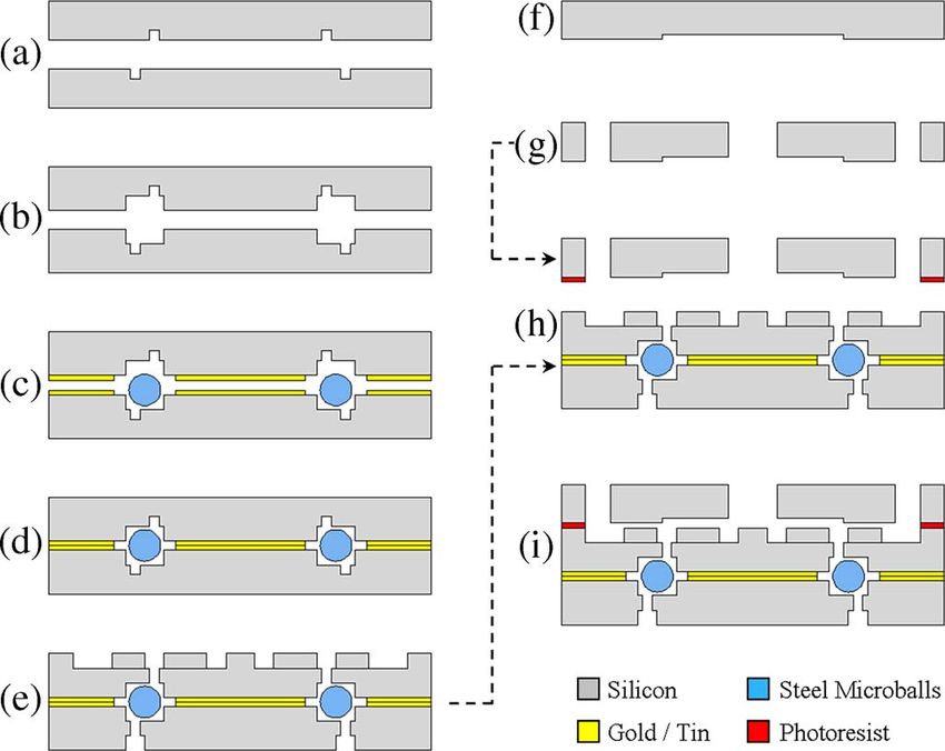
McCARTHY et al.: DYNAMIC FRICTION AND WEAR IN A PLANAR-CONTACT ENCAPSULATED MICROBALL BEARING                                                                     271

to calculate the analytical results; the empirically calculated
values are based on speed and pressure measurements alone
which have much smaller fluctuations. The variations between
the analytical and empirical results are attributed to an inability
to predict, among other things, exit flow deviations, blockage,
and tip clearance flow. These results show general agreement
between the two approaches, validating the empirical modeling
approach based on spin-down testing. They simultaneously
address the large uncertainty in an analytically derived friction
measurement technique. The larger predicted values of torque
in Fig. 13 are consistent with the effects of tip clearance
and flow deviation, where less mass flow rate is being turned
by the rotor blades and producing torque. This variability in
the analytic model highlights the necessity of the empirically
                                                                                            Fig. 14. SEM image of the rotor periphery identifying the race surface and
derived model developed and the spin-down approach used in                                  the sidewall bond interface locations exhibiting wear.
this paper.
                                                                                            to be less than 100 nm. This is a marked improvement from
                                                                                            the earlier point-contact designs [21], [22], where over 12 µm
F. Wear
                                                                                            of wear was seen for similar loading conditions. The resistance
   The effects of wear are equally as important as friction to the                          to wear is critical in the realization of rotary micromotors and
realization of microball-bearing-support mechanisms for rotary                              microgenerators where a consistent and known gap between the
MEMS devices. Accordingly, the microturbine was disassem-                                   rotor and electrical/magnetic stator elements is crucial.
bled to examine the state of wear on the microballs and within                                 Fig. 15(c) and (d) shows the bond interface on the bearing
the bearing housing upon completion of the previously de-                                   housing sidewall for unworn and worn devices. While the
scribed experiments. Wear on the balls themselves was virtually                             design of this device addressed the reduction of wear by using
unnoticeable when examined using SEM imaging and appeared                                   a planar-contact geometry, insufficient consideration was given
only as a smoothing of the as-manufactured stainless steel balls.                           to wear on the housing sidewall. The wafer-level eutectic bond-
This is likely due to the relatively large total surface area of the                        ing procedure [Fig. 4(d)] used to encapsulate the microballs
microballs as compared to the raceways. As the rotor spins, the                             led to a poorly placed bond interface. While radial loads are
balls are free to rotate in all directions, and only a small fraction                       significantly lower than axial loads, the nature of the free edges
of the available surface area is in contact at any given instant.                           at the bond interface creates stress concentrations, resulting in
The silicon housing, however, experiences repeated loading and                              excessive wear and particle generation. Fig. 15(c) shows the
unloading over a much smaller and constant area.                                            unworn bond interface, and Fig. 15(d) shows the bond interface
   The planar-contact raceway design, shown schematically in                                after 1 000 000 revolutions.
Fig. 1, has four points of possible contact: first and foremost,                               The SEM images in Fig. 15 shed light on the counterintuitive
the race surfaces on both the rotor and stator, which support                               results discussed in the Microturbine Performance section,
the axial thrust load, and second, the sidewalls of the bearing                             where wear particles slowed the turbine but had virtually no
housing, which support radial loads. Fig. 14 shows a SEM                                    effect on performance after being cleaned. This suggests that
image of the rotor periphery where the turbine rotor blades                                 rolling friction at the race surfaces is the predominant cause
can be seen, along with the identification of these two critical                            of friction torque and therefore dictates turbine performance.
locations exhibiting wear. Due to the symmetric nature of the                               These surfaces showed negligible wear, and therefore, negli-
encapsulated bearing housing, a wafer bond interface exists                                 gible change in performance was seen when operated in the
directly at the point of contact between the microballs and                                 clean state. Chipping and wearing at the sidewall bond interface
the housing sidewall. Fig. 15 shows the unworn and worn                                     generates the wear debris, slowing the turbine after continuous
race surfaces and bond interfaces, where the worn device was                                operation, but has an insignificant effect on friction (and there-
actuated for over 1 000 000 revolutions at an average speed and                             fore performance) in the clean state, because it supports only
normal force of 6000 r/min and 30 mN, respectively.                                         minor radial loads.
   Fig. 15(a) and (b) shows the race surfaces (the primary                                     Based on the results presented here, a critical modification to
load-bearing surfaces used to support the normal thrust force)                              the bearing structure is being implemented in future designs.
for unworn and worn devices. As can be seen, an obvious                                     By simply adjusting the depths of the etches used to create
fabrication defect exists on the edge of this surface. This defect                          the bearing housing, the bond interface can be offset from the
is a product of the nested etches used to define the housing                                contacting microballs. This will greatly improve the endurance
in Fig. 4(a) and (b). The housing is designed such that the                                 and performance of the planar-contact encapsulated bearing.
microball contacts are far enough from the edge not to interfere
with this defect. A wear track less than 15 µm wide can be seen
                                                                                                                            VI. C ONCLUSION
in Fig. 15(b). While the wear track is visible in SEM imaging,
the depth was too small to measure using optical profilometry                                 Stable operation of a silicon microturbine supported on a
and, therefore, indistinguishable from the roughness, measured                              novel planar-contact encapsulated microball bearing has been

              Authorized licensed use limited to: IEEE Xplore. Downloaded on April 13, 2009 at 13:01 from IEEE Xplore. Restrictions apply.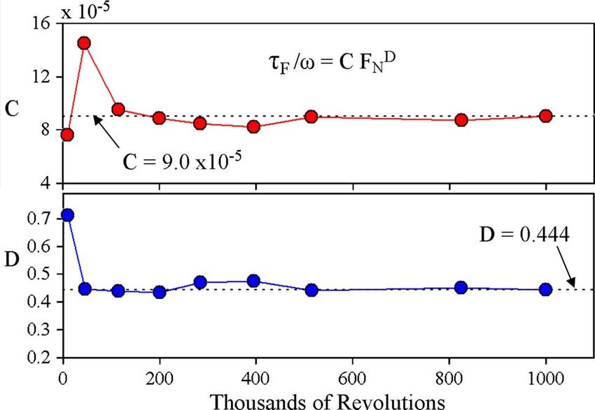
272                                                                                      JOURNAL OF MICROELECTROMECHANICAL SYSTEMS, VOL. 18, NO. 2, APRIL 2009

Fig. 15. Comparison of the bearing race surfaces and bond interfaces of an unworn device and a device after 1 000 000 revolutions at an average speed and
normal force of 6000 r/min and 30 mN, respectively. (a) Unworn race. (b) Worn race. (c) Unworn bond interface. (d) Worn bond interface.

demonstrated for over 1 000 000 revolutions at speeds, pressure                                      drive motors,” J. Vac. Sci. Technol. A, Vac. Surf. Films, vol. 8, no. 4,
drops, and flow rates of up to 10 000 r/min, 0.45 lbf/in2 , and                                      pp. 3614–3624, Jul. 1990.
                                                                                               [4]   M. Mehregany, S. D. Senturia, and J. H. Lang, “Friction and wear
3.5 slm, respectively. The devices and testing apparatus pre-                                        in microfabricated harmonic side-drive motors,” in Proc. Solid-State
sented here have enabled the first characterization and empirical                                    Sens., Actuators Microsyst. Workshop, Hilton Head Island, SC, 1990,
modeling of dynamic friction in microball bearings over oper-                                        pp. 17–22.
                                                                                               [5]   M. Mehregany, S. Senturia, and J. Lang, “Measurement of wear in
ating conditions relevant to the development of a wide range                                         polysilicon micromotors,” IEEE Trans. Electron Devices, vol. 39, no. 5,
of rotary PowerMEMS devices, corresponding to torques of                                             pp. 1136–1143, May 1992.
0.0625–2.5 µN · m, friction coefficients of 0.0005–0.025, and                                  [6]   V. R. Dhuler, M. Mehregany, and S. M. Phillips, “A comparative study
                                                                                                     of bearing designs and operational environments for harmonic side-
friction torque constants of 2.25–5.25 × 10⁻⁴ µN · m/r/min.                                          drive micromotors,” IEEE Trans. Electron Devices, vol. 40, no. 11,
This is the first demonstration of such a system, independently                                      pp. 1985–1989, Nov. 1993.
investigating the effects of speed and load, through the use of a                              [7]   U. Beerschwinger, R. L. Reuben, and S. J. Yang, “Frictional study of mi-
                                                                                                     cromotor bearings,” Sens. Actuators A, Phys., vol. 63, no. 3, pp. 229–241,
hydrostatic thrust plenum. This apparatus has provided quanti-                                       Dec. 1997.
tative and qualitative information on the nature and prominence                                [8]   S. Kumar, D. Cho, and W. Carr, “A proposal for electrically levitating
of friction and wear in microball bearings, leading to relevant                                      micromotors,” Sens. Actuators A, Phys., vol. 24, no. 2, pp. 141–149,
                                                                                                     Jul. 1990.
geometric design modifications. In addition, the device and                                    [9]   K. Komori and T. Yamane, “Magnetically levitated micro PM motors by
testing platform presented in this paper will be used to study                                       two types of active magnetic bearings,” IEEE/ASME Trans. Mechatronics,
the effects of humidity and hard coatings on friction and wear                                       vol. 6, no. 1, pp. 43–49, Mar. 2001.
                                                                                              [10]   A. H. Epstein, S. D. Senturia, O. Al-Midani, G. Anathasuresh, A. Ayon,
in microball bearings. The technologies presented here will act                                      K. Breuer, K.-S. Chen, F. F. Ehrich, E. Esteve, and L. Frechette, “Micro-
as the basis for developing robust drive and support mecha-                                          heat engine, gas turbine, and rocket engines—The MIT microengine
nisms for rotary microgenerators, motors, electric pumps, and                                        project,” presented at the 28th AIAA Fluid Dynamics Conf., Snowmass
                                                                                                     Village, CO, Jun. 1997.
turbopumps.                                                                                   [11]   F. F. Ehrich and S. A. Jacobson, “Development of high-speed gas bear-
                                                                                                     ings for high-power density microdevices,” ASME J. Eng. Gas Turbines
                           ACKNOWLEDGMENT                                                            Power, vol. 125, no. 1, pp. 141–148, Jan. 2003.
                                                                                              [12]   C. Livermore, A. Forte, T. Lyszczara, S. D. Umans, and J. H. Lang, “A
  The authors would like to thank N. Siwak for the SEM                                               high-power MEMS electric induction motor,” J. Microelectromech. Syst.,
                                                                                                     vol. 13, no. 3, pp. 465–471, Jun. 2004.
images contained in this paper.                                                               [13]   L. G. Fréchette, S. F. Nagle, R. Ghodssi, S. D. Umans, M. A. Schmidt,
                                                                                                     and J. H. Lang, “An electrostatic induction micromotor supported on gas-
                                                                                                     lubricated bearings,” in Proc. IEEE Microelectromech. Syst., Interlaken,
                                 R EFERENCES                                                         Switzerland, Jan. 21–25, 2001, pp. 290–293.
 [1] L.-S. Fan, Y.-C. Tai, and R. S. Muller, “IC-processed electrostatic micro-               [14]   L. G. Fréchette, S. A. Jacobson, K. S. Breuer, F. F. Ehrlich, R. Ghodssi,
     motors,” in IEDM Tech. Dig., San Francisco, CA, 1988, pp. 666–669.                              R. Khanna, C. W. Wong, X. Zhang, M. A. Schmidt, and A. Epstein, “High-
 [2] Y. C. Tai, L. S. Fan, and R. S. Muller, “IC processed micro-motors:                             speed microfabricated silicon turbomachinery and fluid film bearings,”
     Design, technology, and testing,” in Proc. IEEE Microelectromech. Syst.,                        J. Microelectromech. Syst., vol. 14, no. 1, pp. 141–152, Feb. 2005.
     Salt Lake City, UT, 1989, pp. 1–6.                                                       [15]   T.-W. Lin, A. Modafe, B. Shapiro, and R. Ghodssi, “Characterization
 [3] M. Mehregany, S. F. Bart, L. S. Tavrow, J. H. Lang, and S. D. Senturia,                         of dynamic friction in MEMS-based microball bearings,” IEEE Trans.
     “Principles in design and microfabrication of variable-capacitance side-                        Instrum. Meas., vol. 53, no. 3, pp. 839–846, Jun. 2004.

              Authorized licensed use limited to: IEEE Xplore. Downloaded on April 13, 2009 at 13:01 from IEEE Xplore. Restrictions apply.
McCARTHY et al.: DYNAMIC FRICTION AND WEAR IN A PLANAR-CONTACT ENCAPSULATED MICROBALL BEARING 273
[16] X. Tan, A. Modafe, and R. Ghodssi, “Measurement and modeling of C. Mike Waits (S’01–M’08) received the B.S. de-
dynamic rolling friction in linear microball bearings,” Trans. ASME, J. gree in physics from Salisbury University, Salisbury,
Dyn. Syst. Meas. Control, vol. 128, no. 4, pp. 891–898, Dec. 2006. MD, in 2000, and the M.S. and Ph.D. degrees in elec-
[17] N. Ghalichechian, A. Modafe, J. H. Lang, and R. Ghodssi, “Dynamic trical engineering from the University of Maryland,
characterization of a linear electrostatic micromotor supported on mi- College Park, in 2003 and 2008, respectively.
croball bearings,” Sens. Actuators A, Phys., vol. 136, no. 2, pp. 416–503, He joined the Sensors and Electron Devices Di-
May 2007. rectorate, U.S. Army Research Laboratory, Adelphi,
[18] N. Ghalichechian, A. Modafe, M. Beyaz, and R. Ghodssi, “Design, fab- MD, as an Electronics Engineer in 2004. His main
rication, and characterization of a rotary micromotor supported on mi- research interests include MEMS components and
croball bearings,” J. Microelectromech. Syst., vol. 17, no. 3, pp. 632–642, systems focused on power and energy generation
Jun. 2008. and conversion (power MEMS), MEMS tribology
[19] N. Ghalichechian, “Design, fabrication, and characterization of ro- and bearing mechanisms, and new microfabrication techniques.
tary variable-capacitance micromotor supported on microball bearings,” Dr. Waits was the recipient of the Physics Excellence Award from
Ph.D. dissertation, Univ. Maryland, College Park, MD, 2007. Salisbury University in 2000, the Graduate Assistance in Areas of National
[20] N. Ghalichechian, M. McCarthy, M. Beyaz, and R. Ghodssi, “Measure- Need (GAAN) Fellowship in 2001–2003, and Department of the Army Re-
ment and modeling of friction in linear and rotary micromotors supported search and Development Achievement Award for Technical Excellence in 2007.
on microball bearings,” in Proc. IEEE Microelectromech. Syst., Tucson,
AZ, Jan. 13–17, 2008, pp. 507–510.
[21] C. M. Waits, N. Jankowski, B. Geil, and R. Ghodssi, “MEMS rotary
actuator using an integrated ball bearing and air turbine,” in Proc. Int.
Conf. Solid-State Sens. Microsyst., Lyon, France, Jun. 10–14, 2007,
pp. 1131–1134.
[22] C. M. Waits, B. Geil, and R. Ghodssi, “Encapsulated ball bearings
for rotary micromachines,” J. Micromech. Microeng., vol. 17, no. 9,
pp. S224–S229, Sep. 2007.
[23] M. McCarthy, C. M. Waits, and R. Ghodssi, “Development of a hybrid
gas/ball bearing support mechanism for microturbomachinery,” in Proc.
Int. Workshop Micro Nanotechnol. Power Gen. Energy Convers., Freiburg,
Germany, Nov. 28–29, 2007, pp. 241–244.
[24] R. I. Lewis, Turbomachinery Performance Analysis. Hoboken, NJ:
Wiley, 1996.
[25] R. W. Fox and A. T. McDonald, Introduction to Fluid Mechanics.
Hoboken, NJ: Wiley, 1998.
[26] T. A. Harris and M. N. Kotzalas, Rolling Bearing Analysis: Essential
Concept of Bearing Technology. Boca Raton, FL: CRC Press, 2006.
[27] C. Lee, S. Arslan, and L. G. Fréchette, “Design principles and aerodynam-
ics of low Reynolds multi-stage microturbomachinery,” in Proc. ASME
Int. Mech. Eng. Congr. Expo., Anaheim, CA, Nov. 13–19, 2004. Reza Ghodssi (S’92–M’96) is the Herbert Rabin
[28] C. Lee, “Development of a microfabricated turbopump for a rankine vapor Distinguished Associate Professor and Director of
power cycle,” Ph.D. dissertation, Columbia Univ., New York, NY, 2006. the MEMS Sensors and Actuators Laboratory, De-
partment of Electrical and Computer Engineer-
ing, Institute for Systems Research, University of
Maryland (UMD), College Park. He is also affiliated
Matthew McCarthy received the B.S. degree in with the Fischell Department of Bioengineering, the
aerospace engineering from Syracuse University, Maryland NanoCenter, the University of Maryland
Syracuse, NY, in 2002 and the M.S. and Ph.D. Energy Research Center, and the Department of Ma-
degrees in mechanical engineering from Columbia terials Science and Engineering at UMD. He is the
University, New York, NY, in 2004 and 2006, author or coauthor of more than 62 scholarly publi-
respectively. cations and the Coeditor of the Handbook of MEMS Materials and Processes
He was a Postdoctoral Research Associate with (in press, 2009). He is an Associate Editor of Biomedical Microdevices. His
the MEMS Sensors and Actuators Laboratory, De- research interests are in the design and development of microfabrication tech-
partment of Electrical and Computer Engineer- nologies and their applications to micro/nanodevices and systems for chemical
ing, Institute for Systems Research, University of and biological sensing, small-scale energy conversion, and harvesting.
Maryland, College Park, from 2007 to 2008. He Dr. Ghodssi is a member of the American Vacuum Society, the Materials
is currently a Postdoctoral Associate with the Department of Mechanical Research Society, the American Society for Engineering Education, and the
Engineering, Massachusetts Institute of Technology, Cambridge. His research American Association for the Advancement of Science. He is the Cofounder
interests are in the field of emerging power MEMS and microcooling tech- of MEMS Alliance in the greater Washington area. He is an Associate Editor
nologies. His current efforts are focused on the development of ball-bearing- of the Journal of Microelectromechanical Systems. He was the recipient of
supported rotary micromachines, tribological characterization of microscale the 2001 UMD George Corcoran Award, the 2002 National Science Founda-
rolling contacts, nanostructured energy storage devices, sensors and actuators, tion CAREER Award, and the 2003 UMD Outstanding Systems Engineering
and compact cooling systems. Faculty Award.
Authorized licensed use limited to: IEEE Xplore. Downloaded on April 13, 2009 at 13:01 from IEEE Xplore. Restrictions apply.You can also read