Sensing of joint and spinal bending or stretching via a retractable and wearable badge reel - Nature
←
→
Page content transcription
If your browser does not render page correctly, please read the page content below
ARTICLE
                  https://doi.org/10.1038/s41467-021-23207-8                 OPEN

                  Sensing of joint and spinal bending or stretching via
                  a retractable and wearable badge reel
                  Chengyu Li 1,2,7, Di Liu1,3,7, Chaoqun Xu1,2, Ziming Wang1,3, Sheng Shu1,3, Zhuoran Sun4, Wei Tang1,2,3 ✉ &
                  Zhong Lin Wang 1,3,5,6 ✉
1234567890():,;

                  Human motions, such as joint/spinal bending or stretching, often contain information that is
                  useful for orthopedic/neural disease diagnosis, rehabilitation, and prevention. Here, we show
                  a badge-reel-like stretch sensing device with a grating-structured triboelectric nanogenerator
                  exhibiting a stretching sensitivity of 8 V mm−1, a minimum resolution of 0.6 mm, a low
                  hysteresis, and a high durability (over 120 thousand cycles). Experimental and theoretical
                  investigations are performed to define the key features of the device. Studies from human
                  natural daily activities and exercise demonstrate the functionality of the sensor for real-time
                  recording of knee/arm bending, neck/waist twisting, and so on. We also used the device in
                  a spinal laboratory, monitoring human subjects’ spine motions, and validated the measure-
                  ments using the commercial inclinometer and hunchback instrument. We anticipate that the
                  lightweight, precise and durable stretch sensor applied to spinal monitoring could help
                  mitigate the risk of long-term abnormal postural habits induced diseases.

                  1 CAS Center for Excellence in Nanoscience, Beijing Institute of Nanoenergy and Nanosystems, Chinese Academy of Sciences, Beijing, China. 2 Center on

                  Nanoenergy Research, School of Physical Science & Technology, Guangxi University, Nanning, China. 3 School of Nanoscience and Technology, University of
                  Chinese Academy of Sciences, Beijing, China. 4 Department of Orthopedic, Peking University Third Hospital, Beijing, China. 5 School of Materials Science and
                  Engineering, Georgia Institute of Technology, Atlanta, GA, USA. 6 CUSPEA Institute of Technology, Wenzhou, Zhejiang, China. 7These authors contributed
                  equally: Chengyu Li, Di Liu. ✉email: tangwei@binn.cas.cn; zhong.wang@mse.gatech.edu

                  NATURE COMMUNICATIONS | (2021)12:2950 | https://doi.org/10.1038/s41467-021-23207-8 | www.nature.com/naturecommunications                                  1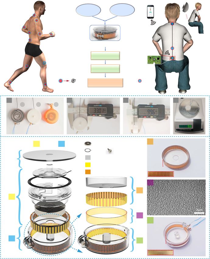
ARTICLE NATURE COMMUNICATIONS | https://doi.org/10.1038/s41467-021-23207-8
H
uman motions, such as bending and stretching, with extends or contracts, as the human subject bends or strengthens.
various amplitudes and velocities ranging from slight The as-generated electrical signals from TENG are obtained,
movement to full-body kinematics, contain diverse and processed, and then transmitted via Bluetooth to the monitoring
important physiological health information1,2, and this physio- terminal, e.g., a cell phone.
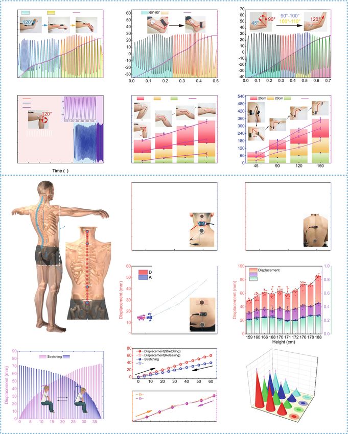
logical health information is often closely or potentially related to Figure 1bi shows the image of three fabricated devices,
diseases, for example, the freezing of gait, a paroxysmal block of encapsulated with various three-dimensional (3D) printing boxes.
movement, often takes place in the advanced stage of Parkinson’s The overall device takes a diameter of 33 mm, a thickness of 10
disease3,4; muscle aches and weakness in limbs, leading to mm, and a weight of 9.6 g (Fig. 1bii–iv). Due to the small volume
movement disorders, might suggest early rheumatism5,6. Addi- and lightweight, it is able to be taped on the skin, or mounted in
tionally, office people now sit for long periods of time everyday7. some vests.
Maintaining such one single posture for a long time might Figure 1c shows an exploded view of the device. The
probably lead to disorders in the spine8, as well as fatigue for their construction involves (1) the lid, (2) the rotor, and (3) the stator,
body, regarded as the major factors resulting in a significant coaxially assembled. The rotor is mainly made up of a coil spring
increase in the risk of back pain9,10. According to recent resear- (see Supplementary Fig. 2 for the elastic coefficient curves of three
ches, over 60% of Americans and 50% of Europeans are about to different coil springs) and a group of grating electrodes (Cu, ~35-
experience back and neck pain at some point in their lives11,12. μm thick; height, 5 mm; width, 0.5 mm; spacing, 0.1 mm), while
Worse, that time tends to come in advance. the stator includes two groups of complementary grating
Traditional cameras13 and inertial measurement units14 electrodes (Cu, ~35-μm thick; spacing, 0.1 mm), covered by
(IMUs) can be used for monitoring human motions and postures Kapton (~35-μm thick), with its surface ion-etched in order to
potentially15. However, the former is not a wearable technique. enhance the output performance (Fig. 1cii). The grating
When the subject moves from one place to another, out of the electrodes on the rotor and stator, and the Kapton film, compose
camera’s view, the monitoring will be interrupted. In addition, the into a freestanding TENG. A screw is used to adjust the gap
IMUs are mainly based on point measurement, requiring com- between the rotor and stator, which can thereby adjust the
plicated body parameters for post-computational modeling to sensor’s output performance. A detailed description of the overall
calculate out the motions, which is indirect. As we know, during fabrication procedure is available in Supplementary Fig. 1 and
the inertial measurement, misalignment error grows as a function Methods.
of time, which will reduce the sensing system’s precision, and
thus extra correction is required from time to time. Therefore,
direct, conformal, and wearable sensing techniques are in Working principle and electrical characteristics. Figure 2a dis-
demand. Recent advances in soft electronics put forward flexible plays the top view of the rotor electrodes rotating clockwise
and stretchable functional sensors16–18, mainly based on relative to the stator electrodes, where the left and middle images
piezoresistive19, capacitive20, and piezoelectric architectures21. show respectively the state when the rotor’s electrodes coincide
They are continuous and conformal on human bodies, exhibiting with the electrodes A or B on the stator (more detail for
high stretchability and high performance22–24. However, as for the working mechanism of the sensor, see Supplementary Fig. 3).
the soft piezoresistive and capacitive devices, challenges, resulting The right image shows the rotor and stator’s 3D structural
from materials17,20,22, still remain, such as hysteresis, robustness, schematics, from which we can see the complementary grating
and environmental interferences, whereas, devices with rigid parts electrodes A and B located on the stator, and the freestanding
and soft connections might suffer from nonlinearity. The newly electrodes located on the rotor. Via the electrode hole on the
developed triboelectric nanogenerator (TENG)25 combines flex- backside, electrodes A and B can be connected with the external
ible materials/substrates that make the overall device wearable, measurement circuit.
with sophisticated circuit fabrication engineering26 that ensures Figure 2b shows the working mechanism of the stretch sensor
the device work stable, and demonstrates its advances in either based on the triboelectric nanogenerator (TENG). During
kinetic energy converting27 or self-powered motion sensing28. rotating, the freestanding electrodes rub with the Kapton film,
Here, we describe a badge-reel-like stretch sensor, based on a inducing electrification31,32. Due to the charge-transferring law,
grating-structured triboelectric nanogenerator (TENG)29,30. It the charge density on the rotor electrode is about two times that
stretches and contracts, synchronously with human subject on the Kapton. In the initial state (the rotor electrodes align with
bending and stretching, exhibiting a high sensitivity of 8 V mm−1, electrode A on the stator), induced charges accumulate on
a minimum resolution of 0.6 mm, excellent robustness (over 120- electrodes A and B with the same charge amount but opposite
thousand stretching cycles), and a low hysteresis. We used it to polarity. As the rotor slides, free electrons keep flowing from
record joint motions, such as knee/arm bending, neck/waist electrode A to electrode B via the external circuit, until the rotor
twisting, demonstrating its functionality for real-time monitoring. reaches the final state where the charge on both electrodes is the
Furthermore, we attached it along the spine, including S1–L1, L1/ same in amount but reversed in polarity. The electron flow is
T12–C7, C1–C7, and S1–C7 (C, T, L, and S represent the cervical, driven by electrostatic force in order to reach an electrostatic
thoracic, lumbar, and sacrum segments of the spine, respectively, equilibrium. As the rotor keeps sliding, the electrons will
and the numbers stand for the corresponding stacked bones), to periodically flow forth and back (the working principle of reverse
detect the spinal shape change, presenting its potential application rotation is shown in Supplementary Fig. 5a).
in daily spinal monitoring. Figure 2c illustrates the finite element analysis (FEA, by
COMSOL Multiphysics) results of the open-circuit potential
distribution on electrodes A and B during rotation with the
Results electrode width of 0.3 mm. Figure 2d plots out the voltage
Device and structural design. By combining a retractable badge between the electrodes A and B (with various electrode widths),
reel and the grating-structured triboelectric nanogenerator as the rotor slides. It exhibits a periodic voltage waveform. As the
(TENG), a small-volume and high-precision stretch sensor has electrode width increases, the peak-to-peak value rises. More FEA
been developed for wearable and real-time monitoring human results can be found in Supplementary Fig. 5 and Supplementary
motions (Fig. 1a). The sensor retains a simple operation principle Movie 1. In theory, the variation trend of the Voc can be
of a retractable reel: with two ends placed on the subject body, it approximately expressed as follows (detailed derivation is
2 NATURE COMMUNICATIONS | (2021)12:2950 | https://doi.org/10.1038/s41467-021-23207-8 | www.nature.com/naturecommunications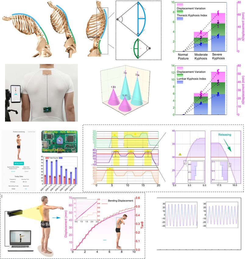
NATURE COMMUNICATIONS | https://doi.org/10.1038/s41467-021-23207-8                                                                           ARTICLE

Fig. 1 Concept illustrations, schematic diagrams, photographs, and exploded view of the stretch sensor. a Illustration of the thin, lightweight, and
wearable stretch sensor placed around the full body to monitor the joint and spinal motions, with continuous, wireless monitoring ability. b Images from a
top view showing (i) the representative stretch sensors made up of two different 3D printing materials, i.e., photosensitive resin (1) and white resin material
(2), and (3) displays a commercial retractable badge reel. In addition, the diameter (ii) and height (iii) of the sensor are shown. c Exploded view of the
stretch sensor, consisting of (1) lid, (2) rotor, and (3) stator, and enlarged images: (i) the rotor electrode, (ii) etched nanorods on the surface of Kapton
film, and (iii) the stator electrode.

available in Supplementary Note 1):                                              freestanding electrode. The equation shows that when the
                                                                               electrode width L1 increases, the voltage will rise, consistent with
                          dσ     L x      x
               V OC ðxÞ ¼        1                                      ð1Þ    the FEA simulations. It is also worth noting that (Fig. 2d), when
                          ε0 εr     x    L1  x                                  the rotor slides over a distance of L1 + L2, Voc reverses,
where L1 represents the electrode width, L2 the electrode gap                    shifting from the peak to the valley, or the valley to the
(considering that the value of L2 is negligible compared to that of              peak, meaning a half-period. Therefore, the overall displacement
L1, L2 can be ignored), d the dielectric material’s thickness, σ the             can be figured out by counting the number of half a period N,
tribocharge density, ε0 vacuum permittivity, εr the dielectric                   and L1 + L2 stands for the minimum resolution. In addition,
material’s relative permittivity, x the displacement of the                      the voltage signal’s frequency can be expressed as the

NATURE COMMUNICATIONS | (2021)12:2950 | https://doi.org/10.1038/s41467-021-23207-8 | www.nature.com/naturecommunications                                     3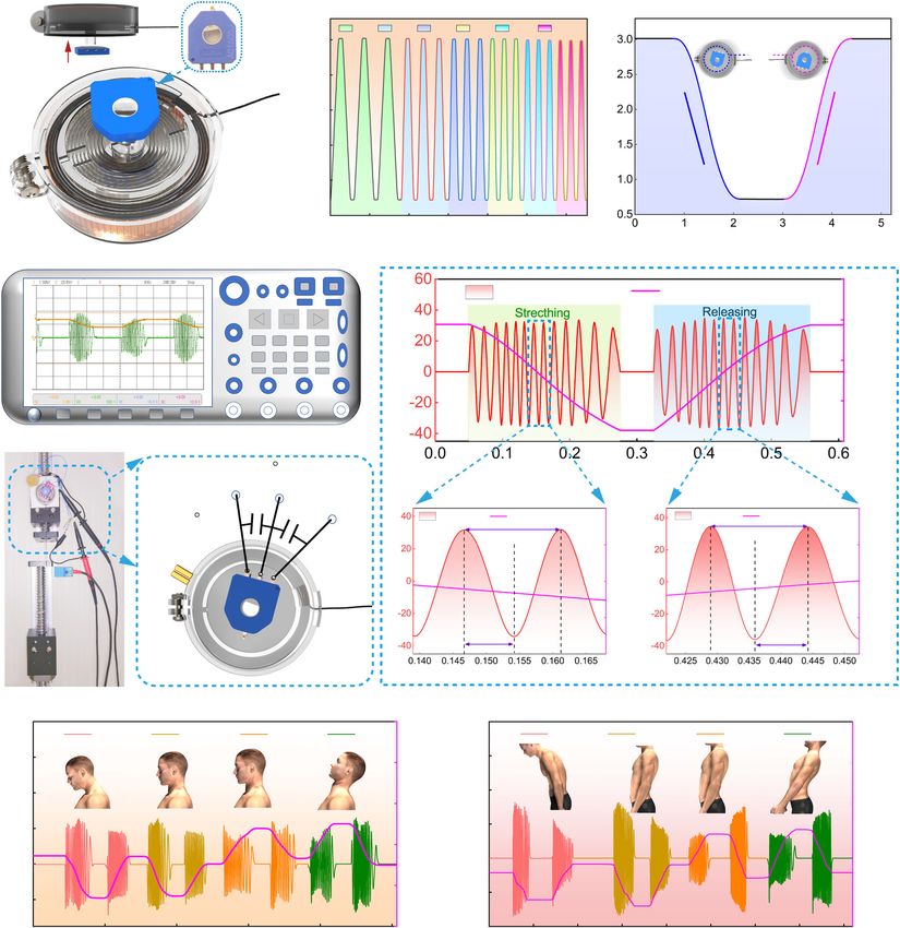
ARTICLE                                                                    NATURE COMMUNICATIONS | https://doi.org/10.1038/s41467-021-23207-8

Fig. 2 The working principle, output performance, and characteristics of temperature and humidity of the device. a A top view of the stretch sensor
when rotating clockwise and anticlockwise, and the right side of the image indicates the detail of the device’s 3D structure. b Schematic diagram of the
working mechanism of the stretch sensor based on freestanding triboelectric nanogenerators (TENG). c Potential simulation of one working cycle by FEA
with 0.3-mm electrode width, and (d) the simulated results of the open-circuit voltage with different electrode widths 0.3, 0.5, 0.7, and 0.9 mm. e The
basic electrical output characteristic diagram of the stretch sensor with 0.5-mm electrode widths. f Voltage signals with different velocities from 50 to 250
mm s−1 under a given displacement (36 mm) and g represents the theoretical and measured frequency corresponding to different velocities. h–i The
output performance of the sensor at different environmental temperatures and humidity, and its corresponding displacement accuracy is shown in j. All
error bars represent standard deviation based on ten replicate data under the same test condition. Source data are provided as a Source Data file.

following formula:                                                              freestanding electrode). Subsequently, we used an oscilloscope
                                        v                                       (DSO2014A Keysight, USA) to examine the sensor’s perfor-
                             f ¼                                         ð2Þ    mance. Figure 2e displays an output of a device with its electrode
                                   2ðL1 þ L2 Þ                                  width of 0.5 mm (more details are available in Supplementary
where v represents the sliding velocity of the rotor (the                       Movie 2). It exhibits a periodic waveform, with a peak-to-peak

4                  NATURE COMMUNICATIONS | (2021)12:2950 | https://doi.org/10.1038/s41467-021-23207-8 | www.nature.com/naturecommunications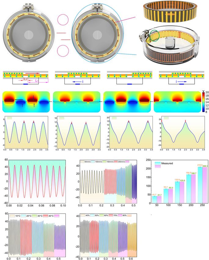
NATURE COMMUNICATIONS | https://doi.org/10.1038/s41467-021-23207-8                                                                    ARTICLE

value ~80 V. As the sliding velocity increases, the output                      test as an example (Fig. 3h), the subject made a nod with mild/
frequency becomes higher, as well as the output current, due to                 moderate/severe amplitude, the inclinometer gave outputs ~10, 20,
that with a given transferred charge amount, the velocity rises, the            and 30°, whereas, the stretch sensor delivered average displacements
transferring time shortens (Fig. 2f). It is worth noting that we                about 13, 27 , and 38 mm, presenting an excellent correlation. Tests
employed the oscilloscope, which is equivalent to a 100-MΩ                      on thoracic and lumbar vertebra can be found in Fig. 3i, j.
resistor, to measure the voltage, and thus, the voltage value                   Simultaneously, the experimental results in different application
increases as the current increases. Subsequently, as a comparison,              scenes (experiment workbench/human body) and under various
we plot the measured frequency and theoretical value (calculated                human postures (standing/sitting) are shown in Supplementary
by Eq. (2)) in Fig. 2g, which are consistent well, indicating a high            Fig. 7, which further demonstrates the stability of the stretch sensor.
fabrication precision. For more output performance tests of                        Moreover, we performed tests on different persons. Ten
electrodes with different electrode widths, see Supplementary                   volunteer participants (age 21–40 years of old; stature 159–188
Fig. 6.                                                                         cm; BMI 19.5–24.5) were recruited to participate in the study.
   Moreover, as a wearable sensor, the electrical output of the                 The selection was based on the nonobese range of body mass
device might be inevitable to be affected by environmental                      index (BMI). We adhered to the two ends of the sensor at the
temperature and humidity. We studied this and plot results in                   positions of S1 and C7. Predictably, the displacement increased
Fig. 2h, i. It is found that the output voltage will decrease slightly          with the subject’s height (Fig. 3k). However, some exceptions
as the temperature rises (Fig. 2h). And the increase of humidity                occur, e.g., the 171-cm-high participant. We normalized the
has a bare significant effect on the performance, due to the                     displacement by dividing it by the participant height, and plot it
protection of the encapsulation (Fig. 2i). However, the displace-               as the purple line. The normalized displacement shows that the
ment achieved by our device is determined by the half-period                    value of the 171-cm-high participant is still smaller. We speculate
number N and the structural length L1 + L2, as discussed above.                 that the smaller movement might be attributed to the Kyphosis
This approach apparently avoids the output value variation owing                appearance on the participant’s back; thus, the initial curvature
to the environmental interferences. As we can see in Fig. 2j, for               on the spine results in smaller bending amplitude. In addition,
displacements of 20, 40, and 60 mm, under different temperatures                participants’ bending angles are plotted as the green part, which is
and humidity, the sensor delivers precise displacement measures.                consistent with the normalized displacement data.
                                                                                   Subsequently, the device’s hysteresis is investigated and
                                                                                presented in Fig. 3l, m. As shown in the upper image of Fig. 3m,
Full-body bending monitoring by the stretch sensor.                             with the linear motor stretching, the device delivered precisely the
Figure 3a–f shows the application of using the stretch sensor to                stretching displacement (red dots), whereas, when the linear
monitor motions of the human wrist, ankle, elbow, knee, and                     motor moves backward, the device also delivered precise releasing
shoulder. As shown in Fig. 3a, the stretch sensor is fixed between               displacement (red pentacles). In addition, we did the verification
the forearm and the hand, across the wrist, to record the voltage               as a function of the inclination angle (the lower image in Fig. 3m).
response under the wrist’s stretching/releasing. With the wrist                 It shows that the stretching displacement (orange circles) and
bending from 120° to 225°, the sensor outputs continuous voltage                releasing displacement (purple dots) coincide well. The misalign-
signals, measured by the oscilloscope. The peak value is ~20–30 V,              ment should be due to that the subject could not ensure a perfect
determined by the bending speed33, while the stretching dis-                    same bending angle during stretching and releasing. Overall, our
placement increased step by step, with one step meaning 0.6 mm.                 device exhibits an ultralow hysteresis.
Similarly, bending motions of the ankle (Fig. 3b) and the elbow                    Figure 3n shows that under a same bending on the spine, when
(Fig. 3c and Supplementary Movie 3) can also be measured.                       the two ends of the stretch sensor are placed on S1 and C7, the
Furthermore, as shown in Fig. 3d, the sensor is fixed between the                displacement changes largest, followed by that of sensors on
thigh and the calf, and we examined the sensor performance                      L1–C7, S1–L1, and C1–C7. It indicates that the stretch sensor
under a fixed angle and various bending speeds (for more details,                needs to be placed in the proper position to achieve a large value
see Supplementary Movie 3). It is indicated that high speed will                under a fixed bending angle.
lead to high voltage and frequency, but the same peak number and
displacement value. In addition, Fig. 3e suggests excellent linearity
between the displacement and the bending angle. Afterward, we                   Constructing a vector stretch sensor. To form a complete
placed the sensor in different positions on the thigh, resulting in             monitoring system, we integrated a potentiometer with high
different initial lengths. The measured results show that the farther           linearity (±0.2) and ultrahigh durability (1 M cycles) into the
the sensor is away from the joint rotation point, the larger the                above device to construct a vector stretch sensor (the details of
displacement is, as well as the peak number. Similar results can be             potentiometer performances and its various electrical parameter
found in the test on the shoulder (Fig. 3f).                                    information are available in Supplementary Fig. 8 and Supple-
   Current clinical investigations into the spine are lacking of                mentary Table 1). As shown in Fig. 4a, the potentiometer is
wearable and real-time technologies and mainly based on X-ray                   coaxially placed right above the TENG device. A tiny stainless
film, which is time-consuming and harmful. IMU technique could                   shaft is employed to connect the TENG to the potentiometer,
be applied, however, it requires complicated body parameters to                 making two components rotate simultaneously. After applying a
build the individual body model, and the measuring is indirect34–37.            DC voltage source of 3 V, we measured the voltage of the
As our proposed stretch sensor is thin and attachable, we utilized it           potentiometer under different stretching speeds with a same
to qualitatively analyze the displacement change of the spine during            displacement (60 mm) (Fig. 4b). Figure 4c illustrates the poten-
bending or stretching, by fixing it at the positions along the spinous           tiometer’s voltage curve under stretching, i.e., anticlockwise
process joints, including cervical, thoracic, and lumbar spine                  rotating, and releasing, i.e., clockwise rotating, with a rotating
(Fig. 3g) in the sagittal plane. In addition, an inclinometer based             speed of 60 mm s−1.
on acceleration sensing (Supplementary Fig. 12) is also employed as                Afterward, the vector stretch sensor composed of a TENG
a comparison. Testing results are shown in Fig. 3h–n. The stretch               device and potentiometer was examined. Figure 4d shows the
sensor is fixed respectively along the spine on points of C1 and C7              measurement configuration, with a two-channel oscilloscope and
(Fig. 3h), L1 and C7 (Fig. 3i), and S1–L1 (Fig. 3j). The inclinometer           a linear motor. Two capacitors C1 (100 nF) are added to the two
is placed right in the middle position. Taking the cervical vertebra            ends of the potentiometer for filtering. Outputs are

NATURE COMMUNICATIONS | (2021)12:2950 | https://doi.org/10.1038/s41467-021-23207-8 | www.nature.com/naturecommunications                             5
ARTICLE NATURE COMMUNICATIONS | https://doi.org/10.1038/s41467-021-23207-8 simultaneously recorded by the two channels of an oscilloscope between one signal peak and one signal valley, equal to L1 + L2, as (Fig. 4e). Besides the continuous oscillation signal, a gradually discussed above. Subsequently, we fixed the sensor on the increasing/decreasing voltage was obtained, from the potenti- participants’ cervical spinous process C1–C7, and thoracic ometer, exactly related to the stretching/releasing direction spinous process L1–C7, monitoring the signal outputs when they (Supplementary Movie 2). Additionally, we illustrate the mini- do some setting-up exercises (Fig. 4f, g) (the test of arm and leg mum displacement, able to be measured by the stretch sensor, in movement, please see Supplementary Fig. 9). Taking the cervical the lower image of Fig. 4e, which is determined by the distance exercise (Fig. 4f) as an example, “1” represents lowering the head, 6 NATURE COMMUNICATIONS | (2021)12:2950 | https://doi.org/10.1038/s41467-021-23207-8 | www.nature.com/naturecommunications
NATURE COMMUNICATIONS | https://doi.org/10.1038/s41467-021-23207-8                                                                        ARTICLE

Fig. 3 Detection of multijoint movements and spinal bending using the stretch sensor. a–c The measurement of dynamic wrist/ankle/elbow bending via
the stretch sensor attached on the body, respectively. d The voltage output signal of knee bending at different speeds. e, f Comparisons of knee/shoulder’s
angle variation with the stretching displacement. g Schematic illustration of a human spine model with devices’ potential fixed positions marked with blue
dots. h–j Detection of stretching displacement of cervical segment C1–C7, thoracic segment L1–C7, and lumbar segment S1–L1 at different bending degrees
included mild curvature, moderate curvature, and severe curvature. The photographs of the device mounting on the human body are also inserted. k The
relationship between the bending angle and the displacement (unnormalized and normalized) measured by the stretch sensor. l The relationship between
the bending angle and the displacement when bending up and down (the sensor is fixed on spinal process S1–C7 and the volunteer is 178-cm high). m The
hysteresis characteristics of the stretch sensor measured by a linear motor (the image above) and a volunteer (the image below) respectively, showing
almost no hysteresis in a cycle of stretching and releasing. n The stretch sensor was fixed to different locations of spinous processes (C1–C7, L1–C7, S1–L1,
and S1–C7), showing different displacement variations. All error bars represent standard deviation based on ten replicate data, including displacement,
angle, and the number of peaks. Source data are provided as a Source Data file.

“e” represents returning back, “&” and “a” means repeating the                  precisely. A demonstration of the posture monitoring system
above process of “1” and “e”, respectively. “2” means the                       connected to an APP on a mobile phone can be found in
participant leans back the head, “e” returning back, and “&”                    Supplementary Movie 5.
and “a” means repeating the above process of “2” and “e”,                           Simultaneously, we utilized a commercial depth camera
respectively. In addition, the monitoring of thoracic exercises is              (Kinect 2.0, see Supplementary Fig. 12) to capture a participant’s
plotted out in Fig. 4g. These tests show the vector stretch sensor              real-time bending motions and made a comparison with the
able to serve as a wearable device for posture monitoring, physical             stretch sensor. The parameter tanθ = A/B (Fig. 5i, j) is chosen as
rehabilitation training, and so on.                                             the bending amplitude, where A, B is obtained through the
                                                                                customized skeleton tracking program using the Microsoft
Spinal and posture monitoring system. Using the stretch sensor                  Software Development Kit (SDK, Redmond, Washington, USA,
for real-time monitoring, our spinal motions represent a potential              see Supplementary Fig. 13). As the human subject bends, the
application that may reduce the cervical, vertebra, and back pain               parameter value increased step by step, under a sampling rate of
diseases in clinical, or decrease the number of hunchbacks. Fig-                10 Hz. In comparison, the stretch sensor output is plotted in red,
ure 5a shows the definition of the kyphosis index (KI), where L                  exhibiting a superior continuity and precision (Fig. 5j).
represents the distance between C7 and T12, H the height of the                     Moreover, we measured the robustness of the sensor. The results
curve, F the distance between T12 and L1, E the height. Therefore,              indicate that the sensor can maintain stable electrical output
the thoracic kyphosis index (TKI) can be expressed as TKI = H/L                 performance after 120,000 continuous working cycles, under a
× 100, and the lumbar kyphosis index (LKI) as LKI = E/F × 100.                  given displacement of 50 mm (Fig. 5k and Supplementary Movie 6).
The thoracic/lumbar kyphosis angle (KA) can be respectively                     It is worth noting that, the triboelectric layer still works. Instead, the
calculated according to the following formulas38,39: α = 4 arctan               3D printing encapsulation box is deformed, leading to the sensor
2H/L as well as α = 4 arctan 2E/F.                                              layoff (more details can be found in Supplementary Fig. 14).
   Figure 5b, c shows a participant’s (height = 1.75 m, weight = 70 kg,
BMI ≈ 23) testing results, on the thoracic and lumbar vertebra,                 Discussion
respectively. The TKI and KA were assessed and calculated through a             In summary, we presented a precise, durable, and wearable stretch
traditional Flexicurve ruler (see Measurement methods: measurement              sensor based on triboelectric nanogenerator, and demonstrated its
of kyphosis index and kyphosis angle). Meanwhile, the stretch                   capability of sensing human’s joint motions and monitoring the
sensor recorded the stretching displacement. The results exhibit that           real-time spinal bending/stretching in a sagittal plane. The test
the displacement increase is linearly related to the variation of the           compared with the commercial inclinometer and depth camera
TKI, as the participant bends from the normal posture to the severe             demonstrates the feasibility and accuracy of our sensor for
kyphosis.                                                                       recording spinal motions. Experiments on over tens of participants
   As shown in Fig. 5d, we can define another parameter that is                  and full-body joints confirm its ubiquity. In addition, we developed
obtained by using the displacement dividing the kyphosis angle.                 the vector stretch sensor and a spinal monitoring system, which is
The larger parameter value means under a fixed kyphosis angle                    capable of real-time monitoring the subjects’ spinal motions, and
variation, the displacement is larger, suggesting where our stretch             sending out reminding wirelessly according to customized settings.
sensor should be placed. Subsequently, in order to facilitate                   Key advances involve (1) the capabilities in wearablely, conformally
wearable and movable applications, the vector stretch sensor has                and real-time wireless monitoring human’s bending/stretching
been embedded into a circuit (size 4 × 6.5 cm, the detailed circuit             motions, (2) the grating-structured TENG and the peak-number-
diagram is available in Supplementary Fig. 10). Data are                        counting technique providing high precision, high repeatability, low
processed and then transmitted via Bluetooth to be displayed in                 hysteresis, and high robustness to environmental interferences, and
an APP on a mobile phone, including intraday data and weekly                    (3) the sophisticated and scalable engineering fabrication process
summary on the spinal motion (Fig. 5f–h and Supplementary                       making the device high yield, uniform, and durable.
Movie 4). In order to verify the feasibility of the sensor system, we              Notably, our proposed vector stretch sensor is capable of being
connected it to the computer through a serial port and demoed a                 mounted into the vest/kneepad for personal daily wears. How-
spine motion alarm system (see Supplementary Fig. 11). Accord-                  ever, the weak adhesion between the wears and the human skin
ing to the above analysis (Fig. 5d), we fix the sensing system                   will lead to sliding of the sensor, inducing some noise and
between L1 and C7 on the thoracic spine of the participant. The                 decrease to the sensing signals. To avoid this problem, wears
results are shown in Fig. 5i. We set the alarm threshold value to               could be attached to the human skin with the aid of intermedia
20, 30, and 40 mm, and the number of alarms is recorded as 2, 3,                adhesive layer40, ensuring simultaneous and conformal bending
and 1 times, respectively, when the human subject completed a                   and stretching. In addition, the device also works well for real-
series of similar actions. Moreover, the enlarged images on the                 time monitoring of the spine and ankle motions (Supplementary
right of Fig. 5i show detailed signals during stretching and                    Movie 7), but one more support point in the bending spot is
releasing. Each step on the stretching/releasing curve is 0.6 mm                required in order to hide the out-of-plane line. Moreover, the

NATURE COMMUNICATIONS | (2021)12:2950 | https://doi.org/10.1038/s41467-021-23207-8 | www.nature.com/naturecommunications                                  7
ARTICLE NATURE COMMUNICATIONS | https://doi.org/10.1038/s41467-021-23207-8 Fig. 4 Schematic diagram and electrical characteristics of the vector stretch sensor. a 3D structure diagram of the vector stretch sensor. b The voltage output performance of the potentiometer at different stretching speeds under the same stretching displacement (60 mm), c Potentiometer’s output voltage curve under stretching, i.e., anticlockwise rotating, and releasing, i.e., clockwise rotating, with a rotating speed of 60 mm s−1. d Measurement circuit. e The measured output of the TENG device and potentiometer under stretching and releasing, the two enlarged images below indicate the displacement calculation. f, g Monitoring the signal outputs via the vector stretch sensor when the participant does some exercises, including neck/ thoracic exercise gymnastics. Source data are provided as a Source Data file. sensing part is based on the triboelectric nanogenerator that in the office. In addition, it can serve as a rehabilitation brace for works actively with the self-powered ability, compared to piezo- real-time recording of patients’ joint motions during the long resistive or capacitive sensing devices. Generally, the stretch recovering time after injuries. As the demand for personal sensor shows outstanding durability compared with other healthcare monitoring and wearable sensing technologies is stretchable sensors in the literature17,41, and the manufacturing increasing, these precise, mass-production, wearable, and durable procedure is batch fabrication, making it feasible, cost-affordable, devices based on the triboelectric nanogenerator will impose a and industry-translatable. disruptive impact on the personal medical sensing field and Overall, our proposed technology could be beneficial to reduce therefore form a starting point for further developments of the risks of spinal disorders, especially for those long-term sitting advanced wearable sensing devices. 8 NATURE COMMUNICATIONS | (2021)12:2950 | https://doi.org/10.1038/s41467-021-23207-8 | www.nature.com/naturecommunications
NATURE COMMUNICATIONS | https://doi.org/10.1038/s41467-021-23207-8                                                                       ARTICLE

Fig. 5 Spinal measurement and posture monitoring. a Three different posture states of normal posture, moderate kyphosis, and severe kyphosis,
respectively, the right of the image shows the calculation method of thoracic kyphosis index (TKI) and lumbar spine kyphosis index (LKI), that is TKI = H/L
× 100, and LKI = E/F × 100. b, c Indicating the changes of the thoracic/lumbar kyphosis indexes under the above-mentioned three posture states as well as
the changes of thoracic/lumbar kyphosis angle and corresponding displacement. d The ratio of the displacement divided by the kyphosis angle to
determine the fixed position of the stretch sensor. e Demonstration of applying the sensor system to recoding the vector displacement caused by spinal
bending, and (g) displays the image of the integrated circuit board. f–h Mobile phone APP interface (mobile terminal) representing intraday data and
weekly historical information, respectively. i Schematic diagram of the verification results of the sensor system feasibility analysis, and the two enlarged
images represent the detailed signals of stretching and releasing, showing the gradient accuracy of +0.6 mm and −0.6 mm, respectively. j Synchronous
continuous measurement of volunteers’ inclination angle from spine base to neck using commercial depth cameras and stretch sensor. k The stability and
life testing of the stretch sensor. All error bars denote standard deviation based on ten replicate data under the same test condition. Source data are
provided as a Source Data file.

NATURE COMMUNICATIONS | (2021)12:2950 | https://doi.org/10.1038/s41467-021-23207-8 | www.nature.com/naturecommunications                                 9
ARTICLE                                                                               NATURE COMMUNICATIONS | https://doi.org/10.1038/s41467-021-23207-8

Methods                                                                                    8.    Lis, A. M., Black, K. M., Korn, H. & Nordin, M. Association between sitting
Sensor fabrication. The fabrication of the sensor is mainly based on the mature                  and occupational LBP. Eur. Spine J. 16, 283–298 (2007).
technology of 3D printing and flex printed circuit board (FPCB) technology. The             9.    Bootsman, R., Markopoulos, P., Qi, Q., Wang, Q. & Timmermans, A. A. A.
sensor has been made through 3D printing equipment (Object30 Prime, Stratasys,                   Wearable technology for posture monitoring at the workplace. Int. J. Hum.
USA) to print out the sensor components, and prepare other assembly materials,                   Comput. Stud. 132, 99–111 (2019).
such as coil springs, ropes, screws, nuts, and custom double-sided tape to assemble        10.   Poitras, S., Blais, R., Swaine, B. & Rossignol, M. Management of work-related
(the detail fabrication information is available in Supplementary Fig. 1).                       low back pain: a population-based survey of physical therapists. Phys. Ther.
                                                                                                 85, 1168–1181 (2005).
Fabrication of the Flex PCB. We used the electronic structural design software             11.   Alexander, E. P. History, physical examination, and differential diagnosis of
called Altium Designer 20 to draw the FPCB structural sketches and make pro-                     neck pain. Phys. Med. Rehabil. Clin. N. Am. 22, 383–393 (2011).
duction. The optical photograph of the FPCB is shown in Supplementary Fig. 5.              12.   Hoy, D. et al. The global burden of low back pain: estimates from the Global
Detailed fabrication procedures are revealed as follows: the pr-cleaned substrate                Burden of Disease 2010 study. Ann. Rheum. Dis. 73, 968 (2014).
chosen for both the rotator and stator is Polyimide (PI) with a thickness of 0.095         13.   Mateo, F. et al. HemoKinect: a microsoft kinect V2 based exergaming software
mm, subsequently, when the copper-clad substrate sheets are ready, which the                     to supervise physical exercise of patients with hemophilia. Sensors 18, 2439
plating thickness of copper is 0.035 mm, and then the pattern will be transferred to             (2018).
the substrate followed by laminate a sensitive dry layer on the top of the copper          14.   Robert-Lachaine, X., Mecheri, H., Larue, C. & Plamondon, A. Validation of
sheet, after that, the sensitive layer is exposed to patterned UV lamps via photo                inertial measurement units with an optoelectronic system for whole-body
tools, and the nonexposure areas can be removed to reveal the copper underneath                  motion analysis. Med. Biol. Eng. Comput. 55, 609–619 (2017).
through the etching process, leaving the patterns intact. After the etching is done        15.   Lee, K. et al. Mechano-acoustic sensing of physiological processes and body
and unwanted copper removed, and the surface finish is applied to protect the                     motions via a soft wireless device placed at the suprasternal notch. Nat.
circuit.                                                                                         Biomed. Eng. 4, 148–158 (2020).
                                                                                           16.   Yamada, T. et al. A stretchable carbon nanotube strain sensor for human-
Electrical measurements and materials characterization. All measurements of                      motion detection. Nat. Nanotechnol. 6, 296–301 (2011).
the stretch sensor were performed using a Keysight (Type: DSO2014A) oscillo-               17.   Ray, T. R. et al. Bio-integrated wearable systems: a comprehensive review.
scope, and the output voltage was supplied by an SRS (Stanford Research Systems)                 Chem. Rev. 119, 5461–5533 (2019).
DS345 function generator.                                                                  18.   Son, D. et al. An integrated self-healable electronic skin system fabricated via
                                                                                                 dynamic reconstruction of a nanostructured conducting network. Nat.
                                                                                                 Nanotechnol. 13, 1057–1065 (2018).
Nanostructure characterization. Field-emission electron microscopy (Hitachi
                                                                                           19.   Lipomi, D. J. et al. Skin-like pressure and strain sensors based on transparent
SU8020) was used to characterize the nanostructures induced by the Kapton film
                                                                                                 elastic films of carbon nanotubes. Nat. Nanotechnol. 6, 788–792 (2011).
membrane surface.
                                                                                           20.   Nur, R. et al. A highly sensitive capacitive-type strain sensor using wrinkled
                                                                                                 ultrathin gold films. Nano Lett. 18, 5610–5617 (2018).
Measurement of human body bending inclination. We used Unreal Four Engine                  21.   Han, M. et al. Three-dimensional piezoelectric polymer microsystems for
developed by Epic Games, the SDK skeleton tracking package was customized by                     vibrational energy harvesting, robotic interfaces and biomedical implants. Nat.
using blueprint and C++ to track and measure the inclination angle of human                      Electron. 2, 26–35 (2019).
body bending in real time (Supplementary Fig. 13).                                         22.   Cho, D. et al. Three-dimensional continuous conductive nanostructure for
                                                                                                 highly sensitive and stretchable strain sensor. ACS Appl. Mater. Interfaces 9,
Measurement of kyphosis index (KI) and kyphosis angle (KA). The Kyphotic                         17369–17378 (2017).
Index (KI) and Kyphosis angle (KA) will be calculated via using an architect’s             23.   Roh, E., Hwang, B. U., Kim, D., Kim, B. Y. & Lee, N. E. Stretchable,
Flexicurve ruler (Supplementary Fig. 12), which was molded onto the spinous                      transparent, ultrasensitive, and patchable strain sensor for human–machine
process of C7 to the interspace of L5–S1. This mold was traced onto paper, and a                 interfaces comprising a nanohybrid of carbon nanotubes and conductive
vertical line was drawn to align the C7 spinous process and the interspace of L5–S1.             elastomers. ACS Nano 9, 6252–6261 (2015).
After that, through drawing a horizontal line connecting the apex and the per-             24.   Han, M. et al. Catheter-integrated soft multilayer electronic arrays for
pendicular to the thorax curve, the KI and corresponding KA will be calculated as a              multiplexed sensing and actuation during cardiac surgery. Nat. Biomed. Eng.
function of the thoracic/lumbar length and thoracic/lumbar width using standar-                  4, 997–1009 (2020).
dized procedures as previously described (width/length × 100).                             25.   Wang, Z. L. On Maxwell’s displacement current for energy and sensors: the
                                                                                                 origin of nanogenerators. Mater. Today 20, 74–82 (2017).
Reporting summary. Further information on research design is available in the Nature       26.   Tang, W., Han, C. B., Zhang, C. & Wang, Z. L. Cover-sheet-based
Research Reporting Summary linked to this article.                                               nanogenerator for charging mobile electronics using low-frequency body
                                                                                                 motion/vibration. Nano Energy 9, 121–127 (2014).
                                                                                           27.   Pu, X. et al. Ultrastretchable, transparent triboelectric nanogenerator as
Data availability                                                                                electronic skin for biomechanical energy harvesting and tactile sensing. Sci.
All data needed to evaluate the conclusions in the paper are present in the paper and/or         Adv. 3, e1700015 (2017).
the Supplementary Information. Additional data related to this paper may be requested      28.   Wang, Z. et al. A self-powered angle sensor at nanoradian-resolution for
from the authors upon reasonable request. Source data are provided with this paper.              robotic arms and personalized medicare. Adv. Mater. 32, 2001466 (2020).
                                                                                           29.   Zhu, G. et al. Linear-grating triboelectric generator based on sliding
                                                                                                 electrification. Nano Lett. 13, 2282–2289 (2013).
Received: 26 November 2020; Accepted: 30 March 2021;
                                                                                           30.   Niu, S. et al. Theory of sliding-mode triboelectric nanogenerators. Adv. Mater.
                                                                                                 25, 6184–6193 (2013).
                                                                                           31.   Han, K. et al. Self-powered electrocatalytic ammonia synthesis directly from
                                                                                                 air as driven by dual triboelectric nanogenerators. Energy Environ. Sci. 13,
                                                                                                 2450–2458 (2020).
                                                                                           32.   Bai, Y. et al. Charge pumping strategy for rotation and sliding type
References                                                                                       triboelectric nanogenerators. Adv. Energy Mater. 10, 2000605 (2020).
1.   Azocar, A. F. et al. Design and clinical implementation of an open-source             33.   Liu, D. et al. A constant current triboelectric nanogenerator arising from
     bionic leg. Nat. Biomed. Eng. 4, 941–953 (2020).                                            electrostatic breakdown. Sci. Adv. 5, eaav6437 (2019).
2.   Seshadri, D. R. et al. Wearable sensors for monitoring the physiological and          34.   Pfister, F. M. J. et al. High-resolution motor state detection in
     biochemical profile of the athlete. npj Digit. Med. 2, 72 (2019).                            Parkinson’s disease using convolutional neural networks. Sci. Rep. 10, 5860
3.   Kalia, L. V. & Lang, A. E. Parkinson’s disease. Lancet 386, 896–912 (2015).                 (2020).
4.   Mirelman, A. et al. Gait impairments in Parkinson’s disease. Lancet Neurol.           35.   Lemay, J. F. et al. Using wearable sensors to characterize gait after spinal cord
     18, 697–708 (2019).                                                                         injury: evaluation of test–retest reliability and construct validity. Spinal Cord.
5.   González-Gay, M. A., Matteson, E. L. & Castañeda, S. Polymyalgia                            https://doi.org/10.1038/s41393-020-00559-4 (2020).
     rheumatica. Lancet 390, 1700–1712 (2017).                                             36.   Kobsar, D. et al. Validity and reliability of wearable inertial sensors in healthy
6.   Lorenzi, P. et al. Smart sensing systems for the detection of human motion                  adult walking: a systematic review and meta-analysis. J. Neuroeng. Rehabil. 17,
     disorders. Procedia Eng. 120, 324–327 (2015).                                               62 (2020).
7.   Breen, P. P., Nisar, A. & Olaighin, G. Evaluation of a single accelerometer           37.   Santaera, G. et al. Low-cost, fast and accurate reconstruction of robotic and
     based biofeedback system for real-time correction of neck posture in computer               human postures via IMU measurements. 2015 IEEE Int. Conf. Robot. Autom.
     users. Conf. Proc. IEEE Eng. Med. Biol. Soc. 2009, 7269–7272 (2009).                        (ICRA) (ed. Okamura, A.) 2728–2735 (IEEE, 2015).

10                    NATURE COMMUNICATIONS | (2021)12:2950 | https://doi.org/10.1038/s41467-021-23207-8 | www.nature.com/naturecommunications
NATURE COMMUNICATIONS | https://doi.org/10.1038/s41467-021-23207-8 ARTICLE
38. Roshani, S., Yousefi, M., Sokhtezari, Z. & Khalil Khodaparast, M. The effect of Additional information
a corrective exercise program on upper crossed syndrome in a blind person. Supplementary information The online version contains supplementary material
Int. J. Rehabil. Res. 6, 148–152 (2019). available at https://doi.org/10.1038/s41467-021-23207-8.
39. Amatachaya, P. et al. Validity and reliability of a thoracic kyphotic assessment
tool measuring distance of the seventh cervical vertebra from the wall. Hong. Correspondence and requests for materials should be addressed to W.T. or Z.L.W.
Kong Physiother. J. 35, 30–36 (2016).
40. Cacucciolo, V. et al. Stretchable pumps for soft machines. Nature 572, Peer review information Nature Communications thanks Yijun Shi, Xuhui Sun and the
516–519 (2019). other anonymous reviewers for their contribution to the peer review of this work.
41. Tan, C. et al. A high performance wearable strain sensor with advanced
thermal management for motion monitoring. Nat. Commun. 11, 3530 (2020). Reprints and permission information is available at http://www.nature.com/reprints
Publisher’s note Springer Nature remains neutral with regard to jurisdictional claims in
Acknowledgements published maps and institutional affiliations.
The research was supported by the National Key R & D Project from the Minister of
Science and Technology (2016YFA0202704), Youth Innovation Promotion Association,
CAS, Beijing Municipal Science & Technology Commission (Z171100000317001,
Open Access This article is licensed under a Creative Commons
Z171100002017017, and Y3993113DF), and National Natural Science Foundation of
Attribution 4.0 International License, which permits use, sharing,
China (Grant Nos. 51605033, 51432005, 5151101243, and 51561145021).
adaptation, distribution and reproduction in any medium or format, as long as you give
appropriate credit to the original author(s) and the source, provide a link to the Creative
Author contributions Commons license, and indicate if changes were made. The images or other third party
C.L., W.T., and Z.L.W. conceived the idea and designed the experiment. C.L., D.L., C.Q.X., material in this article are included in the article’s Creative Commons license, unless
and S.S. performed electrical measurement and Supplementary Movies. C.L. and D.L. indicated otherwise in a credit line to the material. If material is not included in the
fabricated the sensors and prepared the figures. Z.M.W. and S.S. helped with the article’s Creative Commons license and your intended use is not permitted by statutory
COMSOL simulations. D.L., Z.R.S., W.T., and Z.L.W. provided assistance with the regulation or exceeds the permitted use, you will need to obtain permission directly from
experiments. C.L., D.L., W.T., and Z.L.W. wrote the paper. All the authors discussed the the copyright holder. To view a copy of this license, visit http://creativecommons.org/
results and commented on the paper. licenses/by/4.0/.
Competing interests © The Author(s) 2021
The authors declare no competing interests.
NATURE COMMUNICATIONS | (2021)12:2950 | https://doi.org/10.1038/s41467-021-23207-8 | www.nature.com/naturecommunications 11You can also read