Engineering Graphics Essentials with AutoCAD 2022 Instruction - Text and Video Instruction
←
→
Page content transcription
If your browser does not render page correctly, please read the page content below
Kirstie Plantenberg

Engineering Graphics Essentials
with AutoCAD 2022 Instruction
                                              ®

Text and Video Instruction

SDC
P U B L I C AT I O N S
                         Better Textbooks. Lower Prices.
                         www.SDCpublications.com
                                                               ACCESS CODE
                                                              UNIQUE CODE INSIDE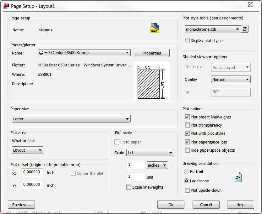
Visit the following websites to learn more about this book:

Powered by TCPDF (www.tcpdf.org)
[ Chapter 4: Creating Orthographic Projections in AutoCAD® ]

                                                                                                                        CHAPTER 4
                  CREATING ORTHOGRAPHIC PROJECTIONS
                                        IN AUTOCAD®

CHAPTER OUTLINE

4.1) INTRODUCTION ...................................................................................................................... 2
4.2) LAYERS ................................................................................................................................... 2
    4.2.1) The Layers panel ..............................................................................................................................5
    4.2.2) Layer properties ................................................................................................................................7
4.3) LINE TYPE SCALE ................................................................................................................ 10
4.4) PROPERTIES ......................................................................................................................... 10
    4.4.1) The Properties panel....................................................................................................................... 11
4.5) PRINTING USING PEN WIDTHS ........................................................................................... 12
4.6) CREATING LAYERS TUTORIAL .......................................................................................... 13
    4.6.1) Setting drawing parameters ............................................................................................................ 13
    4.6.2) Creating layers ................................................................................................................................ 13
    4.6.3) Drawing on different layers ............................................................................................................. 15
    4.6.4) Line type scale ................................................................................................................................ 16
4.7) BLOCKING ............................................................................................................................. 17
4.8) MODEL AND LAYOUT SPACE ............................................................................................. 21
    4.8.1) Model space.................................................................................................................................... 21
    4.8.2) Layout space................................................................................................................................... 21
4.9) CENTERLINES....................................................................................................................... 23
4.10) TITLE BLOCK TUTORIAL ................................................................................................... 25
    4.10.1) Blocking a title block ..................................................................................................................... 25
    4.10.2) Blocking a metric title block ........................................................................................................... 27
4.11) ORTHOGRAPHIC PROJECTION TUTORIAL .................................................................... 30
    4.11.1) Draw the front view ....................................................................................................................... 30
    4.11.2) Drawing the right side view ........................................................................................................... 31
    4.11.3) Drawing the top view..................................................................................................................... 35
    4.11.4) Drawing centerlines ...................................................................................................................... 37
    4.11.5) Printing the layout ......................................................................................................................... 39
    4.11.6) Printing a metric drawing............................................................................................................... 46
ORTHOGRAPHIC PROJECTIONS IN AUTOCAD QUESTIONS................................................. 49
ORTHOGRAPHIC PROJECTIONS IN AUTOCAD PROBLEMS ................................................. 53

                                                                                                                                                      4-1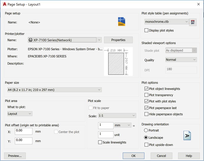
[ Chapter 4: Creating Orthographic Projections in AutoCAD® ]

CHAPTER SUMMARY

         In this chapter you will learn how to draw an orthographic projection in AutoCAD®. Layers
will be used which allow a drawing to contain different line types and to print using different line
widths. You will draw a title block and border that can be repeatedly used. By the end of this
chapter, you will be able to create a technically correct orthographic projection using proper line
types and weights.

4.1) INTRODUCTION

       An orthographic projection is a 2-D representation of a 3-D part. The line types
and line weights used to create the orthographic projection give valuable information to
the drawing or print reader. AutoCAD® enables you to draw orthographic projections
using different line types and to print drawings using different line weights. This is
accomplished through the use of layers.

4.2) LAYERS

        Layers are like transparencies, one placed over the top of another. Each
transparency/layer contains a different line type or a different part of the drawing. One
layer may be used to create visible lines, while another layer may be used to create hidden
lines. One layer may draw objects in red while another layer may draw objects in blue
and so on. Assigning a different line type and color to each layer helps you control and
organize the drawing. Before beginning to draw, many layers will be created and their
properties assigned. While drawing, the current or active layer (the layer you are drawing
on) will be switched from one to another depending on what feature of the drawing you
are working on.
        Figure 4.2-1 shows an orthographic projection that uses different line types and
line weights. The line type for each layer is set directly as a layer property. The line
thickness is controlled by the color in which it is drawn. Figure 4.2-2 shows a possible
layer organization scheme that could be used to create the orthographic projection shown
in Figure 4.2-2.
        Layers not only facilitate the use of line types and weights, but they can also help
you visualize, create and edit your work. For example, layers can be turned on or off.
This is very useful when using a projection/construction line. Construction lines are helpful
in the creation of an orthographic projection. However, they are not part of the final
drawing. It would be tedious if you had to erase all the construction lines individually. A
better way is to create a separate Construction layer and just turn it off (make it invisible)
when they are no longer needed. Layers can also be locked. This means that you can
see the layer but you cannot select any of the objects on the layer. This is very useful
when your drawing is very complex and you need to isolate objects that are on a particular
layer.

4-2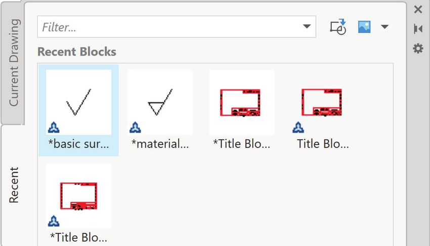
[ Chapter 4: Creating Orthographic Projections in AutoCAD® ]

Figure 4.2-1: A typical orthographic projection

                                                                            4-3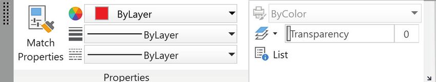
[ Chapter 4: Creating Orthographic Projections in AutoCAD® ]

                 Figure 4.2-2: Layer organization of an orthographic projection

4-4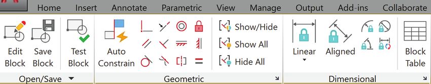
[ Chapter 4: Creating Orthographic Projections in AutoCAD® ]

4.2.1) The Layers panel

       The Layers panel is shown in Figures 4.2-3. The most frequently used
commands/areas in the Layers panel are the Layers Properties Manager icon and the
Layers pull-down selection menu. The Layers Properties Manager is used to create,
name, assign line types and manage layers. The Layers menu allows you to quickly switch
from one layer to the next and turn layers on and off.

        Layers                 Layers pull-down
        Properties             selection menu
        Manager

                               Figure 4.2-3: The Layers panel

The icons/features of the Layers panel are:

   •   Layers Properties Manager window:                   This icon brings up a Layers Properties
       Manager window. This window is the place where layers are created and the layer
       properties are assigned.
   •   Layer pull-down selection window: This pull-down window shows all of the available layers,
       allows you to switch between layers and enables you to change an object from one layer
       to another. To the left of each layer name is a set of quick access layer status settings that
       may be turned on or off. To turn these settings on and off, just click on them. Reading
       from left to right these settings are:
           o   On/Off:       The ON\OFF status of a layer is indicated by the light bulb. If it is
               yellow, the layer is ON and the objects on this layer can be seen. If it is gray, the
               layer is OFF and the objects on this layer cannot be seen.
           o   Freeze/Thaw:      The FREEZE/THAW status of a layer is indicated by two suns.
               The big yellow sun freezes/thaws all viewports and the small sun freezes/thaws

                                                                                                      4-5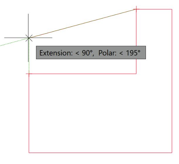
[ Chapter 4: Creating Orthographic Projections in AutoCAD® ]

                    only the current viewport. If a layer is FROZEN, the sun will turn into a snowflake.
                    Objects on a frozen layer are not displayed, regenerated, or plotted. Freezing
                    layers shortens regenerating time.

                o   Lock/Unlock:         The LOCK/UNLOCK status of a layer is indicated by the pad
                    lock. If the lock is open, the layer is UNLOCKED. The objects on this layer can
                    be seen and selected. If the lock is closed, the layer is LOCKED. The objects on
                    this layer can be seen but not selected.

    •    Layer States menu:                                        This is where you can save the
         current settings for layers in a named layer state and then restore those settings later.

    •    Layer Isolate:         This command locks all layers except the one you choose to isolate.

    •    Layer Unisolate:     This command unlocks all the layers that were locked while using
         the Layer Isolate command.

    •    Freeze:          Freezes a selected object’s layer.

    •    Off:        Turns a selected object’s layer off.

    •    Make Object’s Layer Current:               This icon sets the layer of a selected object to be the
         current one.

    •    Match:          Matches the layer of a selected object to a destination layer.

    •    Layer Previous:           This icon switches you back to your previous layer.

    •    Turn All Layers On:             Turns all the drawing layers on.

    •    Thaw All Layers:            Thaws all the drawing layers.

    •    Lock:         Locks a selected object’s layer.

    •    Unlock:          Unlocks a selected object’s layer.

    •    Change to Current Layer:               Changes the layer of a selected object to the current one.

    •    Copy Objects to New Layer:               Creates duplicates of the selected objects on a specified
         layer.

    •    Layer Walks:       Allows you to see all the objects on an individual layer while hiding the
         objects on the other layers.

    •    Isolate to Current Viewport:             Freezes select layers in all viewports except the current
         viewport.

    •    Merge:          Merges selected layers into a target layer.

    •    Delete:         Deletes all objects on a selected layer and then purges the layer.

    •    Locked Layer Fading:                                                 The locked layer fading may
         be set using this slider bar.

4-6
[ Chapter 4: Creating Orthographic Projections in AutoCAD® ]
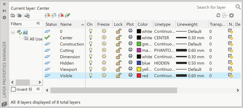
4.2.2) Layer properties
The Layer Properties Manager window is the place where you can create layers
and set their properties. This window may be accessed using the command LAYER or
by clicking on the Layer Properties Manager icon in the Layers panel. Figure
4.2-4 shows the Layer Properties Manager window with the important features identified.
Most of the features are self-explanatory except for the layer filter. The New Property
Filter window is a place where you may create filters based on one or more layer
properties. Right clicking on any layer name(s) accesses a shortcut menu with several
useful commands as shown in Figure 4.2-5.
New Property Create a Delete Set a layer
Filter new layer a layer current
Current
layer
Available Layer Layer
layers color line type
Figure 4.2-4: The Layer Properties Manager window
4-7[ Chapter 4: Creating Orthographic Projections in AutoCAD® ]
Figure 4.2-5: The Layer Properties Manager shortcut menu
Creating a new layer and setting layer properties
1) Command: LAyer or Layers panel:
2) Layer Properties Manager window:
a) Click on the New Layer icon
b) Name your layer.
c) Click on the square colored box under the heading Color. A Select Color window will
appear.
Name layer Click to change Click to change
layer color layer linetype
4-8[ Chapter 4: Creating Orthographic Projections in AutoCAD® ]
3) Select Color window – Index Color tab:
a) Select a color for your layer. It is
best to select a standard color.
Note: The color White and Black are
the same.
b) OK
Standard colors
4) Layer Properties Manager
window: Click on the name of the
line type under the heading
Linetype. A Select Linetype
window will appear.
5) Select Linetype window: If the
line type that you wish to use is
not Continuous, click on Load…
to select a different line type. A
Load or Reload Linetypes window
will appear.
6) Load or Reload Linetypes
window:
a) Scroll down until you find the
desired line type and select it.
b) OK
7) Select Linetype window:
a) Select the line type that you wish to assign to the layer.
b) OK.
8) Layer Properties Manager window: Close the window.
4-9[ Chapter 4: Creating Orthographic Projections in AutoCAD® ]
4.3) LINE TYPE SCALE
Line type scale only applies to lines that break, such as hidden lines, centerlines
and phantom lines. The line type scale determines the size of the dashes and the size of
the spaces between dashes or dots. You can control the line type scale either globally
(for all lines) or individually for each object. By default, both global and individual line type
scales are set to 1.00. The smaller the line type scale, the smaller the dashes and spaces.
The line type scale is adjusted according to your drawing size and the distance that a line
traverses. A short line segment that does not break and is displayed as continuous will
need to have a smaller line type scale. Figure 4.3-1 shows a centerline at three different
line type scales. The global line type scale may be set using the LTSCALE command.
Figure 4.3-1: The effects of line type scale
4.4) PROPERTIES
The properties of an individual object may be changed by selecting the object and
then selecting the Properties icon in the View tab - Palettes panel. Figure 4.4-1
shows the Properties window of a circle. Several properties such as object layer, line type
scale, and radius or diameter may be changed. Different objects will have different options
available in the Properties window. Properties may also be changed using the CHPROP
command.
4 - 10[ Chapter 4: Creating Orthographic Projections in AutoCAD® ]
Figure 4.4-1: Properties window for a circle
4.4.1) The Properties panel
The Properties panel (Figure 4.4-2) is located in the Home tab. It allows you to
change the color, line type and line weight of a selected object. It is my suggestion that
these properties always remain on ByLayer (the default properties of the object’s layer).
If you need to change one of these properties, your first action should be to move the
object to a layer that has those properties. This creates a much more organized drawing.
Changing the ByLayer settings in the properties toolbar should be reserved for occasional
use only. Two useful commands found in the Properties panel are Match Properties and
List. The LIST command lists the property data for a selected object.
Color Line weight
Line type List
Figure 4.4-2: The Properties panel
4 - 11[ Chapter 4: Creating Orthographic Projections in AutoCAD® ]
4.5) PRINTING USING PEN WIDTHS
The color of an object dictates the printed thickness of that object. This is why we
will specify a different color to each line type/layer. The pen widths are stored in files that
are computer specific. They are not stored in the drawing file. If you are using a public
computer, it is a good idea to check the pen width settings before printing.
You may print in color, grey scale or in black and white. If you are printing to an
inkjet and in color, you need to choose colors based on how they look. If you are printing
to a laser printer it is best to print in black and white and not in grey scale.
Setting pen widths
1) Menu browser: Print – Page Setup…
2) Page Setup Manager window: Modify…
3) Page Setup – Model window:
a) In the Plot style table (pen assignments) area, select
momochrome.ctb from the pull-down menu.
b) Question window (Assign this plot style table to all
layouts?): Yes
c) Select the Edit… icon next to the pull-down menu.
4) Plot Style Table Editor – monochrome.ctb window:
a) Plot styles field: Select a color
b) Lineweight field: Select the appropriate line weight
using the pull-down menu.
c) Repeat for all colors that you are using. Note that the print color in the Properties area
is always Black no matter what the Plot styles color is.
d) Save & Close
5) Page Setup – Model
window: OK
6) Page Setup Manager
window: Close
4 - 12[ Chapter 4: Creating Orthographic Projections in AutoCAD® ]
4.6) CREATING LAYERS TUTORIAL
The objective of this tutorial is to create a set of standard layers that will be used
to create orthographic projections. These layers will be saved to a template file so that
they can be used repeatedly.
4.6.1) Setting drawing parameters
1) View the Layers video and read sections 4.1) through 4.5).
2) Open your set-inch.dwt. Your set-inch template file should have the following
settings. If it does not, change them at this point.
• UNITS
a. Units = inches
b. Precision = 0.00
• LIMITS = 11,8.5
• STyle
a. Text font = Arial
b. Text height = 0.12
c. Make sure the Annotative toggle is checked.
3) Set the global line type scale to 0.5.
a) Command: ltscale
b) Enter new linetype scale factor : 0.5
4.6.2) Creating layers
1) Command: la or Layers panel:
2) Layer Properties Manager window:
a) Click on the New Layer icon
b) Name your layer Hidden.
c) Click on the square colored box under the heading Color that is associated with
the Hidden layer. A Select Color window will appear.
Name layer Click to change Click to change
layer color layer linetype
4 - 13[ Chapter 4: Creating Orthographic Projections in AutoCAD® ]
3) Select Color window – Index Color tab:
a) Select the color Blue from the
standard colors bar.
b) OK
Blue
4) Layer Properties Manager window: Click on the name of the line type under the
heading Linetype that is associated with the Hidden layer. A Select Linetype window
will appear.
5) Select Linetype window: Click
on Load…. A Load or Reload
Linetypes window will appear.
6) Load or Reload Linetypes
window:
a) Scroll down until you find the
HIDDEN line type and select
it.
b) OK
7) Select Linetype window:
a) Select the HIDDEN line type.
b) OK.
4 - 14[ Chapter 4: Creating Orthographic Projections in AutoCAD® ]
8) In a similar fashion, create the following layers.
• Visible, color = red, linetype = Continuous
• Center, color = white/black, linetype = CENTER
• Dimension, color = white/black, linetype = Continuous
• Cutting, color = magenta, linetype = PHANTOM
• Construction, color = green, linetype = Continuous
• Viewport, color = yellow, linetype = Continuous
9) set-inch.dwt.
4.6.3) Drawing on different layers
1) Layers Tut.dwg.
2) Draw a line on each layer to see if the
layer properties were set correctly.
a) Set the Visible layer to be current.
i. Layers panel: Expand the Layer
pull-down menu and select
Visible.
b) Draw a Line. It should be red.
c) Set the Hidden layer to be current and
draw 2 Lines. They should be blue
and dashed.
d) Repeat for all the other layers.
4 - 15[ Chapter 4: Creating Orthographic Projections in AutoCAD® ]
4.6.4) Line type scale
1) Change the global line type scale (LTSCALE) to 0.25. Notice that the dashes and
spaces between the dashes become smaller.
How?
a) Command: ltscale
b) Enter new linetype scale factor : 0.25
2) Change your LTSCALE to 1.
3) Change your LTSCALE back to 0.5.
4) Change the line type scale of one of the hidden
lines to twice that of the global line type scale.
a) Select one of the hidden lines.
b) View tab - Palettes panel:
c) Properties window: Change the Linetype
scale to 2.
5) Save and print your drawing.
Exercise 4.6-1: Creating layers
Open your set-mm.dwt, make sure that it has the following settings and create
the layers indicated. Then, resave your template file.
Settings:
• UNITS (Millimeters, Precision = 0)
• LIMITS = 297,210
• STyle (Text font = Arial, Text height = 3, Annotative)
• LTSCALE = 0.5
Layers:
• Visible, color = red, linetype = Continuous
• Hidden, color = blue, linetype = HIDDEN
• Center, color = white/black, linetype = CENTER
• Dimension, color = white/black, linetype = Continuous
• Cutting, color = magenta, linetype = PHANTOM
• Construction, color = green, linetype = Continuous
• Viewport, color = yellow, linetype = Continuous
4 - 16[ Chapter 4: Creating Orthographic Projections in AutoCAD® ]
4.7) BLOCKING
Blocks are a grouping of objects that can be used repeatedly. The command
BLOCK allows you to define a particular drawing as an entity. It groups all the lines,
circles, and other geometric shapes into one entity. This means that you can insert this
group into a drawing without having to redraw it. The commands that are relevant for
creating and using blocks are grouped in the Block panel shown in Figure 4.7-1.
Figure 4.7-1: Block panel
The commands contained in the Block panel and the other commands related to
blocking are:
• INSERT: The INSERT command allows you to retrieve an existing block or
wblock.
• BLOCK: The BLOCK command allows you to create a grouping of objects
that can be used repeatedly in the current drawing. Blocks are inserted as entities,
which means that they can’t be edited by erasing parts of them or breaking lines within
them unless you use the BEDIT command or EXPLODEing the block first.
• BEDIT: The block edit command allows you to select and edit an existing
block. The block edit command temporarily adds a Block Editor tab to the ribbon as
shown in Figure 4.7-2.
Figure 4.7-2: Block Editor tab
4 - 17[ Chapter 4: Creating Orthographic Projections in AutoCAD® ]
• WBLOCK: This command writes a block to a file. This allows you to use the block in
all drawings not just the current one.
• EXPLODE: Allows you to separate a block into its individual parts. The
EXPLODE command may be accessed in the Modify panel.
• BASE (Set Base point): Set the insertion base point for the current drawing.
The base point is the reference point used when creating and inserting your block.
This point should not be arbitrary. It should have some relationship with the block and
with the object or space in which it will be inserted.
Creating blocks
1) Command: block or Block panel:
2) Block Definition window:
a) Name the block.
b) Base point area: Pick a base point/insertion point. This can be accomplished by directly
entering a coordinate or by selecting the Pick point icon.
c) Objects area:
i. Select all objects that you wish to include in the block definition using the Select
objects icon. (The objects may also be selected before entering the BLOCK
command.)
ii. Activate either the Retain (keeps the original object as is), Convert to block (converts
the original object to a block) or Delete (deletes the original object) radio button.
d) Behavior area: Activate Allow exploding and Annotative checkboxes.
e) If necessary, set the Block units.
f) OK
Note: A block is defined within the current drawing and cannot be used in other drawings unless
a WBLOCK is created.
4 - 18[ Chapter 4: Creating Orthographic Projections in AutoCAD® ]
Creating a wblock
1) Command: wblock
2) Write Block window:
a) Select the Block radio button.
b) Select the block you wish to write to a file in the pull-down menu.
c) Select a location for the file by clicking on the file path icon .
d) Select the Insert units.
e) OK
4 - 19[ Chapter 4: Creating Orthographic Projections in AutoCAD® ]
Inserting a block or wblock
1) Command: insert or Block
panel:
a) When you select the Insert icon,
you will get a dropdown menu
that has your drawing block.
Select the block you wish to
insert and place it in your
drawing or select Blocks from
Libraries.
b) When you type the command
insert or select Recent
Blocks…, Favorite Blocks…,
or Blocks from Libraries…
from the above pulldown menu,
you will get a Blocks window.
Select the block you wish to insert and place it in your drawing. Note that, from this
window, you can change the block’s scale, rotation, place it repeatedly and explode it.
Blocks Allows you to choose
a block from a file.
Block modifications.
4 - 20[ Chapter 4: Creating Orthographic Projections in AutoCAD® ]
4.8) MODEL AND LAYOUT SPACE
4.8.1) Model space
In model space, you draw your design at a 1:1 scale. You specify whether one
unit represents one millimeter, one centimeter, one inch, one foot, or whatever unit is most
convenient. If you are going to create a 2-D orthographic projection, you can create both
the model (drawing) and annotations (dimensions), and print entirely from within model
space. This method is simple but has several limitations including:
• It is suitable for drawings that are viewed from only one direction. 2-D drawings
are only viewed from one direction, but 3-D drawings may have many viewing
directions.
• It does not support multiple views and view dependent layer settings.
• Scaling the annotations and title block requires computation. This is because if
you change the scale of the model the annotations change with it.
With this method, you always draw geometric objects at full scale (1:1) and text,
dimension and other annotations at a scale that will appear at the correct size when the
drawing is plotted.
4.8.2) Layout space
In paper/layout space, you can place objects and annotations that are not part of
your design such as a title block and dimensions. In paper space, you see what will be
printed (usually on an 8.5 x 11 sheet of paper). Therefore, objects from the model space
that are larger than the paper are scaled to fit the available printing area.
You can plot objects that are in the model space from paper space using viewports.
A viewport is a rectangular window that views the object from a specified line of sight.
Viewports are most useful when working with a 3-D model. In this situation, you can create
several viewports that view the 3-D model from several different vantage points. When
looking at a 2-D drawing, you really only want to view the xy plane. A situation where you
might use multiple viewports with a 2-D drawing is if you are showing part of the model at
a different scale. The command VIEWPORTS may be used to create additional viewports.
In paper space, each layout viewport is like a picture frame containing a
photograph of the model. Each layout viewport contains a view that displays the model at
an independent scale and orientation that you specify. You can also specify different
layers properties in each layout viewport. The advantages of plotting from paper space
are:
• You can plot multiple viewports.
• The size and location of the objects within each viewport is completely within your
control.
• With annotative scaling, it is not necessary to calculate the appropriate dimension
and text scale. Annotative scaling will be discussed in detail in the “Dimensioning
in AutoCAD®” chapter. Figure 4.8-1 shows an example of what you would see in
paper space before plotting.
4 - 21[ Chapter 4: Creating Orthographic Projections in AutoCAD® ]
Viewport border
The views of the orthographic
projection are in model space.
Accesses Border of the paper Border of the
paper space (usually 8.5x11) printable area
Accesses The title block and border
model space are in paper space.
Figure 4.8-1: Paper space
4 - 22[ Chapter 4: Creating Orthographic Projections in AutoCAD® ]
4.9) CENTERLINES
Center lines are used to indicate axis of symmetry among other things. AutoCAD®
has specialized commands for creating center marks for circles and arcs as well as center
lines for axes of symmetry. Both the CENTERLINE and CENTERMARK commands
create lines that are associative. Which means that they are attached to and change with
the particular geometry that was used to define them. Figure 4.9-1 shows the Centerlines
panel which is located in the Annotate tab.
Center lines and center marks may be edited through the use of grip boxes or in
the Properties window (View tab – Palettes panel). If you click on either a center
mark or center line, grip boxes will appear allowing you to extend or shorten the line.
Figure 4.9-2 shows a grip boxes modification example. Several of the center mark or
center line features may be adjusted within the Properties window. For example, for a
center mark, the cross size and cross gap may be changed. Figure 4.9-3 shows the
Properties window for both a center mark and a center line.
Figure 4.9-1: Centerlines panel
Figure 4.9-2: Grip box modification of a center mark
4 - 23[ Chapter 4: Creating Orthographic Projections in AutoCAD® ]
Figure 4.9-3: Center mark and center line Properties window
4 - 24[ Chapter 4: Creating Orthographic Projections in AutoCAD® ]
4.10) TITLE BLOCK TUTORIAL
Every engineering drawing should have both a border and a title block. The
border defines the drawing area and the title block gives pertinent information about the
part or assembly being drawn. There are several different types of title blocks, but they
all contain similar information. The information that is included depends on the drawing
type, field of engineering, and viewing audience. The title block specified in the ASME
Y14.100 standard is described in the chapter on “Introduction to Engineering Drawings”.
4.10.1) Blocking a title block
1) View the Blocking video and read section 4.7).
2) titleblock_student_A_2018.dwg. You will see a basic title block meant
to fit an A sized sheet (i.e. 8.5 x 11.)
3) Fill in all the standard information into your title block. To edit the text, just double click
on it, or you can use the command DDEDIT.
a) COMPANY NAME = Enter your company or university name.
b) DRAFTER = Enter your initials.
4) Zoom All
4 - 25[ Chapter 4: Creating Orthographic Projections in AutoCAD® ]
5)
6) BLOCK your title block and border.
a. Command: block or Home Ribbon - Block panel:
b. Block Definition window:
i. Name the block Title Block A.
ii. Enter a Base point of 0.00, 0.00, 0.00
iii. Select all objects that make up your title block and border using the Select
objects icon. Hit the Enter key after you have selected your objects to
return to the Block Definition window.
iv. Activate the Retain radio button.
v. Activate the Annotative and Allow exploding checkboxes.
vi. Set the Block units to Inches.
vii. OK
4 - 26[ Chapter 4: Creating Orthographic Projections in AutoCAD® ]
7) Write the Title Block A block to a file.
a) Command: wblock
b) Write Block window:
i.Select the Block radio button.
ii.Select the Title Block A block from the pull-down menu.
iii.Select a location for the file by clicking on the file path icon and name the
file Title Block A.
iv.Select Inches as the insert units.
v.OK
4.10.2) Blocking a metric title block
The Metric sheet size that is closest to an A size sheet (i.e. 11 x 8.5 inches) is the
A4 sheet which is 297 x 210 mm (i.e. 11.7 x 8.3 inches).
1) View the Blocking video and read section 4.7).
2) titleblock_student_A4_2018.dwg and Title Block A4.dwg.
You will see a basic title block meant to fit an A4 sized sheet (i.e. 297 x 210 mm)
3) Fill in all the standard information into your title block. To edit the text, just double click
on it, or you can use the command DDEDIT.
a) COMPANY NAME = Enter your company or university name.
b) DRAFTER = Enter your initials.
4) Zoom All
5)
4 - 27[ Chapter 4: Creating Orthographic Projections in AutoCAD® ]
6) BLOCK your title block and border.
a. Command: block or Block panel:
b. Block Definition window:
i. Name the block Title Block A4.
ii. Enter a Base point of 0.00, 0.00, 0.00
iii. Select all objects that make up your title block and border using the Select
objects icon. Hit the Enter key after you have selected your objects to
return to the Block Definition window.
iv. Activate the Retain radio button.
v. Activate the Annotative and Allow exploding checkboxes.
vi. Set the Block units to Millimeters.
vii. OK
4 - 28[ Chapter 4: Creating Orthographic Projections in AutoCAD® ]
7) Write the Title Block mm block to a file.
c) Command: wblock
d) Write Block window:
i. Select the Block radio button.
ii. Select the Title Block A4 block from the pull-down menu.
iii. Select a location for the file by clicking on the file path icon and name the
file Title Block A4.
iv. Select mm as the insert units.
v. OK
Exercise 4.10-1: Creating Blocks
Open titleblock_student_B_2018. This is a title block that will fit a B sized
sheet of paper (17 x 11 inches). Open titleblock_student_A3_2018. This is
a title block that will fit an A3 sized sheet of paper (420 x 297 mm). Block
and Wblock each title block for use later.
4 - 29[ Chapter 4: Creating Orthographic Projections in AutoCAD® ]
4.11) ORTHOGRAPHIC PROJECTION TUTORIAL
By the end of this tutorial you will have created and printed an orthographic
projection of the part shown using proper pen widths. We will draw the orthographic
projection using the procedure explained in the chapter on “Orthographic Projections”. We
will start by drawing the front view and use projectors to construct the top and right side
views. Visible, hidden, and centerlines will be drawn on their own layer. Once the drawing
is complete we will use both the model space and the layout space to plot the drawing.
4.11.1) Draw the front view
1) View the Model - Layout, Pen widths and Printing videos and read sections 4.8) and
4.9).
2) Take some time to sketch what you think the FRONT, TOP and RIGHT SIDE views of
the above object will look like.
3) set-inch.dwt and Ortho Tut.dwg. Save periodically
throughout this tutorial.
4 - 30[ Chapter 4: Creating Orthographic Projections in AutoCAD® ]
4) Enter your WCS .
5) If you are using Dynamic Input, set the Pointer Input Format to Absolute coordinates.
6) In the Viewport layer, draw a RECtangle that indicates the edges of your limits/paper
(11x8.5).
7) Zoom All
8) In your Visible layer, draw the visible lines of the front view.
a) Draw a RECtangle that is 3 inches long and 2 inches wide near the bottom left
corner of your drawing area.
b) Set your UCS origin to the bottom left corner of the front view.
c) Draw the 2 Lines within the rectangle.
d) Draw the Circle. (Note: n = diameter)
Note: Some visible features are missing, but this is all we can do for now.
4.11.2) Drawing the right side view
1) Turn your Object Snap on and set the following object snaps to be automatically
detected (Endpoint, Midpoint, Center, Quadrant, Intersection, Nearest, Perpendicular,
Extension).
4 - 31[ Chapter 4: Creating Orthographic Projections in AutoCAD® ]
2) In the Construction layer, draw horizontal and vertical construction lines (XLine) off
of every edge and boundary of the front view.
a) Create the horizontal projectors.
i. Command: xl or Draw panel:
ii. Specify a point or [Hor/Ver/Ang/Bisect/Offset]: h
iii. Specify through point: Select every corner, edge and quadrant that
should have a horizontal projector coming off of it.
iv. Specify through point: Enter
b) Create the vertical projectors.
c) Move the visible lines of the front view above the construction lines.
i. Home tab - Modify panel:
ii. Select objects: Using a window, select all the visible lines of the front view.
iii. Select objects: Enter
4 - 32[ Chapter 4: Creating Orthographic Projections in AutoCAD® ]
3) In the Visible layer, draw the visible features of the L-shaped part of the right side
view.
How?
1) Command: line or
2) Specify first point: Select a point that is NEArest Projector 1. (See
the figure below.)
3) Specify next point or [Undo]: @2[ Chapter 4: Creating Orthographic Projections in AutoCAD® ]
4) Draw the angled feature of the right
side view using the following
commands.
a) Turn the Polar Tracking on
and set POLARANG to 15
degrees.
b) Use a polar tracking path and
the EXTension snap to
construct the angled line.
c) Connect the angled line with
the L-shaped body.
5) In the Construction layer, project the angled feature of the right side view back to the
front view.
6) In the Visible layer, draw the missing visible lines in the front view.
7) In the Hidden layer, draw the rectangular view of the hole in the right side view.
4 - 34[ Chapter 4: Creating Orthographic Projections in AutoCAD® ]
4.11.3) Drawing the top view
1) In the Construction layer, draw the projectors needed to complete the top view.
a) Draw a 45o projector off the upper right corner of the front view.
i. Command: xl or Draw panel:
ii. Specify a point or [Hor/Ver/Ang/Bisect/Offset]: a
iii. Enter angle of xline (0) or [Reference]: 45
iv. Specify through point: Select the upper right corner of the front view.
v. Specify through point: Enter
b) Draw vertical projectors up from the right side view and horizontal projectors over
to where the top view will be located.
c) Use the icon to bring the lines of the right side view to the front.
4 - 35[ Chapter 4: Creating Orthographic Projections in AutoCAD® ]
2) Draw the visible and hidden features of the top view.
3) Turn the Construction layer off.
Click on the light bulb
to turn the layer off.
4 - 36[ Chapter 4: Creating Orthographic Projections in AutoCAD® ]
4.11.4) Drawing centerlines
1) In the Center layer, add the center mark for the hole in the front view.
a) Annotate Tab – Centerlines panel: or CENTERMARK
b) Select circle or arc to add centermark: Click on the circle.
2) Add the centerlines in the right side and top views.
a) Annotate Tab – Centerlines panel: or CENTERLINE
b) Select first line: Click on one of the lines that will define the centerline
location.
c) Select second line: Click on the other line.
Note: Don’t worry if your centerlines don’t look correct. We will fix them later.
4 - 37[ Chapter 4: Creating Orthographic Projections in AutoCAD® ]
3) Notice that the center mark and centerlines have
very small dashes. Let’s fix that.
a) Click on the center mark.
b) View tab – Palettes panel:
c) Change the Cross size to 0.3x and the Cross
gap to 0.1x.
d) Change all of the extensions to 0.12.
4) Fix the centerlines.
a) Click on both of the centerlines.
b) View tab – Palettes panel:
c) Change the Linetype to CENTER instead of
CENTER2.
d) Change the Start and End extension to 0.12.
5) Make sure that all three views are within the limits rectangle that you drew.
4 - 38[ Chapter 4: Creating Orthographic Projections in AutoCAD® ]
6)
4.11.5) Printing the layout
1) Select the Layout1 tab at the bottom of your drawing screen.
2) Insert your inch title block.
a) Command: insert or Block panel: and then Blocks from
Libraries…
b) Choose the Title Block A block file.
c) Check the Insertion Point check box. This will allow you to choose an insertion
point on the screen.
Select to choose file.
d) Select the Title Block A picture and manually specify an insertion point to be just
inside the lower left corner of the printable area. The printable area is indicated by
a light line. This should be the biggest rectangle shown on the page. The size of
this area depends on the type of printer being used. (See the figure below.)
4 - 39[ Chapter 4: Creating Orthographic Projections in AutoCAD® ]
3) Notice the features of the layout (see the figure below). At this point, you should see…
• The border of the 8.5x11 sheet of paper.
• The border of the printable area. The size of the printable area is printer
dependent.
• The viewport border.
• The orthographic projection is in model space.
• The rectangle that you drew to indicate the 11x8.5 limits (yellow). Therefore the
objects in the model are not being shown at a 1:1 scale relative to paper space.
• Note that your title block is too big. We will take care of that later.
Border of the
printable area
Viewport border
Limits rectangle
Border of the 8.5x11
sheet of paper
4) Move your viewport border to the Viewport layer.
5) Scale your title block using the lower left-hand corner as the base point. The scale
percentage depends on your printer selection. For me it was 93%.
6) Use the Move command to center your title block within the printable area.
4 - 40[ Chapter 4: Creating Orthographic Projections in AutoCAD® ]
7) Click on the viewport border to activate its grip boxes. Using the grip boxes, resize
the viewport border so that it is just inside your title block border. Caution! Don’t make
it the same size as your title block border. We will need to access the viewport border
often.
8) With the view port still selected, notice that a Viewport
Scale is added to the Status bar. The Viewport Scale
indicates the scale at which objects within the view port are
shown relative to the paper space. If you have more than
one view port, each view port may have a different scale.
9) Click on the Viewport Scale and change it to 1:1. Viewport
Scale
10) Double click inside the viewport border. This activates the
model space and the viewport border will thicken. Use the
Pan and Move commands so that the orthographic
projection is centered within the title block border. Double
click outside the viewport border to re-enter paper space.
11) Turn OFF your Viewport layer.
4 - 41[ Chapter 4: Creating Orthographic Projections in AutoCAD® ]
12) Fill in your title block. In order to enter text, we need to break the title block into its
individual entities.
a) Command: explode or Modify panel:
b) Select objects: Select any part of the title block.
c) Select objects: Enter
13) Edit your text by using the DDEDIT command or by double click on the word to edit.
Enter the following information.
a) PART NAME = ANGLE BLOCK
b) SIZE = A
c) SCALE = 1:1
d) DWG NO = 123
e) WEIGHT = delete the ?.
f) SHEET = 1 OF 1
g) DATE = Enter the appropriate date
h) MATERIAL = ALUMINUM
i) FINISH = ALL OVER
4 - 42[ Chapter 4: Creating Orthographic Projections in AutoCAD® ]
14) Set your pen widths and prepare to print.
a) Application button: Print – Page Setup… or Layout Tab:
b) Page Setup Manager window: Modify…
c) Page Setup – Layout1 window:
i. Select a printer.
ii. Plot the Layout.
iii. Select a 1:1 scale.
iv. Plot style table (pen assignments) area: Select monochrome.ctb from the
pull-down menu.
v. Select the Edit… icon next to the pull-down menu. A Plot Style Table
Editor window will appear.
d) Plot Style Table Editor – monochrome.ctb window:
iii. Plot styles field: Select Color 1 (red – visible line color).
iv. Lineweight field: Select 0.6000 mm from the pull-down menu.
v. Follow the same procedure to set the widths of the other lines types.
• Color 5 (blue – hidden) = 0.45 mm
• Color 7 (black – center and dimension lines) = 0.3 mm
vi. Save & Close
e) Page Setup – Layout1 window: OK
f) Page Setup Manager window: Close
Note: Every setting except the pen widths are saved within the drawing file and
will not change unless you change them. The pen widths are computer specific
and will have to be re-entered if you change computers.
Note: You may also set pen width within the Layers Properties Manager if you
find this easier (see figure below). However, this method gives you a limited
number of pen widths. Therefore, you notice that the hidden line is given a pen
width of 0.50 mm when a better width is 0.45 mm.
Pen widths
4 - 43[ Chapter 4: Creating Orthographic Projections in AutoCAD® ] 4 - 44
[ Chapter 4: Creating Orthographic Projections in AutoCAD® ]

15) Plot your drawing.
     a) Application button: Print – Plot….
     b) Plot - Layout1 window: Preview…
     c) Hit Esc to exit print preview.
     d) If the preview did not appear as you expected, adjust your settings and
         Preview... the drawing again. Check to make sure your pen widths are set
         correctly and your line breaks look right.
     e) Plot - Layout1 window: Select OK when everything is set correctly.

16) Switch back to your model space by clicking the Model tab at the bottom of the
    drawing screen. Notice that your title block disappears. This is because layout
    objects do not appear in the model space.

17)

                                                                                               4 - 45
[ Chapter 4: Creating Orthographic Projections in AutoCAD® ]
4.11.6) Printing a metric drawing
1) ortho_metric_student_2018.dwg. This file contains a metric version of
the orthographic projection completed in the previous sections.
2) Ortho Metric Tut.dwg
3) Verify that the drawing is indeed metric. On the Viewport layer, draw a limits
RECtangle that is 297 x 210 mm whose lower left corner starts at 0,0.
4) Zoom All
5) Enter Layout space.
6) Move your viewport border to the Viewport layer.
View port
border
Limits rectangle
7) Enter the Page Setup – Layout1 window (Print – Page Setup…- Modify) and set the
following parameter.
a) Paper size = A4 (210 x 297 mm).
b) Plot scale area:
i. Scale = 1:1
c) Plot style = monochrome.ctb
4 - 46[ Chapter 4: Creating Orthographic Projections in AutoCAD® ]
8) INSERT your A4 metric title block, center the title block and SCale (if
necessary) to fit within your printable area.
9) Fill in your title block, adjust your view port border, set the Viewport Scale to 1:1,
center your model, turn the Viewport layer off, fill in your title block, save and print
your drawing. Note, you will have to EXPLODE your title block in order to fill in the
fields. (See figure on the next page.)
4 - 47[ Chapter 4: Creating Orthographic Projections in AutoCAD® ] 4 - 48
[ Chapter 4: Creating Orthographic Projections in AutoCAD® ]

ORTHOGRAPHIC PROJECTIONS IN AUTOCAD QUESTIONS

Name: _________________________________ Date: _______________

Layers

Q4-1) The layer you are drawing on is said to be ....

   1.    on.
   2.    first.
   3.    on top.
   4.    current.

Q4-2) What layer property controls an entity's printed width?

   a)    line type
   b)    layer name
   c)    color
   d)    pen style

Q4-3) The construction layer is used to create projection lines. When the orthographic
projection is complete, we do not need these lines anymore. The easiest way to not
show the projections lines is to turn the construction layer to the ________ state.

   a)    freeze
   b)    thaw
   c)    off
   d)    on

Q4-4) Lines occurring on a LOCKED or OFF layer may not be selected. Which layer
status still allows you to see the lines?

Q4-5) The place/window where you can change a layer’s color, linetype and status.

   a) Layer properties manager
   b) Layers manager
   c) Layer status manager

Q4-6) The typed command that is used to control the length of the dashes and spaces
of the different line types.

   a)    ltscale
   b)    scale
   c)    dashscale
   d)    setscale

                                                                                                 4 - 49
[ Chapter 4: Creating Orthographic Projections in AutoCAD® ]
Q4-7) To change the line type scale of an individual object, you must enter the .... window.
a) scale
b) properties
c) line type
d) page setup
Blocking
Q4-8) A grouping of objects that may be reused.
a) group
b) nest
c) pair
d) block
Q4-9) What typed command is used to write a block to a file?
a) block
b) create
c) wblock
d) insert
Q4-10) The command used to break a block up into its individual components.
a) ungroup
b) explode
c) break apart
d) Insert
4 - 50[ Chapter 4: Creating Orthographic Projections in AutoCAD® ]
Name: _________________________________ Date: _______________
Model/layout space and printing
Q4-11) The space where you see exactly what is going to be printed. (circle all that apply)
a) model
b) layout
c) paper
d) real
Q4-12) An area within layout space that allows you to view objects within model space
and to scale these objects with respect to the printed page.
a) viewport
b) model view
c) paper space
Q4-13) How do you access model space while still remaining in paper space?
a) Click on the model tab.
b) Double click within the viewport border.
c) Type “model”
d) Click on the viewport border.
Q4-14) The typed command that allows you to create a new viewport.
a) viewports
b) port
c) newport
d) newview
Q4-15) What pen styles table is used if you want to print in black and white?
a) color
b) gray
c) black and white
d) monochrome
Q4-16) The typed command used to edit existing text.
a) ddedit
b) edit
c) text edit
d) tedit
4 - 51[ Chapter 4: Creating Orthographic Projections in AutoCAD® ]
NOTES:
4 - 52[ Chapter 4: Creating Orthographic Projections in AutoCAD® ]
ORTHOGRAPHIC PROJECTIONS IN AUTOCAD PROBLEMS
P4-1) Create an orthographic projection of the following object. Draw the three
standard views.
P4-2) Create an orthographic projection of the following object. Draw the three
standard views.
4 - 53[ Chapter 4: Creating Orthographic Projections in AutoCAD® ] P4-3) Create an orthographic projection of the following object. Draw the three standard views. 4 - 54
[ Chapter 4: Creating Orthographic Projections in AutoCAD® ]

P4-4) Create an orthographic projection of the following object. Draw the three
standard views.

P4-5) Create an orthographic projection of the following object. Draw the three
standard views.

                                                                                                4 - 55
[ Chapter 4: Creating Orthographic Projections in AutoCAD® ] P4-6) Create an orthographic projection of the following object. Draw the three standard views. 4 - 56
[ Chapter 4: Creating Orthographic Projections in AutoCAD® ]

P4-7) Create an orthographic projection of the following object. Draw the three
standard views.

P4-8) Create an orthographic projection of the following object. Draw the three
standard views.

                                                                                                4 - 57
[ Chapter 4: Creating Orthographic Projections in AutoCAD® ] P4-9) Create an orthographic projection of the following object. Draw the three standard views. 4 - 58
[ Chapter 4: Creating Orthographic Projections in AutoCAD® ]

P4-10) Create an orthographic projection of the following object. Draw the three
standard views.

                                                                                               4 - 59
[ Chapter 4: Creating Orthographic Projections in AutoCAD® ] P4-11) Create an orthographic projection of the following object. Draw the three standard views. 4 - 60
[ Chapter 4: Creating Orthographic Projections in AutoCAD® ]

P4-12) Create an orthographic projection of the following object. Draw the three
standard views.

                                                                                               4 - 61
[ Chapter 4: Creating Orthographic Projections in AutoCAD® ] P4-13) Create an orthographic projection of the following object. Draw the three standard views. 4 - 62
[ Chapter 4: Creating Orthographic Projections in AutoCAD® ]

P4-14) Create an orthographic projection of the following object. Draw the three
standard views.

                                                                                               4 - 63
[ Chapter 4: Creating Orthographic Projections in AutoCAD® ] P4-15) Create an orthographic projection of the following object. Draw the three standard views. P4-16) Create an orthographic projection of the following object. Draw the three standard views. 4 - 64
[ Chapter 4: Creating Orthographic Projections in AutoCAD® ]

P4-17) Create an orthographic projection of the following object. Draw the three
standard views.

                                                                                               4 - 65
[ Chapter 4: Creating Orthographic Projections in AutoCAD® ] P4-18) Create an orthographic projection of the following object. Draw the three standard views. 4 - 66
You can also read