EUROSYSTEM V8 Original Operating Instructions - Software for Safety Test Lanes - MAHA Maschinenbau Haldenwang ...
←
→
Page content transcription
If your browser does not render page correctly, please read the page content below

EUROSYSTEM V8
Software for Safety Test Lanes

Original Operating Instructions
BAE13101-en
2

 BAE13101-en
 2021-02-15
 © MAHA Maschinenbau Haldenwang GmbH & Co. KG
 The reproduction, distribution and utilization of this document as well as the communication of its
 contents to others without explicit authorization is prohibited. Offenders will be held liable for the
 payment of damages. All rights reserved in the event of the grant of a patent, utility model or de-
 sign.
 The contents of this edition have been checked with great care. However, errors cannot be fully
 excluded. Subject to technical change without notice.
 Manufacturer                                                     Service
 MAHA Maschinenbau Haldenwang GmbH & Co. KG                       MAHA SERVICE CENTER
 Hoyen 20                                                         Maybachstraße 8
 87490 Haldenwang                                                 87437 Kempten
 Germany                                                          Germany
 Phone: +49 8374 585-0                                            Phone: +49 8374 585-100
 Fax: +49 8374 585-590                                            Fax: +49 8374 585-491
 Mail: maha@maha.de                                               Mail: service@maha.de
 Web: www.maha.de                                                 Web: www.mahaservicecenter.de

BAE13101-en

3

Content
1       General safety instructions ................................................................................. 7
1.1     Introduction ..................................................................................................................... 7
1.2     Symbols and signal words ............................................................................................. 7
1.3     Procedure in the event of a malfunction ...................................................................... 7
1.4     Procedure in the event of an accident .......................................................................... 8
1.5     Requirements for operators and service personnel .................................................... 8
1.6     Observance of the operating instructions .................................................................... 8
1.7     Installation requirements ............................................................................................... 8
2       Installation and configuration ............................................................................. 9
2.1     Start set-up from DVD .................................................................................................... 9
2.2     Software download....................................................................................................... 12
2.3     Unattended set-up ........................................................................................................ 13
2.4     Recommendations and restrictions ............................................................................ 14
3       System requirements ........................................................................................ 15
4       Licensing .......................................................................................................... 16
4.1     Test period .................................................................................................................... 16
4.2     Activation....................................................................................................................... 16
5       Operation .......................................................................................................... 18
5.1     Main menu and screen elements ................................................................................ 18
5.2     Start and end program ................................................................................................. 20
5.3     Virtual remote control................................................................................................... 21
6       Test procedure ................................................................................................. 22
6.1     Side slip test .................................................................................................................. 22
6.2     Shock absorber test ..................................................................................................... 23
6.3     Brake test ...................................................................................................................... 24
6.3.1   Ovality test ..................................................................................................................... 25
6.3.2   Brake efficiency test ..................................................................................................... 25
6.4     Leaving the test lane or the test stand........................................................................ 26
6.5     Intervention in the automatic test sequence .............................................................. 27
7       Perform visual inspection ................................................................................. 28
7.1     Entering and saving visual defects ............................................................................. 28
7.2     Displaying the listed defects........................................................................................ 30
8       Save measurement ........................................................................................... 30
8.1     Assignment after the test ............................................................................................ 31
8.2     Assignment before the test ......................................................................................... 31
8.3     Prepare new vehicle inspection ................................................................................... 32
                                                                                                                              BAE13101-en
4

9         Customer and vehicle management .................................................................. 32
9.1       File specification ........................................................................................................... 32
9.2       Load master data.......................................................................................................... 33
9.3       Complete data entry ..................................................................................................... 33
9.4       Delete measurements .................................................................................................. 34
9.5       Redisplay measurements............................................................................................. 34
10        Brake test ......................................................................................................... 35
10.1      Final evaluation of brake test ...................................................................................... 37
10.1.1 Total weight has already been recorded..................................................................... 37
10.1.2 Total weight was not recorded .................................................................................... 37
11        Shock absorber test .......................................................................................... 38
12        Side slip test ..................................................................................................... 38
13        Test without predefinition ................................................................................. 39
14        Safety inspection .............................................................................................. 41
15        Define automatic measurement ........................................................................ 42
16        Administration .................................................................................................. 44
16.1      Database (Administrator) ............................................................................................ 44
16.2      Delete measurements individually .............................................................................. 45
16.3      Delete measurements via date range ......................................................................... 45
16.4      Delete measurements via ID number range ............................................................... 46
16.5      Delete all open tests ..................................................................................................... 46
16.6      Backup of the database ............................................................................................... 46
16.7      Restoring the databases .............................................................................................. 47
16.8      Transfer data from an external EDP............................................................................ 47
16.9      Table export / import / delete ...................................................................................... 47
16.10     Test equipment (QA representative) ........................................................................... 48
16.11     Old measurements ....................................................................................................... 48
16.12     Export measurements .................................................................................................. 49
16.13     Import measurements .................................................................................................. 49
16.14     Customer master data ................................................................................................. 50
16.15     Vehicle master data...................................................................................................... 50
16.16     Complete vehicle master data ..................................................................................... 51
17        User .................................................................................................................. 51
18        Settings ............................................................................................................ 52
19        Diagnostics ....................................................................................................... 53
20        Print all settings................................................................................................ 53
21        Version control ................................................................................................. 54
BAE13101-en
5

22         PC system overview .......................................................................................... 54
23         Process protocol............................................................................................... 54
24         LON bus system ................................................................................................ 55
25         SQL database.................................................................................................... 55
26         Remote control and pedal force ........................................................................ 56
27         Scale ................................................................................................................ 56
28         Check RPM pulses ............................................................................................ 57
29         Check pit safety system .................................................................................... 57
30         Calibration ........................................................................................................ 58
31         Pointer .............................................................................................................. 58
32         Additional tests................................................................................................. 59
32.1       Noise detection ............................................................................................................. 59
32.2       Load simulation ............................................................................................................ 61
32.2.1 Load simulator cannot be released? ........................................................................... 65
32.3       Four-wheel / ASR / ASD test ........................................................................................ 66
32.3.1 Four-wheel brake testing .............................................................................................. 68
32.3.2 Check ASR / ASD .......................................................................................................... 70
32.3.3 Pseudo four-wheel ........................................................................................................ 71
32.3.4 Drive Control Pro – simple test procedure ................................................................. 72
33         Set up database connection .............................................................................. 72
34         Multi-user capability ......................................................................................... 74
35         Hybrid system ................................................................................................... 76
36         Forward ............................................................................................................ 77
37         Troubleshooting ............................................................................................... 78

                                                                                                                             BAE13101-en
6
EUROSYSTEM (for short: ESYS) is the name of a software product from MAHA.
The product integrates vehicle test equipment and other measuring devices
and enables the implementation of vehicle test sequences for a PTI.
Test devices can be connected to the control computer with the LonWorks
field bus, via the serial interface or via Bluetooth.
The data model is stored in a relational database based on the Microsoft
SQL Server product.
BAE13101-en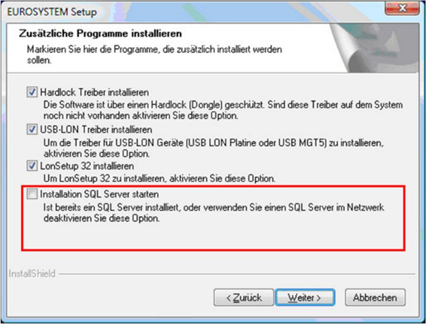
7
1 General safety instructions
1.1 Introduction
Please read these operating instructions carefully before using the soft-
ware. The operating instructions must be kept readily accessible at all
times.
The listed procedures and sequences must be strictly adhered to.
A printed copy of the operating instructions must always be kept at the site
of use.
The relevant regulations regarding accident prevention and health and
safety must be observed.
Personal injuries caused by non-observance of these operating instructions
are not covered by product liability law.
MAHA accepts no liability for damage to the test stand caused by non-ob-
servance of these operating instructions.
Safety instructions warn of dangers and help to avoid personal injury and
damage to property. For your own safety, the safety instructions in this op-
erating manual must be observed.
The applicable national and international safety regulations on occupational
health and safety must be complied with. Each operator is responsible for
complying with the regulations that apply to him and must make his own ef-
forts to comply with the current regulations.
1.2 Symbols and signal words
Denotes important information and notes which indicate easier handling and
operation or warn against incorrect operation.
1.3 Procedure in the event of a malfunction
In the event of any danger, the test stand and its peripheral equipment must
be shut down with the main switch (emergency stop function) on the electri-
cal/switch box.
In the event of any defects, e.g. deformation, leaking liquid or smoke, please
switch off the computer and the test stand immediately and disconnect
them from the mains plug and secure them against further use.
Contact service team.
BAE13101-en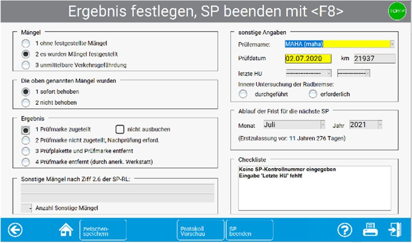
8
1.4 Procedure in the event of an accident
Notify first aiders, the ambulance service and/or immediate care doctor:
o Where did the accident happen (address, workshop ...)?
o What happened?
o How many are injured?
o What injuries have occurred?
o Who is reporting the accident?
Keep calm and answer questions.
1.5 Requirements for operators and service personnel
All persons involved in the operation, assembly, dismantling and disposal of the
equipment must
have the mental and physical capacity for their role,
have read and understood the operating manual, and in particular the in-
structions on the procedure in the event of a malfunction,
show knowledge and experience in handling the equipment and the dangers
posed.
The test stand to be connected may only be put into operation by authorised
qualified personnel. Furthermore, the test stand may only be operated by
instructed qualified personnel.
1.6 Observance of the operating instructions
The operating instructions must always be observed in full. Furthermore, these
must be passed on to any subsequent owners of the system.
1.7 Installation requirements
All passwords and administrator rights are required for installation.
For test lanes with multi-user sections, a TCP/IP network must be available.
For external devices with RS232 connection, an RS232 interface must be
available.
A large number of USB-to-RS232 adapters are available from PC dealers,
but there is no guarantee that every adapter will work on the RS232 inter-
faces. For this reason, MAHA provides adapters via the order number (VZ
910140) that have been tested on MAHA products and have manufacturer
approval.
A LON USB card (VZ 912033) is required to connect the LON test lane to the
computer.
BAE13101-en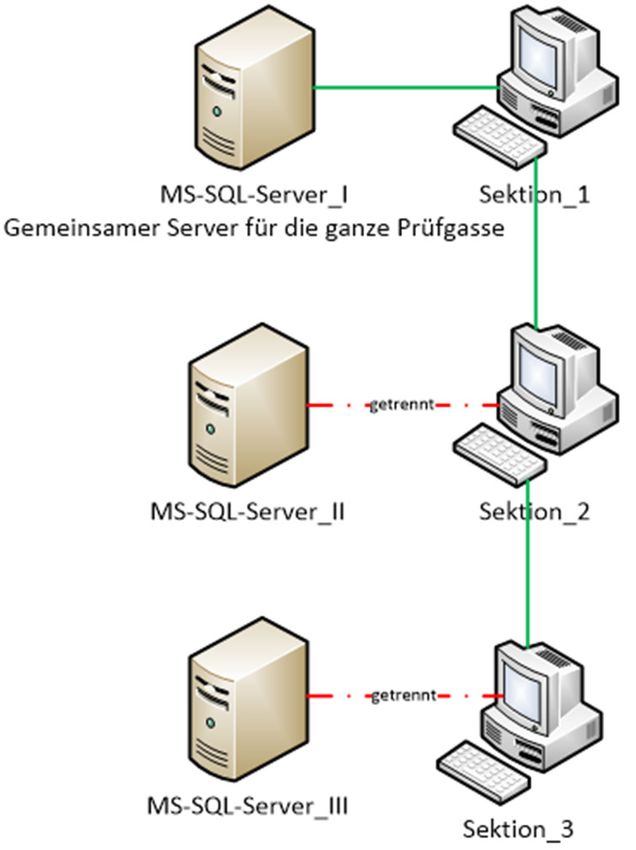
9

2     Installation and configuration

2.1   Start set-up from DVD
      Insert the DVD into the drive. Installa-
      tion will start automatically. If this is
      not the case, please start the or
      by double-clicking.

      To start the installation process please
      click.
      Select the desired set-up language.
      Then confirm with .

      Now the Install-Shield-Wizard appears.
      Confirm with  here as well.

                                                  BAE13101-en
10

              Select the suggested destination direc-
              tory or click  to select a dif-
              ferent directory. Confirm with .

              Select the check boxes of the features
              you want to install.
              Then confirm with .

              Select the check boxes of the features
              you want to install.
              Then confirm with .

              If an SQL server is already installed on your computer, the  option is automatically disabled.

BAE13101-en
11
The V8 and additional selected pro-
grams will now be automatically in-
stalled on your system.
Choose to create an auto-start
shortcut on your desktop and/or run an
automatic node update: Confirm with
.
The option is only available if Lon Setup-32 has been
executed and at least one LON card has been found
Now please select the desired SQL pre-
sets.
Then confirm with .
BAE13101-en12
Depending on the selected preset, additional dialogue boxes may appear.
If this window appears, the installation
has been completed successfully.
Click .
Afterwards the V8 must be started
once as administrator.
To do this, right-click on the V8 icon on
your desktop and select from the context menu
that opens.
The V8 now runs in the administrative context and has the permission to create
the required ODBC data sources for the server. For subsequent EUROSYSTEM
launches, a normal double click on the icon will suffice.
2.2 Software download
The V8 is available for download from
our FTP server on the MAHA homep-
age.
https://www.maha.de/downloads.htm
Differentiation between full versions and service packs.
Full versions are suitable for new installations, for example, since all settings
are reset, and an SQL server is also installed.
BAE13101-en13
Service packs only change e.g. fixed bugs, product improvements or
implemented customer requirements. I.e. all other configured settings will
remain unaffected.
2.3 Unattended set-up
Deployment option:
The installation of the V8 supports what is referred to as an "unattended set-
up". This type of installation is performed without any dialogue boxes appearing
during the installation or any other user input being required.
Unattended set-ups help system administrators to roll out software using "push"
technologies, for example. The user himself can neither cancel the installation
nor influence it in any way.
Generate a response file:
An unattended set-up reads the values of a response file created from the
original user input. To create this response file, run the following call from the
command line:
You must be in the directory where the Setup.exe file is located. Now install
EUROSYSTEM as usual and make all settings that are to be executed later
during an unattended set-up.
After the installation is complete, you will find the Setup.ISS file in the Windows
directory. Copy this Setup.ISS to the source files of your EUROSYSTEM.
Running an unattended set-up:
To run an unattended set-up, run the following call from the command line:
This assumes that the Setup.ISS file is located in the same directory as
Setup.EXE. If the Setup.ISS file is located in a different directory, this can be
specified with the parameter:
BAE13101-en14
2.4 Recommendations and restrictions
If a software deployment tool is being
used, it is recommended that you do
not install the Microsoft SQL server to-
gether with the V8, and instead create
a separate "distribution package" for
this. This is the only way to ensure that
the SQL server installation is not
started a second time.
In case of an unattended set-up, the
item Automatic Node Update must be
deactivated.
Reason: This setting calls the Lon-
Manager 5 tool, which performs an au-
tomatic node update. For security rea-
sons, dialogue boxes are always
shown during this node update, and
these interfere with an unattended set-
up.
BAE13101-en15
3 System requirements
Compatible Microsoft operating systems:
WINDOWS 7
WINDOWS 8
WINDOWS 8.1
WINDOWS 10 release < 2004/H2
Hardware
CPU HD space RAM USB ports RS 232
2 GHz 20 GB 2 GB 4 optional
Compatible SQL server
2014
2016
Note:
MAHA uses an SQL express version in the V8. That means this version is
license-free for the customer per se, but has the following restrictions.
Max. 10 GB storage capacity
Use of only one CPU
Use of the main memory (RAM) is fixed at 1GB
BAE13101-en16
4 Licensing
4.1 Test period
The software is license-free for 30
days after installation and can be used
as a full trial version.
After the 30 days, the software must
be licensed and is then available for an
unlimited period of time.
4.2 Activation
A PIN is required to activate the soft-
ware and its options.
This is a ten-digit number and includes
the version as well as the selected op-
tions.
If you do not have a PIN, you can obtain one from the following service address:
MAHA Service Center
Hoyen 20
87490 Haldenwang
Phone: +49 8374 585 100
Internet: http://www.maha.de
Mail service@mahaservicecenter.com
or at:
https://www.maha.de/de/software/activation-code
To get the 32-digit activation code please press the
button in the page navigation toolbar. You will now be redirected to the
following page:
Now select the appropriate product and fill in the required fields.
BAE13101-en17
Use the copy function to easily copy the company code and com-
puter ID from the software interface.
Then confirm with .
Now enter your e-mail address and
PIN:
Then confirm with .
You will immediately receive the 32-
digit activation code. In addition, you
will receive a copy sent to the e-mail
address we have on file for you.
Now copy the activation code and
paste it into the interface.
BAE13101-en18
Then confirm with . (Com-
puter ID corresponds to MAC address).
5 Operation
5.1 Main menu and screen elements
Note:
The operation of the V8 software is menu-driven and largely self-explanatory
and intuitive. In the following, only the most important program items are
explained.
Status bar/Operator guidance
Start new test
Settings
Technician menu Redisplay measure-
Administration ment values
Diagnostics Quit or restart program
Burger menu for extended
menu navigation
In general, all functions or buttons on the screens can be selected using the
cursor or tab key and selected with or .
You can also select by clicking the mouse or by touching the buttons via touch
screen.
The screen layout of the main menu may differ slightly depending on the sec-
tion number and/or the settings, browser or options selected.
BAE13101-en19
Screen elements
Information line
Input fields
Buttons
Yellow = mandatory fields
Information line
The first line of the screen is the information line. The notices seen here during
the program run refer to the next step and/or the current program activity.
Input fields
Input fields appear recessed on the screen. Entries can be made via the
keyboard. You can switch between the input fields by pressing the tab key (or
cursor keys up/down, or the return key).
Within an input field you move with the cursor keys right/left. Overwrite mode is
enabled, i.e. the input of a character overwrites the character to the right of the
cursor. Overwrite mode can be deactivated by pressing the Ins key.
Characters before the cursor can be deleted individually by the Del key (those
behind the cursor using Backspace).
Buttons
Buttons appear highlighted like a physical button on the screen. In general,
buttons can be activated by mouse click and by pressing the corresponding
function key on the keyboard.
Touch-screen monitors offer additional operating options and convenience.
Not all buttons shown here are always visible on the screen. Their position also
changes depending on the type of display. For example, other buttons are larger
and labelled. Their function is thus evident from the label or the symbol.
BAE13101-en20
Button Assignment
Previous page
Next page
Main menu
One level up
One level down
Call up test report/start printout
Exit page
5.2 Start and end program
Start program
Turn the test stand's main switch to "ON".
Start Windows and start the V8 with a double click on the desktop icon.
The first screen to appear is the MAHA logo. In the bottom line you can read
which version of the program it is.
Initialisation. Please wait.
The components listed under are installed and ready for
operation.
Confirm with .
appears and then the main menu of the user software appears
BAE13101-en21
End program
Before switching off the main switch, the software and the Windows operating
system must be properly exited.
From the main menu, press .
A window will now open above the main screen
To exit the program, select:
to return to the program
to exit the program
5.3 Virtual remote control
This is required when using a tablet to enter customer or vehicle data if no
keyboard is connected.
Under the soft dips , set no.
35 to active.
1 To call up the virtual remote con-
trol, click on this symbol in the in-
formation line.
The following view then opens:
2 To switch off or put the remote control in the background, click the icon
again.
BAE13101-en22
6 Test procedure
6.1 Side slip test
1 Drive the front axle of the vehicle over the test plate (speed between 2.5 and
7.5 km/h) of the side slip tester.
Side slip tester active
This screen appears and displays the
track deviation measured for the front
axle in m/km.
2 If the measured values are within the tolerance range, i.e. if the side slip test
is OK, the values are displayed in green (side slip test faulty in red).
3 The rear side slip is measured when the rear axle of the vehicle is moved
over the side slip tester.
The rear axle is tested in the same way as the front axle.
Side slip tester active
The measured values are now added to the screen.
In the example, the measured values
are outside the tolerance range, i.e. the
side slip test is faulty.
The first measured value stored in the temporary memory is always the value
for the side slip of the front axle. This order cannot be altered.
Intervention by the tester in the automatic test sequence is not possible with
this measurement. When the test is repeated, the measured values in the tem-
porary memory are overwritten.
The measured values can be saved and displayed again later. Please read the
detailed description in the chapter "Saving the measurement" and "Displaying
measurements again".
BAE13101-en23
6.2 Shock absorber test
1 Park the vehicle with the front axle on the test plates. The wheels must be
straight and centred on the test plates and must not be blocked by the
gears or an applied brake.
The test stand is automatically activated when both test plates are
loaded with > 100 kg.
The test is carried out in a controlled manner from 10...5 Hz and is
performed simultaneously for both sides.
After completion of the measurement, the test stand switches off
automatically.
The degree of damping D is determined and displayed on the screen.
2 Drive the vehicle until the rear axle is on the test plates.
The test is carried out in the same way as for the front axle
The button shows the amplitudes are ei-
ther separately or one superimposed on the other.
You can intervene in the automatic test sequence by moving onto the test
plates again. Check if the field in the top centre shows the desired axle, if
necessary, switch to the correct axle with the navigation keys.
BAE13101-en24
6.3 Brake test
It is not necessary to carry out the brake test to prove the legally specified brak-
ing effect up to the slip cut-off.
The slip cut-off is generally to be understood as a safety cut-off (gentle on the
tyres) and not as a cut-off point for the brake test. *
Stopping the brake test prematurely at approx. 90 % of the possible braking
force is completely sufficient and is strongly recommended to avoid tyre dam-
age!
* Please observe the implementation regulations for determining the braking ef-
fect.
The specified sequence of brake tests is (example truck):
1 Ovality test of the front axle
2 Brake efficiency test of the front axle
3 Brake efficiency test of the parking brake
4 Ovality test of the rear axle
5 Brake efficiency test of the rear axle
The acquired measurement values are stored in this order the temporary
memory. The test stand does not automatically detect which brake you are cur-
rently testing.
For example, you have performed the brake test for the parking brake. The dis-
play jumps to the next brake test, i.e. for the rear axle. Even if you now repeat
the parking brake test, the measured values are still stored as rear axle values.
Always pay attention to the indicated brake to be tested – front axle or rear
axle. If necessary, use the function keys to switch to the desired axle.
Intervention in the automatic test sequence and the correct method for storing
data are described after the ovality test and the brake efficiency test.
Drive slowly and straight into the roller set. Both sensing rollers must be de-
pressed. Move the gearbox to the zero position and release the brake.
BAE13101-en25
6.3.1 Ovality test
1 In the field in the middle, appears for front axle
2 A yellow sector for the ovality measurement is shown in the analogue
displays
3 Now brake slowly until the braking force is in the yellow ranges and hold it
there.
4 Now wait until the timer has run out. The ovality values are stored in the
temporary memory.
The settings for the braking range of the ovality measurement and the timer are
predefined. The timer runs out in a period corresponding to one wheel
revolution. Changes to these settings may only be made by the MAHA Service
Center. The brake efficiency test is carried out directly after the ovality test.
6.3.2 Brake efficiency test
5 Depress the brake pedal slowly until about 90 % of the possible braking
force has been achieved. Braking until the slip cut-off is not necessary.
6 The motors will now stop. The measured maximum braking force appears
on the display and is stored in the temporary memory too. The
corresponding button now appears in green.
7 Release the brake pedal immediately. The test stand is now ready for the
next test and the motors start up again.
8 With the motor running, drive the vehicle to be tested forwards out of the
roller set.
BAE13101-en26
(Automatic mode active)
After the ovality and brake efficiency test of the front axle, the side slip test
and the shock absorber test of the rear axle are carried out. Then drive the rear
axle into the roller set of the test stand.
Then the brake efficiency test for the parking brake is performed. This
runs in the same way as the brake efficiency test of the front axle. Follow steps
5 and 6. Finally, ovality and brake efficiency tests are performed for the rear
axle . The procedure is the same as that of the tests on the front axle.
Follow steps 1 to 7.
6.4 Leaving the test lane or the test stand
The automatic test sequence is now complete. The display returns to the main
menu.
9 Please wait until the motors of the test stand have switched off.
10 If possible, exit the test lane forwards, otherwise quickly drive over the roller
set of the test stand and the test plates of the shock absorber test stand
and the side slip tester in reverse.
BAE13101-en27
(Manual mode active)
11 Save the measured values. Description in the section "Saving the
measurement".
6.5 Intervention in the automatic test sequence
Enter the test stand slowly and straight with the axle to be tested again. Both
sensing rollers must be depressed. Set the gearbox to the zero position and
release the brake.
1 Select the, , (or ) buttons to switch between the front
axle, rear axle or parking brake displays.
2 The field in the middle shows which brake you can repeat the test for.
3 The ovality test is repeated with . Wait until the timer has run out.
4 Press to delete the temporary memory.
5 sets the displayed measured value as the max. measured value if,
for example, the vehicle does not reach the specified slip.
6 stores the displayed measurement value for the brake that is
displayed in the temporary memory.
BAE13101-en28
Changing measured values in the way described above can only be done as
long as the measured values are still available in the temporary memory.
If the measurements have already been saved with customer and vehicle data
after the test procedure (see section "Saving the measurement"), subsequent
changes are no longer possible. In this case, run the test again.
7 Perform visual inspection
7.1 Entering and saving visual defects
The inclusion of visual defects in the assessment of a vehicle is at the
discretion of the user. The entry can be made before or after the test sequence.
Even if the measured values are displayed again, it is still possible to enter
defects.
EUROSYSTEM's catalogue of defects corresponds to the assessment catalogue
for the vehicle roadworthiness test as defined under §29 of the German Road
Traffic Licensing Act (StVZO).
From the burger menu on the start
page, select .
1 An assessment catalogue now ap-
pears.
Defect category
BAE13101-en29
2 Select the defect category.
Subdivisions of the defect category
then appear (here, for example,
"brake system"):
Select defect
3 Select the defect.
This is followed by the screen for
determining the location and evalu-
ating the defect (next screen).
If defect groups consist of several
pages, you can scroll through them
using Page down or Page up.
After performing steps 1 to 3, the
screen shown below appears.
Specify the location and assess-
ment of the defect
4 Select the location of the defect.
The blue dot at the bottom right of
the respective button turns red (de-
fect selected). By pressing the but-
ton again, the marking can be
"switched off" again.
5 Now assess the defect(s). After selection and an exact determination of the
defect, it must be saved with, otherwise your entries will be
lost.
6 With the button it is possible to link individual comments
to the defect.
7 An input window appears in which additional comments of max. 40
characters in length can be entered.
8 Press to accept the entry
9 After accepting the defect and the comments, the display automatically
returns to the screen with the defect categories. You can now create further
defects using the procedure described.
10 Enter all other defects in the manner described.
BAE13101-en30
7.2 Displaying the listed defects
1 To display the overview, press the
button in the
toolbar
2 It is also possible to make or
change notes and comments later
in the overview.
3 To do this, select the desired de-
fect so that it is highlighted.
8 Save measurement
To save the entire measurement, a corresponding customer with vehicle must
be assigned. The stored measurement results are managed in the
measurement database. From this database the measurements can be
displayed again at any time.
A customer or vehicle can be assigned and linked before or after an inspection.
The measurement database also includes customers who are in a queue for
testing. Customers are added to the queue using .
After the automatic test sequence has been completed, the main menu
reappears on the screen. Proceed as follows:
Measured values available (save)
You have already left the test lane for this purpose.
BAE13101-en31
1 Please select . Where a
vehicle has been assigned before
the start of the test, select in the burger
menu. A selection from the measu-
rement database now appears:
2 Via touch display or interaction with the mouse, the corresponding vehicle
can now be assigned. It is also possible to filter the database with a search
term/attribute (e.g. indicator) in the top line.
3 Confirm with . Depending on the assignment of the vehicle
before or after the test, the following now happens:
8.1 Assignment after the test
The screen confirms that the acquired
measured values are stored as a data
record with the assigned customer/ve-
hicle. This coincides with the comple-
tion of the vehicle inspection, i.e. when
the screen returns to the main menu
after approx. three seconds, the sys-
tem is ready for a new measurement.
8.2 Assignment before the test
You have selected a vehicle from the queue (open list) to start testing now.
1 The main menu appears and displays the vehicle registration number. The
system is now ready to acquire the measured values for the active vehicle.
The operator guidance now sig-
nals: "Vehicle inspection can begin
..." The test lane or test stand can
now be driven onto.
2 After the vehicle test has been completed, the operator guidance system
displays the following message:
Measured values available (save) ...
3 The operator now has two options:
BAE13101-en32
a Perform further tests with the active vehicle.
b Save the measured values with and end the vehicle test.
8.3 Prepare new vehicle inspection
Before starting a new test sequence, please ensure that the temporary memory
is empty and that the message "Ready for test" is displayed in the operator
guidance
After the test values have been saved correctly, test standby mode
automatically reappears in the operator guidance. However, a message other
than the ready message may also be signalled in the operator guidance, or that
a test is to be aborted and started from the beginning.
1 To do this, please press the button in the main menu
9 Customer and vehicle management
In customer and vehicle management, stored customer and vehicle data can be
organised. A customer is stored as a data record in connection with a specific
vehicle registration number.
Once customers have been saved, they can be called up again and again in
order to assign measured values from tests that have been carried out to them.
In this way, for example, tests carried out at different times can be compared.
9.1 File specification
You can switch between the input fields with the cursor key or the return key if
no touch screen is used. Data entry is restricted to numeric or alphanumeric
entries for individual fields.
1 To do this, select
from the main menu using the but-
ton. The following screen appears.
BAE13101-en33
2 When entering the data, the mandatory fields shown in yellow must be filled
in. The customer is free to fill in the remaining fields.
If the coloured mandatory fields
are not filled, this error message
appears:
9.2 Load master data
To simplify data entry, existing data records can also be loaded into the input
window:
retrieves an existing customer and the customer data-
base appears.
assigns a vehicle to the customer and the vehicle database
appears.
loads a complete dataset. Here vehicle and owner
data incl. all measured values.
With , a past measurement is
loaded. Here incl. all vehicle and owner data, but without measured values.
9.3 Complete data entry
After completing the data entry, the following options are available:
With , the upcoming vehicle inspection can be started
immediately. The system immediately switches to the main menu. The op-
erator guidance reports "Vehicle inspection can begin..."
saves the record to the server. The input window is cleared and
a new vehicle can be created.
With , the data currently listed can be changed or
corrected.
With , all listed inputs and data are discarded.
BAE13101-en34
9.4 Delete measurements
See section "Administration / Database (Administrator)".
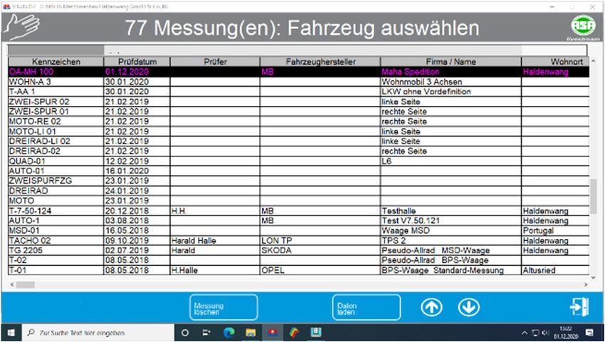
9.5 Redisplay measurements
When redisplaying measurements, the following distinction must be made:
Display of a currently performed measurement, i.e. the corresponding cus-
tomer/vehicle is still active.
Display of a measurement whose acquisition has already taken place some
time ago, i.e. the desired measurement must first be loaded.
1 From the main menu, select .
The measurement database ap-
pears from which the desired
measurement is selected:
Select the vehicle to be examined, then the screen from b.) appears
b Once a test has been performed,
the overview of all measurements
performed appears immediately:
2 Select the desired piece of testing equipment. If the test was passed, the
buttons appear with a green frame, otherwise with a red frame.
BAE13101-en35
10 Brake test
Although the following illustrations only ever show values recorded for a front
axle, the description of the brake test re-display procedure applies equally to the
parking brake and rear axle.
1 Select the button.
2 Here you can choose between the
front axle, the parking brake or the
rear axle to visualise the respective
measured values.
3 Likewise, a diagnostic log can be opened in the respective display. This is
done by pressing the printer symbol.
4 You can then navigate through the
individual axles in the respective
graphical axle evaluation.
5 Furthermore, various graphs are of-
fered in the individual view for de-
tailed visualisation.
6 The example shows .
Here the braking force is shown left over right. The values are given on the right
in kN and their difference can be read in per cent.
BAE13101-en36
The curve should be within the bound-
ary lines (corridor). The corridor can be
changed in the variable list.
The following buttons are available for the graphic displays:
Choose graph
Show / hide application pressure
Show / hide guides
Show / hide legend
Constant (maximum) scaling
Smooth curves
Show graph whole page / show measured values
Change background colour of the diagram
Change line thickness
BAE13101-en37
10.1 Final evaluation of brake test
10.1.1 Total weight has already been recorded
All braking values and the resulting de-
celeration are displayed.
10.1.2 Total weight was not recorded
For example, the brake test was the only test carried out on a plate brake tester
without drive-over scales.
1 The following screen appears. This
shows only the measured braking
forces, but this display is supple-
mented by the button.
2 When the button is
pressed, the display changes to the
weight input screen.
3 Now enter a weight in kg (see vehicle registration document) and confirm
the entry. Subsequently, the final evaluation is issued in relation to the
weight.
Alternatively, you can also dispense with entering the weights. The final
evaluation will then appear without the percentage deceleration.
BAE13101-en38
11 Shock absorber test
1 Select
2 You can switch between the front
and rear axle displays using the
cursor or return key if you are not
using a touchscreen.
The test stand measures the overall axle damping, not the quality of the shock
absorbers. The manufacturer shall not be liable for any costs or damage in-
curred as a result of the incorrect assessment of shock absorbers.
12 Side slip test
Select to display the side slip tester test values again.
The display for the side slip test ap-
pears, the results of which are already
known from the test procedure. Meas-
ured values outside of the specified
limit values are displayed in red.
BAE13101-en39
13 Test without predefinition
To start the test sequence, the monitor must show the main menu. The test
lane is now ready to be driven onto.
1 After moving onto the roller set, ac-
tivate the pointer stop with on
the FFB 3. (Only 1x per vehicle re-
quired.)
2 Apply the brake when prompted.
The max. measured values are dis-
played.
3 Enter the axle number and brake
type, press the button on the
remote control to save the meas-
urement.
Measured values are stored
4 If necessary, change the axle and repeat the procedure for other brakes.
5 Exit roller set
BAE13101-en40
6 Press the button to
open the Vehicle/owner data
screen.
7 Enter data (mandatory fields are
highlighted in yellow), then confirm
with → or press .
The newly created vehicle appears
on the main screen.
8 The button on the main
screen can be used to open the
measured values overview.
Brake evaluation: Individual measured
values can be selected and displayed.
The printer icon can be used to open
the printer menu for printing the re-
sults.
BAE13101-en41
In the main menu press the button
, then an intermediate
query will appear asking you how you
wish to save.
9a The button in the pop-
up window is used to cache the
measurement. The vehicle is then
visible in the open list, and the
measured values can be changed
again later.
9b The button in the pop-up window finished and saves the
measurement. The vehicle is removed from the open waiting list, and the
measured values can no longer be changed.
With button
in the burger menu, the vehicle can
later be selected from the list, retested
and the previous measured values
overwritten.
14 Safety inspection
1 In the burger menu, navigate to the
item and
confirm this.
2 Select here
BAE13101-en42
3 Then select the desired test se-
quence .
4 Enter data or load vehicle accordingly.
5 Subject vehicle to inspection and
note defects as appropriate.
6 Finally, determine the result of the safety inspection and conclude it.
Changes are not possible after that.
15 Define automatic measurement
1 In the burger menu, navigate to the item and
confirm this
2 Select here
BAE13101-en43
3 Define vehicle manually or load
definition.
4 Move to test stand, perform in-
spection.
5 After completion of the inspection,
the measured values can be cor-
rected or the vehicle can be termi-
nated.
BAE13101-en44
16 Administration
Only functions that apply to users without extended access rights are described
below.
1 Under Options, Settings and Ad-
ministration, activate the menu
item
16.1 Database (Administrator)
The menu
item can be used to delete measure-
ments and open tests and to save, ex-
port and import data.
The following options are available for database maintenance:
Delete individually
Delete via date range
Delete via IDs
Delete open tests
Backup
Restore
Transfer data from external EDP
Table export / import / delete
Change settings
Save settings
Compress database
BAE13101-en45
16.2 Delete measurements individually
1 In the database menu, select
2 Mark the measurement to be de-
leted in the table
3 Then select
Before deleting the data record, a
confirmation prompt appears:
4 Select to delete the measurement or exit the screen with if you
do not want to delete the record.
After deletion, the database admin-
istration screen appears again:
16.3 Delete measurements via date range
1 In the database menu, select
2 Enter the desired period for which
measurements are to be deleted in
the two input fields.
3 Select to delete the measurements or exit the screen with if you
do not want to delete.
After deletion, the database administration screen appears again.
BAE13101-en46
16.4 Delete measurements via ID number range
1 In the database menu, select
2 Enter the desired ID number range
for which measurements are to be
deleted in the two input fields.
3 Select to delete the measurements or exit the screen with if you
do not want to delete.
After deletion, the database administration screen appears again.
16.5 Delete all open tests
1 In the database menu, select
2 Select to delete open tests or
exit the screen using if you
do not want to delete.
After deletion, the database admin-
istration screen appears again.
16.6 Backup of the database
1 In the database menu, select
2 Select to create a backup in
the suggested directory, or use
to select the backup file it-
self. Alternatively, exit the screen
with if you do not want to
create a backup at all.
After the backup, the database administration screen appears again.
BAE13101-en47
16.7 Restoring the databases
1 In the database menu, select
2 Select to overwrite all data-
bases with the backup file, or exit
the screen with if you do not
want to perform a restore.
After the restore, the database administration screen appears again.
16.8 Transfer data from an external EDP
1 In the database menu, select
The files are automatically trans-
ferred from the third-party EDP.
The number of data records read in
is displayed.
After the data transfer, the data-
base administration screen ap-
pears again.
16.9 Table export / import / delete
1 In the database menu, select .
2 Select the desired tables and then
or or .
3 Confirm the corresponding confir-
mation prompt.
BAE13101-en48
16.10 Test equipment (QA representative)
Via the menu item , the test equipment and the calibration
periods can be displayed, changed and printed out.
1 Select administration menu
The following screen appears:
2 Enter the test equipment. Entering the test equipment name is mandatory,
all other input fields are optional.
3 allows test equipment data which has already been
created to be loaded.
4 adopts the manufacturer's specifications.
5 With , a work order can be created for the test equipment.
6 Press to open this menu
and select a menu item.
16.11 Old measurements
Any measurements from the measurement database can be selected and
loaded via the menu item "Old measurements".
1 Select menu item .
The following screen appears:
2 Mark the desired measurement in the list
3 Select
BAE13101-en49
16.12 Export measurements
1 Select menu item .
The following screen appears:
2 Now mark the desired measurement in the list here
3 Then select
4 Select the desired export directory
in the file search field and confirm
with
16.13 Import measurements
1 Select menu item
Select the desired import file in the file search field and confirm
with .
The file is transferred to the measurement database
BAE13101-en50
16.14 Customer master data
1 Select menu item .
The following screen appears:
2 Enter the customer data. The coloured fields must be filled in.
3 Use to open the pop-up
menu and select a menu item.
16.15 Vehicle master data
1 Select menu item
The following screen appears:
2 Enter the vehicle data. The fields with a coloured background must be filled
in
3 Use to open the pop-up
menu and select a menu item.
BAE13101-en51
16.16 Complete vehicle master data
1 Select menu item
The following screen appears:
2 Enter the customer and vehicle data. The fields with a coloured background
must be filled in
3 Use to open the pop-up
menu and select a menu item.
17 User
The supervisor can be created as the administrator. This user in turn can create
other users and assign rights.
1 Select menu item
The following screen appears:
2 Please enter a username.
3 Check one of the boxes according to the user's field of application.
BAE13101-en52
4 Fill in the additional input fields.
5 Use to open the pop-up
menu and select a menu item.
18 Settings
Please note that improper modifications may cause functional errors that are
not covered by the warranty.
The functions of the menu are nevertheless accessible to the user, but should
only be activated under professional instruction. It is conceivable that medium
and small malfunctions can be remedied by remote maintenance via Team-
Viewer through our Service Center +49 8374 585 100.
In addition to the system settings, software adjustments for test stands and
measuring devices subsequently integrated into the test lane can be carried out
here too. The user can also select the language and choose an interface design.
1 Starting from the main menu, navi-
gate to
2 Select
BAE13101-en53
3 The setting menu now appears.
19 Diagnostics
The diagnostics menu provides all program and system information. The
connected devices can be checked for proper functioning.
1 Starting from the main menu, navigate to
2 Now select the
The diagnosis menu appears:
20 Print all settings
1 Select menu item
2 Select the desired category and
start the printout.
BAE13101-en54
21 Version control
1 Select menu item .
The configuration is checked to en-
sure it is up to date by comparing
actual and target versions and
evaluated accordingly.
22 PC system overview
1 Select menu item
An overview of all technical data of the
computer used appears:
23 Process protocol
1 Select menu item
2 The screen can be exited again with without changing the existing
settings.
BAE13101-en55
24 LON bus system
1 Select menu item
The first cycle queries the versions of the individual components. In the third
column, the version numbers are displayed one after the other.
The subsequent cycles query the readiness of the components.
In the first column the readiness is dis-
played with "OK" or "Not OK".
2 Press to end the query and return to the diagnostics menu.
25 SQL database
1 Select menu item
An information window about the SQL
database appears.
2 Confirm with .
3 The screen can be exited again with .
BAE13101-en56
26 Remote control and pedal force
1 Select menu item .
2 The remote control and/or the pe-
dal force meter can now be
checked here.
27 Scale
1 Select menu item .
2 The scale can be tested with a test
weight.
BAE13101-en57
28 Check RPM pulses
1 Select menu item .
2 The speed can be checked here.
29 Check pit safety system
1 Select menu item
2 The pit safety can be checked with
.
BAE13101-en58
30 Calibration
1 Select menu item
2 Select the testing equipment to be
calibrated.
Example: Calibration of the braking
forces.
31 Pointer
1 Select menu item
2 Mechanics and hardware can be
tested here (access only with in-
staller rights).
BAE13101-en59
32 Additional tests
32.1 Noise detection
The noise detection option can be enabled via the software
(option #8).
Select noise detection
Start motors
In the navigation menu each motor can
be individually started and switched
off.
BAE13101-en60
Change frequency
Press or to reduce or in-
crease the frequency of the test plates.
With one side can be set for
modification.
Save noise points
After setting the frequency, the sound
point can be stored with .
A list of the saved noise points is dis-
played.
Automatic shutdown
To protect against overheating, the
motors are automatically switched off
after a set running time.
This message is displayed to the
tester for confirmation in the event
of overheating.
Weighing mode
Select from the
burger menu.
BAE13101-en61
The following dialogue box will now ap-
pear:
Here you can now choose between the different test modes.
The left and right weights and the total axle weight are displayed.
Pit safety system
If the brake tester is in operation, the pit safety device secures the entire pit or
the safety area around the test stand. If a person, an object or a movement is
registered here, the test stand is switched off by the pit safety system.
If the pit safety device has been triggered in the drive state, it must be unlocked
after removing the trigger object. To do this, press the button on the console
housing.
32.2 Load simulation
Pull-down device with proportional valve
The pull-down device is activated on the measuring screen after driving onto the
roller set.
1 Drive onto the test stand. The weight and rolling resistance are displayed.
The display then changes to the measurement screen.
2 Activate the pull-down mode via the icon be-
low.
BAE13101-enYou can also read