Frank Kitts Carpark DSA Detailed Seismic Assessment - Detailed Seismic Assessment Report
←
→
Page content transcription
If your browser does not render page correctly, please read the page content below

Frank Kitts Carpark DSA
Detailed Seismic Assessment
                              Frank Kitts Carpark
                                 15 Jervois Quay
                                      Wellington

       Detailed Seismic Assessment Report

                                     Revision 5
                              11 December 2020
                                      105978.19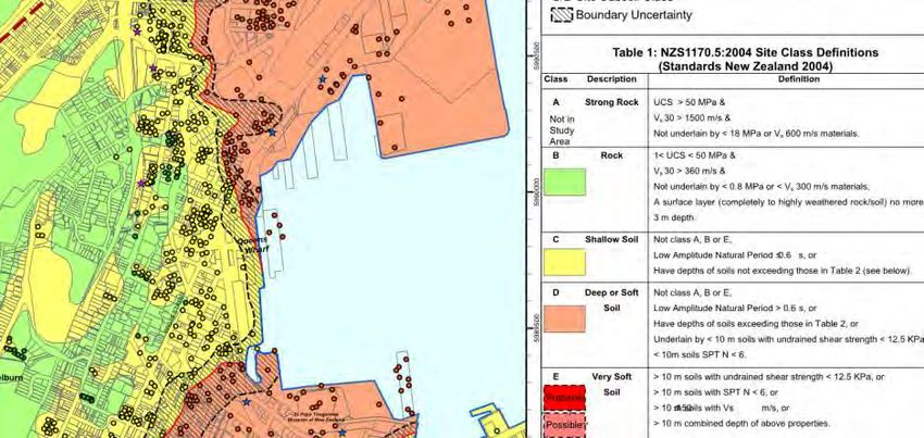
Level 2, Chartered Accountants House, 50 Customhouse Quay
                                                                                                         PO Box 942
                                                                                                     Wellington 6140
                                                                                               holmesconsulting.co.nz

Detailed Seismic Assessment Report
Frank Kitts Carpark DSA

Prepared For:
Wellington City Council

Date:                  11 December 2020
Project No:            105978.19
Revision No:           5

Prepared by:                                            Prepared by:

May Teoh                                                Rolf Veldboom
GRADUATE ENGINEER                                       DESIGN ENGINEER
Holmes Consulting LP                                    Holmes Consulting LP

Reviewed by:                                            Reviewed and Approved by:

Panos Armaos                                            Ian Hills
SENIOR PROJECT ENGINEER                                 PROJECT DIRECTOR
Holmes Consulting LP                                    Holmes Consulting LP

 105978.19DSA2211.002.docx

                Australia Netherlands New Zealand USA
Report Issue Register
       DATE             REV. NO.                               REASON FOR ISSUE
     8 / 11 / 19           0       DRAFT - For internal communication
     22 /11 / 19           1       DRAFT - For internal review
     6 / 12 / 19           2       DRAFT - For client review
     3/2/2020              3       Issued to Client
    24/2/2020              4       FINAL – Minor update for submission to local authority
                                   FINAL – reissued to include appendix B (omitted in rev 4) and to correct
    11/12/2020             5
                                   Table 1.

                                                                      Frank Kitts Carpark DSA      Revision 5
                                                                                     105978.19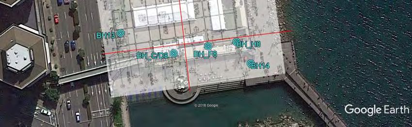
CONTENTS
Executive summary ............................................................................................................................... 1
Background ........................................................................................................................................... 1
Building description .............................................................................................................................. 1
Assessed seismic rating ........................................................................................................................ 1
Engineering assessment summary report ............................................................................................ 2
1          Introduction and background ........................................................................................... 3
2          Scope ................................................................................................................................. 3
3          Terminology and key definitions ....................................................................................... 4
4          Building description .......................................................................................................... 5
4.1        Gravity load resisting system ........................................................................................... 5
4.2        Earthquake (lateral load) resisting system ....................................................................... 6
4.3        Foundations and subsoil ................................................................................................... 6
5          Assessed seismic rating .................................................................................................... 7
5.1        Identified Structural Weaknesses ..................................................................................... 8
5.2        Secondary structural and non-structural elements .......................................................... 9
5.3        Commentary on structural weaknesses ........................................................................... 9
6          Basis of this report ........................................................................................................... 14
6.1        Information available for the assessment ........................................................................ 14
6.2        Site observations and investigations ............................................................................... 14
6.3        Earthquake demand used in the assessment ...................................................................15
7          Method of assessment ......................................................................................................15
8          Statutory requirements for existing buildings ................................................................. 16
8.1        Requirements under the Building Act 2004 (as amended by the Earthquake-prone
Buildings Amendment Act 2016) .......................................................................................................... 16
9          Limitations ........................................................................................................................ 18
10         References ........................................................................................................................ 19

Appendix A Engineering assessment summary report ...........................................................................
Appendix B Geotechnical Assessment Report .......................................................................................
Appendix C Technical Summary of Equivalent Linear Static Analysis and Evaluation...........................

                                                                                                      Frank Kitts Carpark DSA             Revision 5
                                                                                                                     105978.19
TABLES
Table 1 – Structural weaknesses ............................................................................................................ 1
Table 2: Grading system for earthquake risks relative to a new building ........................................... 7
Table 3 - Structural Weaknesses identified in the DSA ........................................................................ 8
Table 4 - Secondary structural and non-structural elements .............................................................. 9
Table 5 - Comparison of parameters used to determine the seismic coefficient between
NZS4203:1984 and NZS1170.5 .............................................................................................................. 10
Table 6 - Material strengths used in assessment ............................................................................. C-2
Table 7 - Floor seismic weight summary ........................................................................................... C-2
Table 8 - Seismic coefficient parameters for NZS4203:1984 and NZS1170.5:2004 ........................... C-4
Table 9 - Considerations for loss of seating ......................................................................................C-7
Table 10 - Precast wall panel in-plane flexure ................................................................................. C-10
Table 11 - Precast wall panel concurrent loading flexure ................................................................ C-13
Table 12 - Secondary structural and non-structural elements ....................................................... C-20
Table 13 - Seismic rating of potential structural weaknesses ........................................................ C-26

                                                                                               Frank Kitts Carpark DSA           Revision 5
                                                                                                              105978.19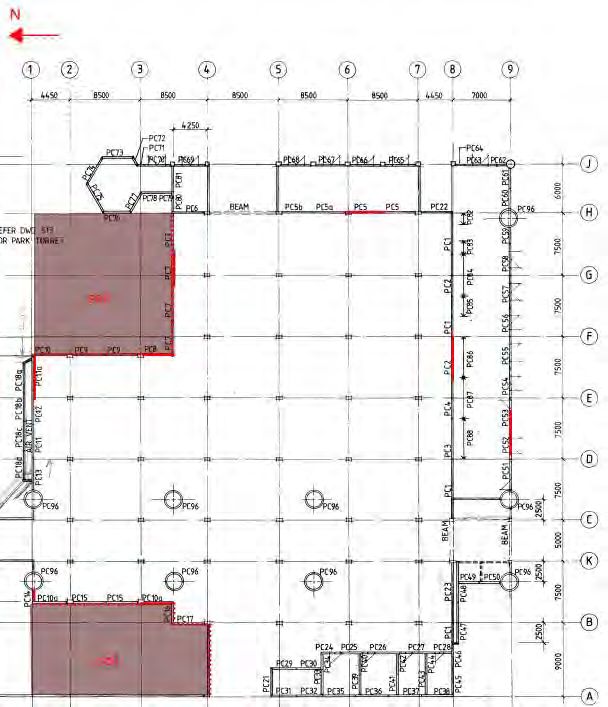
FIGURES
Figure 1 – Extract from Google Maps – Frank Kitts Carpark location ................................................... 5
Figure 2 - Seismic spectra comparison between NZS4203:1984 and NZS1170.5:2004 ........................ 10
Figure 3 - Illustration of pile behaviour under liquefaction scenarios ................................................ 13
Figure 4 - Section through long direction .......................................................................................... C-1
Figure 5 - Seismic spectra comparison between NZS4203:1984 and NZS1170.5:2004 ..................... C-4
Figure 6 – Extract from as-built drawing S8 and S16 - diaphragm to wall connection ..................... C-6
Figure 7 - Double tee units support – extracted from drawing S2 of the as-built drawings ............. C-6
Figure 8 – Double tee support conditions – (Left) double-tee units positioned directly against the
beam and (right) initial spalling at the back of the double-tee unit .................................................C-7
Figure 9 – Extract of the as-built drawing S7 - showing the precast concrete wall panels around the
perimeter of the structure ................................................................................................................ C-8
Figure 10 – Extract from the as-built drawingS7 - showing the connection between precast concrete
wall panel and footing...................................................................................................................... C-9
Figure 11 – Extract from the as-built drawing S7 - showing the precast concrete wall panels in
section ............................................................................................................................................. C-10
Figure 12 – Building response curve of the precast concrete walls in the East-West direction ....... C-11
Figure 13 - Extract from Wood and Elms showing earthquake pressure on rigid wall..................... C-12
Figure 14 – Extract from as-built drawing - plan of precast concrete frame with foundation; extent of
beam of frame ................................................................................................................................. C-14
Figure 15 – Extract from as-built drawing S2 - showing beam-column seating detail ..................... C-14
Figure 16 – Extract from as-built drawing S2 - showing beam-wall seating detail .......................... C-15
Figure 17 - Extract from as-built drawing S6 - showing column reinforcement detail ..................... C-15
Figure 18 – Extract from Microstran model - showing gridline 6 precast concrete frame model .... C-16
Figure 19 – Extract from as-built drawings – showing foundation beams and pile caps ................. C-17
Figure 20 - Illustration of pile behaviour under liquefaction scenarios where:............................... C-19
Figure 21 - Extract from as-built drawing A1 and S10 – location and plan of look-out tower ...........C-22
Figure 22 - Extract from as-built drawing S30 – look-out tower connection to the rest of the structure
.........................................................................................................................................................C-22
Figure 23 - Extract from as built drawing S4 - showing typical wall cap types and connection detail
between the wall cap and precast concrete wall panel ................................................................ C-23
Figure 24 - Extract from as-built drawing - showing the reinforcement detail of precast concrete
wall panel and start bar connection to the footing ........................................................................ C-24

                                                                                                          Frank Kitts Carpark DSA              Revision 5
                                                                                                                         105978.19
EXECUTIVE SUMMARY
Background
Holmes Consulting LP have been engaged by Wellington City Council to complete a Detailed Seismic
Assessment (DSA) of Frank Kitts Carpark, at Jervois Quay, Wellington. The DSA has been completed in
accordance with “The Seismic Assessment of Existing Buildings, Technical Guidelines for Engineering
Assessments, July 2017, Version 1” (NZSEE, 2017), referred to as the “Engineering Assessment Guidelines”
within this report.

Building description
The carpark is a single storey building. The building was designed and constructed in 1989. Its main
purpose is to function as a carpark building where the roof is used as a public park. However, it is
nowadays also used for to hold weekend markets and festival events.

The floor plan of the carpark comprises No.9 bays in transverse direction (E-W) and No.10 bays in
longitudinal direction (N-S). The structure is formed by precast concrete wall panels around the perimeter,
precast concrete frames and a flooring system comprising precast concrete double-tee units and cast in-
situ slabs. The structure has an approximate area of 3500m2.

Assessed seismic rating
The results of the DSA indicate the building’s seismic rating to be 15%NBS (IL3) assessed in accordance
with the Engineering Assessment Guidelines. The seismic rating assumes that Importance Level 3 (IL3), in
accordance with AS/NZS 1170.0.2002, is appropriate, since it allows for more than 300 people to
congregate during weekend markets or festival events.

Identified structural weaknesses
Structural weaknesses are those elements included in our assessment (the failure of which would constitute
a significant life safety hazard) which scored 15% NBS (IL3) or which require other attention. The Critical
Structural Weakness is the lowest scoring of these elements. The assessment identified the following
Structural Weaknesses (SWs) in the building:

Table 1 – Structural weaknesses

             Building Element                        Structural Weakness (SW)                       %NBS(IL3)
                                            The roof diaphragm contains non-ductile
                                            mesh which cannot be relied to provide a
                                            load path for the diaphragm forces.
 Roof diaphragm                                                                                           15%
                                            Further commentary on the performance of
                                            the diaphragm is provided in Sections 5.3
                                            and 10C.4.
                                            The precast concrete wall panels are
 Connection between diaphragm and           connected to the diaphragm at the roof level
                                                                                                          15%
 lateral load resisting system              by starter bars. These starter bars are
                                            insufficient for the required shear transfer.
                                            Onset of liquefaction and lateral spread
                                            displacements imposing significant
 Reclamation fill seismic performance and   displacements demands on the foundations
                                                                                                         20-30%
 soil-structure interaction                 and structure. This may lead to undesirable
                                            behaviour in the superstructure and
                                            potential for collapse.

                                                                              Frank Kitts Carpark DSA           Revision 5
                                                                                             105978.19                   1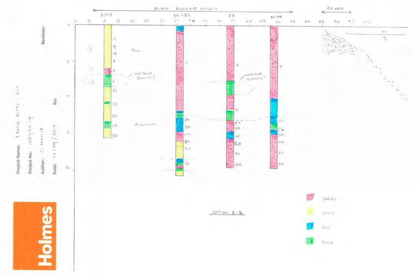
Building Element                                Structural Weakness (SW)                          %NBS(IL3)
                                                   Yielding of the starter bars of the precast
                                                   concrete wall panels for in-plane flexural
                                                   demands.                                                          40%*
 Precast concrete wall panels                      The capacity is limited by the tensile strain
                                                   of the starter bars and the inelastic rotation
                                                   capacity of the precast concrete wall
                                                   panels.
                                                   The double-tee units forming the roof slab
                                                   are web-supported. These, when subjected
                                                   to movement may exceed the capacity of
                                                   the supporting concrete members in
                                                   bearing.

 Double-tee units                                  Note: Visual observations revealed several                        100%
                                                   double-tee units where the seating support
                                                   had already spalled. The remaining seating
                                                   of these units may be insufficient during
                                                   large seismic events and would
                                                   consequently rate lower than 100%NBS
                                                   (IL3).

    •   Shown value corrected in revision 5 to be as per table 3 and as elsewhere in this report.

The Critical Structural Weakness
The Critical Structural Weakness (CSW) is the lowest scoring structural weakness, the failure of which
would result in a significant life safety hazard. The CSW was found to be the roof diaphragm that
distributes the loads between the lateral load resisting systems. The roof diaphragm is reinforced with non-
ductile mesh and consequently does not provide a reliable load path between the lateral load resisting
systems.

Further commentary on the performance of the diaphragm is provided in Sections 5.3 and 10C.4.

Engineering assessment summary report
An Assessment Summary Report has been prepared in accordance with the Engineering Assessment
Guidelines, and to fulfil the requirements of Section 2.5 of the Earthquake-prone Building Methodology. This
can be found in Appendix A.

                                                                                          Frank Kitts Carpark DSA           Revision 5
                                                                                                         105978.19                   2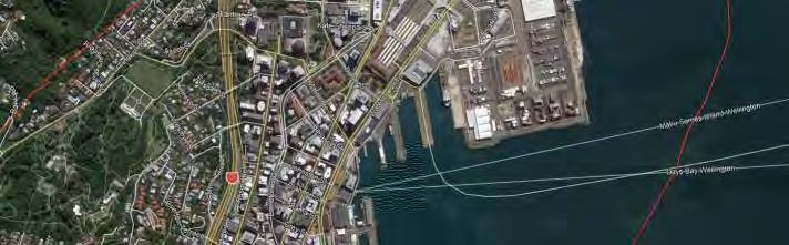
1 INTRODUCTION AND BACKGROUND
Holmes Consulting LP have been engaged by Wellington City Council to complete a Detailed Seismic
Assessment (DSA) of Frank Kitts Carpark, at 15 Jervois Quay, Wellington.
The objective of a Detailed Seismic Assessment (DSA) is to inform users about the risk posed to people by
existing buildings under earthquake actions. A DSA specifically considers life safety, egress and protection
of adjacent property by assessing strength and deformation capacity. A DSA provides a more
comprehensive assessment of the likely seismic performance of an existing building than an Initial Seismic
Assessment (ISA).
A DSA quantifies the seismic behaviour of the building as a seismic rating. This is expressed as a
percentage of the standard achieved from application of the building code requirements, or %NBS
(percent New Building Standard). The rating provides a measure of the expected performance from a life
safety point of view, compared with the minimum required by the Building Code for new buildings.
A DSA is also used to determine whether or not a building is Earthquake-prone in accordance with the
definition for an Earthquake-prone building (EPB) in the New Zealand Building Act.
2 SCOPE
The DSA has been completed in accordance with “The Seismic Assessment of Existing Buildings,
Technical Guidelines for Engineering Assessments, July 2017, Version 1” (NZSEE, 2017), referred to as the
“Engineering Assessment Guidelines” within this report. The Engineering Assessment Guidelines are
referenced in the Earthquake-Prone Building methodology, for the identification of Earthquake-Prone
Buildings, as set by the Chief Executive of the Ministry of Business Innovation and Employment under
section 133AV of the Building Act 2004.
Specific guidance on damage limitation and the ability to occupy after an earthquake is not included in a
DSA conducted to the minimum requirements of the Guidelines, unless specifically appended to the scope
of a normal DSA.
The scope of work for this project included the following:
Undertake inspections of the building where required to visually assess and confirm existing
conditions of structural elements.
Undertake a Detailed Seismic Assessment (DSA) of the building using hand calculation methods
and 2D structural modelling with supporting calculations and evaluation.
Collect and analyse existing geotechnical information to assess the response of the site during
seismic events that induce liquefaction/lateral spreading of the surrounding soils and how these
may affect the structure’s performance.
Identify other geotechnical risks that may affect the structure’s performance.
Prepare a DSA report outlining the assessed seismic rating, summary of likely seismic
performance and risks, and also describing analysis methodology, modelling parameters. Include
commentary on possible strengthening options to improve performance where appropriate.
Consideration of the building’s secondary-structural and non-structural ‘parts’ that are classified
as “parts that pose a significant life safety hazard”.
Frank Kitts Carpark DSA Revision 5
105978.19 3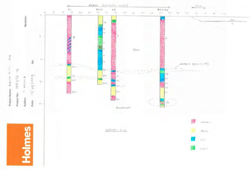
3 TERMINOLOGY AND KEY DEFINITIONS
The communication of seismic risk and assessed seismic behaviour of the building use the terminology
defined in the Engineering Assessment Guidelines. Key terms and acronyms used in this report include:
Earthquake rating – The rating given to a building as a whole to indicate the seismic standard
achieved in regard to human life safety compared with the minimum seismic standard required of
a similar new building on the same site. Expressed in terms of %NBS.
Ultimate Limit State (ULS) shaking demand – the shaking demand (loading or displacement)
defined for the ULS design of a new building and/or its members for the same site.
Percent New Building Standard (%NBS) – The ratio of the ultimate capacity of a building as a
whole or of an individual member/element and the ULS shaking demand for a similar new building
on the same site, expressed as a percentage.
Structural Weakness (SW) – An aspect of the building structure and/or foundation soils that
scores less than 100%NBS.
Severe Structural Weakness (SSW) – A defined SW that is potentially associated with
catastrophic collapse and for which the capacity may not be reliable assessed based on current
knowledge.
Critical Structural Weakness (CSW) – The lowest scoring structural weakness determined from a
DSA.
Frank Kitts Carpark DSA Revision 5
105978.19 44 BUILDING DESCRIPTION
The Frank Kitts Carpark building is a single storey carpark structure located on Jervois Quay, Wellington.
The building was designed and constructed by 1989. Its main purpose is to function as a carpark building
while the roof is used as a public park/open space. The carpark is also used to hold weekend markets and
outdoor festivals in the public space above the carpark.
The plan of the carpark comprises No.9 bays in transverse direction (E-W) and No.10 bays in longitudinal
direction (N-S). The structure is formed by precast concrete wall panels around the perimeter, precast
concrete frames and a flooring system comprising precast concrete double-tee units with a cast in-situ
topping.
The flooring system forms the roof to the structure which supports a layer of soil and pavement. The
concrete walls extend above the roof around the perimeter forming a concrete upstand.
Circular concrete planter boxes are provided to allow for trees and large bushes. Concrete stair elements
are provided at various locations to provide access to the roof structure and in the South-West corner there
is access from a footbridge that goes across Jervois Quay.
The precast wall panels and precast concrete frames are supported by concrete foundation beams and
pads that are founded on a combination of bored concrete piles and driven precast concrete piles. There is
no structural ground floor slab in the building, the bases of the columns are tied together by small concrete
tie beams.
Figure 1 – Extract from Google Maps – Frank Kitts Carpark location
4.1 Gravity load resisting system
The floor system is typically formed by precast concrete double-tee units with insitu topping, forming the
roof to the building. Around the circular planter boxes and at locations around the concrete staircases the
slab is executed as a cast in-situ slab. The double-tee units span between the precast concrete gravity
frames and perimeter walls in the North-South direction.
Frank Kitts Carpark DSA Revision 5
105978.19 5Gravity frame columns are typically sized 300x600, supported by reinforced concrete foundation pads
and driven precast concrete piles. The precast concrete wall panels are supported on reinforced concrete
foundation beams founded either precast concrete driven piles or reinforced concrete bored piles.
4.2 Earthquake (lateral load) resisting system
Lateral loads are distributed by the suspended concrete roof diaphragm to the precast concrete wall
panels at the perimeter of the building then into the wall foundations. There is no structural ground floor
slab provided to the building, the base of the columns being linked together with relatively small tie beam
members.
The precast concrete frames, in the East-West direction, are not considered part of the primary lateral load
system, intended to support gravity loads only.
4.3 Foundations and subsoil
The Geotechnical Assessment is attached in Appendix B. It states that the ground model consists of
approximately 12m of loose gravelly fill overlying dense to very dense alluvium.
Existing borehole investigations were not sufficient to differentiate the site subsoil class between C and D.
Further geotechnical assessments indicated that the site natural period may lie between a C and D site.
Therefore, the recommendation is to adopt a D site, being the more conservative site subsoil for the
assessment of the structural response.
The ground water level was determined to be approximately 1.8m below the ground floor level of the
structure. However, it will obviously be fluctuating with tidal movements in the harbour.
Liquefaction is considered possible within the loose gravelly fill layer. It was also found that the behaviour
of the liquefied soil undergoes a significant step change between 20% and 30% of ULS seismic loading. The
consequence of the step change is connected with the expected cyclic displacements and lateral spread.
Following the step change the lateral spread displacements at the site may be between 1m to 5m.
The step change in the geotechnical behaviour may result directly into a step change in the structural
behaviour, as it does lead to increased demands on the foundation elements of the structure. This is further
described in Sections 5.3 and 10C.8.
Therefore, in accordance with Section C4.5.3.2 of the Engineering Assessment Guidelines, the seismic
response of Frank Kitts Carpark is considered to be structurally and geotechnically interactive in
accordance with the Engineering Assessment Guidelines.
Frank Kitts Carpark DSA Revision 5
105978.19 65 ASSESSED SEISMIC RATING
We have assessed the seismic rating for the Frank Kitts Carpark as 15%NBS(IL3)
The results of the DSA indicate the building’s seismic rating to be 15%NBS (IL3). The performance of the
structure is governed by the roof diaphragm. The diaphragm is reinforced with non-ductile cold drawn
mesh which is not considered to provide a reliable load path between the lateral load resisting systems.
Further commentary on the performance of the diaphragm is provided in Sections 5.3 and 10C.4.
Relative earthquake risk compared with a new building
The building is classified as a Grade E building following the NZSEE grading scheme, as shown in Table 2.
Grade E buildings represent a risk to occupants comparable to greater than 25 times that expected for a
new building, indicating a very-high risk exposure relative to a new building if a large earthquake occurs.
Table 2: Grading system for earthquake risks relative to a new building
Percentage of New Building Approx. risk relative to a new
Grade Life-safety risk description
Standard (%NBS) building
>100 A+ Less than or comparable to Low risk
80-100 A 1-2 times greater Low risk
67-79 B 2-5 times greater Low to Medium risk
35-66 C 5-10 times greater Medium risk
20-34 D 10-25 times greater High risk5.1 Identified Structural Weaknesses
A Structural Weakness (SW) is any aspect of the building structure and/or foundation soils that scores less
than 100%NBS (IL3). Table 3 lists all the Structural Weaknesses (SW) identified in the Frank Kitts Carpark.
Table 3 - Structural Weaknesses identified in the DSA
Building Element Structural Weakness (SW) %NBS(IL3)
The roof diaphragm contains non-ductile mesh
which cannot be relied to provide a load path for
Roof diaphragm the diaphragm forces. 15%
Further commentary on the performance of the
diaphragm is provided in Sections 5.3 and 10C.4.
The precast concrete wall panels are connected
Connection between roof diaphragm and to the diaphragm at the roof level by starter bars.
15%
lateral load resisting system These starter bars are insufficient for the required
shear transfer.
Onset of liquefaction and lateral spread
displacements imposing significant
Reclamation fill seismic performance and
displacements demands on the foundations and 20 – 30%
soil-structure interaction
structure. This may lead to undesirable behaviour
in the superstructure and potential for collapse.
Yielding of the starter bars of the precast
concrete wall panels for in-plane flexural
demands.
Precast concrete wall panels 40%
The capacity is limited by the tensile strain of the
starter bars and the inelastic rotation capacity of
the precast concrete wall panels.
The double-tee units forming the roof slab are
web-supported. These, when subjected to
movement may exceed the capacity of the
supporting concrete members in bearing.
Double-tee units Note: Visual observations revealed several 100%
double-tee units where the seating support had
already spalled. The remaining seating of these
units may be insufficient during large seismic
events and would consequently rate lower than
100%NBS (IL3).
Other elements that could present a significant life safety hazard were assessed as having strength and
deformation capacities above 100% NBS (IL3).
Frank Kitts Carpark DSA Revision 5
105978.19 8The Critical Structural Weakness was found to be the diaphragm
The Critical Structural Weakness (CSW) is the lowest scoring structural weakness, the failure of which
would result in a significant life safety hazard. The CSW was found to be the diaphragm that distributes the
loads between the lateral load resisting systems. The diaphragm is reinforced with non-ductile mesh and
does not provide a reliable load path between the lateral load resisting systems.
Further commentary on the performance of the diaphragm is provided in Sections 5.3 and 10C.4.
5.2 Secondary structural and non-structural elements
The secondary structural and non-structural aspects (SSNS) that were considered in this assessment are
listed in Table 4. Consideration includes a decision to include or exclude these elements from an overall
%NBS Assessed Seismic Rating. The intent of the EPB Methodology is to identify and rate those building
parts which, should they lose support or collapse, would present an unavoidable danger that a number of
people are exposed to.
Section 2.4.1 of the EPB Methodology is applied, using the guidance in Section A4.3.2 of the Engineering
Assessment Guidelines, to determine which parts are included or excluded from the rating. These items are
discussed in more detail in Section 10C.9.
Building contents are not considered in this assessment.
Table 4 - Secondary structural and non-structural elements
Building Part Included in this assessment
Circular planter boxes at several locations in the structure No
Masonry walls in boat sheds on the Southern end of the structure No
Statue/Flag/Pole on roof of structure No
Look-out tower (the Oriel) at the South-West corner of the building Yes
Wall cap on the perimeter wall Yes
5.3 Commentary on structural weaknesses
Comparison between original design requirements (1989) and current requirements
The original design calculations and assumptions from the 1989 building consent documentation were
available for review during the assessment process. This provided valuable insights in the level of seismic
actions that were used for the original design of the structure and to compare these against current design
loading.
Frank Kitts Carpark was designed in accordance with the seismic design actions specified in NZS4203:1984
while current seismic design actions are specified in NZS1170.5:2004.
The difference between the seismic design coefficient from each standard are illustrated in Table 5 and
Figure 2. It can be seen that the building was originally designed for seismic loads which are approximately
19% of the current seismic design loadings.
Frank Kitts Carpark DSA Revision 5
105978.19 9Table 5 - Comparison of parameters used to determine the seismic coefficient between
NZS4203:1984 and NZS1170.5
Parameter NZS 4203:1984 NZS1170.5:2004
Ground conditions Flexible soil Sub-soil class D
Ch(T) 3.0
Structure’s fundamental period C 0.15 T < 0.45s T < 0.4s
Location Zone A Z 0.4 Wellington
Risk factor R 1.0 Category 4 1 Ru 1.3 Importance level 3
Structure type S 2.0 Case 6 2
Reinforced non-
Structure materials M 0.8
prestressed concrete
Near-fault factor N 1.0 T < 1.5s
Structure ductility kµ 1.143 Structural ductility
factor approximated
Structural response factor Sp 0.925 at µ = 1.25
∙ ∙ ∙ ∙
Seismic design coefficient Cd 0.24 C·S·R·M C(T) 1.26
Figure 2 - Seismic spectra comparison between NZS4203:1984 and NZS1170.5:2004
1
In NZS4203:1984, category 4 buildings included ‘buildings with normal occupancy or usage’.
2
In NZS4203:1984, case 6 buildings included ‘single-storey cantilevered buildings supported by face loaded walls constructed of
reinforced masonry or concrete.
Frank Kitts Carpark DSA Revision 5
105978.19 10The capacity of the diaphragm
The roof diaphragm consists of 65mm thick concrete slab that is reinforced with 665 mesh – a cold drawn
wire mesh product. The roof diaphragm is required to distribute seismic inertia load of the structure to the
lateral load resisting systems.
Cold drawn wire mesh has a non-ductile or brittle behaviour, with low elongation capacity, under tension.
Non-ductile mesh has been observed to perform poorly in floor/roof diaphragms in previous New Zealand
earthquakes such as the 2010/2011 Canterbury and 2016 Kaikoura events. Failure and fracture of this mesh
was observed in buildings in Christchurch and Wellington from these earthquake events.
The 2017 Engineering Assessment Guidelines do not directly comment on the appropriate method to assess
diaphragms with this type of non-ductile reinforcing. A crude analysis was undertaken to estimate the
performance of the diaphragm, however this resulted in a very low rating of the diaphragm which may be
not representative of the actual situation. More comprehensive analysis is not discussed in Chapter C5 of
the Engineering Assessment Guidelines, and therefore alternative methods have been considered.
Reference to the latest industry best practice, captured in ASCE 41-17 and the proposed revision of Chapter
C5 of the Engineering Assessment Guidelines (“Yellow C5”) has been made to provide commentary on the
expected seismic performance of this diaphragm. Yellow C5 and ASCE 41-17 state that an elastic analysis
can be performed where the total strain captures the effects from the segmental nature of the individual
components (e.g. the effects from shrinkage and creep are included in the assessment of strains induced in
the mesh reinforcement). Furthermore, Yellow C5 states that ‘non-ductile’ mesh should not be relied on in a
strut-and-tie type of diaphragm analysis.
This provides no solution, since an analysis that includes the effects from shrinkage and creep is deemed
impractical and expected to not result in reliable results. This is mainly due to the large number of side-
effects that could significantly affect the parameters in the analysis. Attempting to identify and evaluate
all these parameters is impractical.
Therefore, the capacity of the diaphragm is considered inconclusive and the Engineering Assessment
Guidelines require this to be rated at 15%NBS (IL3)3.
Performance of foundation system
The lateral load resisting system can be split into bracing lines. A bracing line is a gridline that contains
one or more lateral load resisting systems such as the precast concrete wall panels. The distribution of the
lateral load between the bracing lines at roof level has been assumed to be through a rigid diaphragm. And
has included the effects of accidental eccentricity.
In the assessment of the load paths of the structure it is considered that each bracing line takes a portion
of the seismic loading relative to its stiffness. In the analysis, this is done by determining the eccentricity of
the shear centre relative to the centre of mass. This results in gridlines with a lot of precast concrete wall
panels (such as gridline 8) to take a relatively large portion of the seismic actions, since these are relatively
stiffer. For reference, this also results in the precast concrete frames taking nominal earthquake loads since
they are much more flexible.
Each bracing line then transfers the lateral load to its foundation and ultimately the base shear is taken out
by the piles. On the ground floor level however, there is no positive diaphragm to redistribute the forces to
3
The Engineering Assessment Guidelines recommend in Section A8.2 that scoring elements below 15%NBS has no practical meaning
and may provide an erroneous indication of expected performance. Therefore, it is recommended that a scoring or rating is not
quoted as less than 15%NBS.
Frank Kitts Carpark DSA Revision 5
105978.19 11other gridlines. Therefore, the relative stiffness of the bracing lines above the foundation system determines
the load transfer to each individual pile.
This assessment accounts for the participation of both the bored concrete piles and the precast concrete
driven piles in the lateral load resisting system. And the assessment process further accounts for inelastic
displacement capacity of the foundation system, since connections to the foundation beams allow for a
ductile response. Other effects, such as friction between the foundation beams and the ground or passive
soil pressures were found to contribute minimally in the assessment.
The assessment methodology is contrary to the assumptions made in the original 1989 design. From the
calculations of the consent documentation it is found that the total base shear of the entire structure is
assumed to be divided equally over all bored concrete piles, irrespective of their position in the structure.
The precast concrete driven piles were not considered in the lateral load resisting system. Inelastic
behaviour of the members was also not considered.
From the site reports and the as-built drawings it is found that the location of the bored concrete piles is
generally in the Western side of the building. In the Eastern side of the building some bracing lines (such as
gridline H) are equipped with precast concrete driven piles only. This represents a significant deviation of
lateral load distribution philosophy between the original design and the assessment methodology used
here.
The assessment process incorporated in this DSA is considered to be much more comprehensive but results
in yielding of the piles at lower levels of seismic shaking then what was assumed in design. Ultimately
though, the performance of the foundation system is limited by the geotechnical behaviour as outlined
below.
Performance of structure during liquefaction of the ground profile
The geotechnical assessment concluded that during a seismic event, liquefaction can occur up to a depth
of approximately 11m below the foundation pads and beams. Since the piles have a length of
approximately 12m, this essentially means that during a seismic event the piles will only have an
embedment in non-liquefied ground of 1m.
The geotechnical assessment further states that liquefaction occurs even at very low levels of seismic
shaking and that a significant geotechnical behaviour step-change may be expected at seismic shaking of
20-25% of ULS accelerations. This step-change may induce significantly larger cyclic displacements and
lateral spread.
To assess the foundations of the structure during a seismic event that triggers liquefaction, 4 scenarios are
considered. The geotechnical investigations show that once the seismic shaking reaches the level of
shaking that triggers the step-change, then the liquefied scenarios 2, 3 and 4 are expected to significantly
impact the structure. The scenarios that are considered are:
1. 100% of inertia combined with non-liquefied soils
2. 100% of inertia combined with liquefied soils
3. 80% of inertia combined with liquefied soils and cyclic displacements
4. Liquefied soils combined with lateral spread
These scenarios are selected based on the guidance by design manuals such as NZGS/MBIE: Module 4:
2016 and the NZTA Bridge Manual version 3.3: 2018. These indicate that it is unlikely that the full dynamic
response of the building would be superimposed simultaneously with the full kinematic loading on the pile.
Frank Kitts Carpark DSA Revision 5
105978.19 12The first scenario is unlikely to occur due to the high proneness of the ground to liquefy. However, the soil
may respond initially without liquefaction and the 4 scenarios could occur in sequence. If this is the case,
then the assessment shows that the piles would hinge at approximately 10% of ULS seismic loading. The pile
has the ability to deform inelastically however and can perform at a higher level of loading, if the ground
doesn’t liquefy.
When the ground does liquefy (scenario 2, 3 and 4), then the pile is essentially only supported in its
embedment 11m below the foundation pads and beams. This results in period elongation and may reduce
the seismic inertia from the structure. The embedment length of the pile in approximately 1m of soil is
however not enough to generate fixity. And this means that when the piles hinge at the top, there is no
reliable load path that provides lateral restraint to the structure.
Furthermore, the embedment length of approximately 1m does not provide a large restraint. It may
therefore equally happen that the capacity of this pocket is exceeded and that the pile may ‘pop’ out of
the shallow embedment. Even if the pile has not hinged at the top yet, the consequence of this is similar, as
the pile has no reliable load path anymore that provides lateral restraint to the structure. Both resulting
scenarios are illustrated in Figure 3.
Figure 3 - Illustration of pile behaviour under liquefaction scenarios
where: V*b describes the inertia of the structure itself
Ground displacements are caused by cyclic displacements or lateral spread
PPHZ refers to the location of a potential plastic hinge zone in the pile
The assessment has found that there are a lot of uncertainties that come with both the capacity of the
structure, particularly the piles, and the demand under liquefied ground conditions. One of the critical
parameters that is possible to be determined with more certainty, however, is the step-change in
geotechnical parameter that occurs at 20-30% of ULS seismic demands. Exceeding this level of shaking
may trigger large cyclic displacements and lateral spread of up to 5m. For this reason, the assessment
concludes that the capacity of the piles is 20-30%NBS (IL3) which is limited by the structural
performance/capacity of the piles following the onset of liquefaction and lateral spread.
Frank Kitts Carpark DSA Revision 5
105978.19 13It is noted that a step change in the geotechnical that leads to a step change in the structural behaviour
that may lead to a collapse event is required to lower the performance of the structure by a factor of 0.5.
However, as described in the Geotechnical Assessment in Appendix B, there is sufficient certainty from the
geotechnical assessment to not use this factor in the performance assessment of the foundation elements
based on the performance of the structure and the ground during the 2016 Kaikoura Earthquake event.
6 BASIS OF THIS REPORT
The Detailed Seismic Assessment (DSA) has been completed in accordance with “The Seismic Assessment of
Existing Buildings, Technical Guidelines for Engineering Assessments, July 2017, Version 1” (NZSEE, 2017).
This document is referred to in this report as the Engineering Assessment Guidelines.
6.1 Information available for the assessment
The assessment has been based on the following information:
1989 complete set of architectural and structural drawings of Frank Kitts Carpark from original
designers at BECA
Construction specifications from 1989 prepared by original designer BECA
Calculations package from 1989 prepared by original designer BECA
Incomplete set of shop drawings of precast elements from 1989
Load assessment report from 2018
Geotechnical report by Holmes Consulting LP dated 8/11/2019 – Appendix B
The construction drawings appeared to be repeatedly updated during the design process and are
considered to be close to the as-built status. However, minor conflicts were found between the consent
package, the construction drawings and the shop drawings. Where these conflicts were observed the
following order of priority was given to the available information:
1. Site observations
2. Shop drawings
3. Construction drawings
4. Consent documentation
The following information was not available for the assessment:
Shop drawings of the precast concrete wall panels
Shop drawings of the double-tee units
6.2 Site observations and investigations
A visit to the Frank Kitts carpark was carried out in September 2019. The purpose of the visit was to visually
observe important structural and seismic characteristics, assess their condition and note obvious
deficiencies or differences from the documentation. Particular locations that were investigated in more
detail were:
General walkovers were undertaken to confirm the global geometry of the Frank Kitts carpark
and to identify secondary and non-structural elements that would influence the assessment of the
carpark.
The connection between precast shear wall panels.
The as-constructed structure appears to be generally consistent with the available drawings. No significant
modifications appear to have been made to the primary lateral or gravity systems.
Frank Kitts Carpark DSA Revision 5
105978.19 14Material testing has not been completed. Material properties based on values in the original documentation
are considered sufficient for this assessment. Our observations have been visual only.
6.3 Earthquake demand used in the assessment
The Ultimate Limit State (ULS) seismic demand is derived from the New Zealand Structural Design Actions
Standard, NZS1170.5:2004 Incorporating Amd. 1 (Standards New Zealand, 2016). Factors that affect the
earthquake demand are described below.
Building importance level
We have assumed Importance Level 3 a major structure affecting crowds with a 50 year design life, in
accordance with the New Zealand Structural Design Actions Standard NZS1170.0:2002 (Standards New
Zealand, 2011), for the analysis of the Frank Kitts Carpark.
The New Zealand Structural Design Actions Standard NZS1170.5:2004, requires the use of a higher level of
load for Importance Level 3 buildings for the design of new structures. Normal buildings are regarded as
Importance Level 2 and are designed for an earthquake with and annual probability of exceedance of
1/500. An Importance Level 3 building is designed for a load level approximately 30% greater (a ‘risk factor’
of R=1.3). This equates to an earthquake with and annual probability of exceedance of 1/1000.
Seismic hazard zone
Wellington CBD is located in a zone of relatively high seismicity. The Wellington Fault passes within 400 m
of the site. We have used a hazard factor of Z=0.40 and near fault factors in accordance with
NZS1170.5:2004.
Site and subsoil class
Seismic loads are also dependent on the soil type a structure sits on. In accordance with the
recommendations from the geotechnical assessment, a Site Soil Class of D has been used.
7 METHOD OF ASSESSMENT
The method of assessment is selected in accordance with the recommendations of Section C2 of the
Engineering Assessment Guidelines, as summarised in Table C2.1 of those Guidelines.
Equivalent Linear Static analysis
The equivalent static lateral force method is a simplified technique to substitute the effect of dynamic
loading of an expected earthquake by a static force distributed laterally on a structure for design
purposes. The total base shear is evaluated in the two horizontal directions parallel to the main axes of the
building. It assumes that the building responds in its fundamental lateral mode. The building is low-rise and
is fairly symmetric. Therefore, torsional movement due to ground motions can be captured with reasonable
confidence. The use of equivalent static method is used for the primary and secondary and non-structural
elements in the assessment.
The analysis has assumed a structural displacement ductility of µ = 1.25. This simulates a nominal ductile
structure and allows for minimal inelastic behaviour in the structure. The analysis has shown that there is a
number of elements that respond with minimal inelastic deformations which coincides with this assumption.
Further information/technical details on seismic loads, analysis procedures and evaluation can be found in
10Appendix C.
Frank Kitts Carpark DSA Revision 5
105978.19 158 STATUTORY REQUIREMENTS FOR EXISTING BUILDINGS
When working with existing buildings, there are statutory requirements that must be considered, these vary
depending on whether the building is considered to be potentially Earthquake-prone.
Frank Kitts Carpark is considered potentially Earthquake-prone, and therefore, the relevant sections of the
New Zealand Building Act 2004 and the Building (Earthquake-prone Buildings) Amendment Act 2016 that
need to be considered in relation to the building’s structure and strength are set out as follows.
8.1 Requirements under the Building Act 2004 (as amended by the Earthquake-prone
Buildings Amendment Act 2016)
The Building (Earthquake-prone Buildings) Amendment Act 2016 took effect on the 1 July 2017. This Act
provides a national policy framework for managing Earthquake-prone buildings. The three main steps of
the framework are:
Territorial Authorities (TAs) must identify potentially Earthquake-prone buildings
Building owners of potentially Earthquake-prone buildings must commission an engineering
assessment
TAs must use this information to determine whether or not a building or part is Earthquake-prone.
Key features of the act are described below:
Earthquake-prone buildings
An Earthquake-prone building is a building (or part of a building) that will have its ultimate capacity
exceeded in a moderate earthquake (have an earthquake rating less than 34%NBS) and if the building (or
part) were to collapse, the collapse would likely cause injury or death to persons, or cause damage to any
other property.
The Territorial Authority (TA) in whose district the building is situated, determine if a building is
Earthquake-prone. The earthquake rating (%NBS), mode of failure and physical consequence
identified by an accepted engineering assessment informs this decision. However, the TA’s
decision will also depend on occupancy, accessibility, neighbouring buildings and their proximity.
A moderate earthquake is an earthquake at the site that is the same durations, but one-third as
strong and the earthquake shaking that would be used to design a new building at that site
(33%ULS loading).
An Earthquake-prone building can be one that poses a risk to people on adjoining properties and
not just those within the building itself.
Excluded from the definition of ‘Earthquake-prone building’ are certain residential housing, farm
buildings, retaining walls, wharves, bridges, tunnels and monuments.
Included in the definition of ‘Earthquake-prone building’ are hostels, boarding houses and
residential housing that is more than two storeys and contains three or more household units.
Seismic risk locations
Different locations are assigned different ‘seismic risk’. There are three different categories defined by the
seismic hazard factor (Z) in the New Zealand Loadings Code (NZS 1170)
• High seismic risk – Z factor greater than or equal to 0.3
• Medium seismic risk – Z factor between 0.15 and 0.3
• Low seismic risk – Z factor less than 0.15
The seismic risk relates to timeframes for strengthening and identification of potentially Earthquake-prone
buildings. Wellington is considered a High Seismic Risk region.
Frank Kitts Carpark DSA Revision 5
105978.19 16Priority buildings
Priority buildings are defined as buildings in areas of high or medium seismic risk that:
Are generally used for health or emergency services or as educational facilities.
Contain unreinforced masonry (such as parapets) that could fall onto busy thoroughfares in an
earthquake –
The territorial Authority has identified as having the potential to impede strategic transport routes
after an earthquake.
Priority buildings have shorter timeframes for identification and strengthening of Earthquake-prone
buildings.
Frank Kitts Carpark is not classed as a High Priority Building.
Timeframes for identifying potentially Earthquake-prone buildings
TAs need to assess and identify potentially Earthquake-prone buildings as outlined below.
High seismic risk areas:
High Priority buildings January 2020
All other buildings July 2022
Medium seismic risk areas:
High Priority buildings July 2022
All other buildings July 2027
Low seismic risk areas:
All buildings July 2032
Frank Kitts Carpark is considered to be in a high seismic risk area and is a low priority building. Therefore, it
needs to be assessed as a potential Earthquake-Prone Building prior to July 2022.
Earthquake-prone building (EPB) notice
Following identification as a potentially Earthquake-prone building, building owners are required to provide
the TA with an engineering assessment of the building within twelve months (unless an extension is
granted). When the TA receives the engineering assessment they determine if a building is Earthquake-
prone. If the TA determine a building is Earthquake-prone, an EPB notice is issued which must be displayed
in a prominent place on or adjacent to the building. The TA may also restrict access to the building.
Engineering assessments can be sent to the TA at any time to determine the EPB status of a building.
Timeframes for strengthening Earthquake-prone buildings
Seismic work must be completed within the following periods, measured from the date the EPB notice was
issued.
High seismic risk areas:
High Priority buildings 7.5 years
All other buildings 15 years
Medium seismic risk areas:
High Priority buildings 12.5 years
All other buildings 25 years
Low seismic risk areas:
All buildings 35 years
Frank Kitts Carpark DSA Revision 5
105978.19 17If an Earthquake-Prone Building notice is issued for Frank Kitts Carpark than strengthening will need to be
completed within 15 years of notice issue.
Alterations and change of use
In addition to legislation covering consideration of Earthquake-prone buildings, other relevant sections of
the Building Act are:
Section 112: Alterations to existing buildings. Section 112 of the Building Act requires that a
building subject to an alteration continue to comply with the relevant provisions of the Building
Code to at least the same extent as before the alteration. Essentially this section means that the
building may not be made any weaker than it was as a result of any alteration.
Section 115: Change of Use. Section 115 of the Building Act requires that the territorial authority
(Wellington City Council) be satisfied that the building in its new use will comply with the relevant
sections of the Building Code “as nearly as is reasonably practicable”. In relation to building
earthquake strength, this does not necessarily require the building to comply in full with the
current Building Code, provided that it can be shown that full compliance is impractical, or that
the cost (by any relevant measure of value) is unreasonable under the circumstances.
Interpretations would relate to the specific circumstance and would need to be agreed in
dialogue with the territorial authority on a case by case basis.
Section 133AT: Alterations to buildings subject to EPB notice. Specifically, with respect to seismic
work, if any alteration to a building subject to an EPB notice is “substantial”, then the alteration
must include the necessary seismic work which results in the building no longer being classified as
Earthquake-prone. There are also other requirements for alterations specific to earthquake prone
buildings (substantial or not), relating to means of escape from fire, and access/facilities for
those with disabilities. The Building Act and regulations should be referred to for the specific
requirements, including the definition of what constitutes a substantial alteration (NZ Govt, 2016)
(NZ Govt., 2017).
9 LIMITATIONS
Findings presented as a part of this project are issued pursuant to our contract with Wellington City
Council dated 27 June 2019 and for the sole use of Wellington City Council in its evaluation of the subject
property. The findings are not intended for use by other parties and Holmes Consulting assumes no
liability to any party other than Wellington City Council.
Our observations have been visual only and are limited to representative samples. Our observations have
been restricted to structural aspects only. Waterproofing elements, electrical and mechanical equipment,
fire protection and safety systems, service connections, water supplies and sanitary fittings have not been
inspected or reviewed, and secondary elements such as windows and fittings have not generally been
reviewed.
Our findings relate to the structural performance of the building under earthquake actions. We have not
reviewed other loading conditions such as the live load capacity of the floors or wind loading.
Our professional services are performed using a degree of care and skill normally exercised, under similar
circumstances, by reputable consultants practicing in this field at this time. No other warranty, expressed
or implied, is made as to the professional advice presented in this report.
Frank Kitts Carpark DSA Revision 5
105978.19 1810 REFERENCES
ASCE/SEI, 2014. ASCE/SEI 41-13 Seismic Evaluation and Retrofit of Existing Buildings. s.l.:American Society
of Civil Engineers.
ASCE/SEI, 2017. ASCE/SEI 41-17 *Draft for Public Comment* Comment Seismic Evaluation and Retrofit of
Existing Buildings. s.l.:ASCE.
ASCE/SEI, 2017. ASCE/SEI 7-16 Minimum Design Loads and Associated Criteria for Buildings and Other
Structures. s.l.:American Society of Civil Engineers.
Bradley, B. A. & Tarbali, K., 2017. Default ground motion ensembles for response history analysis of
structures in Christchurch, Wellington and Auckland - Revised Draft 22 June 2017, s.l.: Bradley Seismic
Limited.
Fenwick, R., Bull, D. & Gardiner, D., 2010. 2010-02 Assessment of hollow-core floors for seismic performance,
Christchurch: University of Canterbury.
Mondkar, D. P. & Powell, G. H., 1979. ANSR II Analysis of Non-linear Structural Response User's Manual, EERC
79/17. Berkeley: University of California.
NEHRP, 2010. NIST GCR 10-917-5 Nonlinear Structural Analysis for Seismic Design, s.l.: National Institute of
Standards and Technology.
NZ Govt., 2017. Building Regulations 2005 (SR 2005/32) - as amended by Amendment Regulations 2017 (LI
2017/136)). Wellington: MBIE.
NZ Govt, 2016. Building (Earthquake Prone Buildings) Amendment Act 2016. Wellington: MBIE.
NZSEE, 2017. The Seismic Assessment of Existing Buildings, Technical Guidelines for Engineering
Assessments, Initial Release July 2017. Wellington: MBIE.
Preistley, M. J. N., Calvi, G. & Kowalsky, M., 2007. Direct Displacement Based Design of Structures. Pavia:
IUSS Press.
Standards New Zealand, 2007. NZS 3404:1997 Steel Structures Standard, Incorp. Amd. 1 & 2. Wellington:
Standards New Zealand.
Standards New Zealand, 2008. NZS 3101:2006 Concrete Structures Standard, Incorp. Amd. 1 & 2.
Wellington: Standards New Zealand.
Standards New Zealand, 2011. AS/NZS 1170.0:2002 Structural Design Actions Part 0: General principles,
Incorp. Amd. 1 to 5. Wellington: Standards New Zealand.
Standards New Zealand, 2016. NZS 1170.5:2004 Incorporating Amendment 1 - New Zealand Structural
Design Actions Part 5: Earthquake Actions. Wellington: Standards New Zealand.
Frank Kitts Carpark DSA Revision 5
105978.19 19You can also read