Geochemical characterization and assessment of fluoride sources in groundwater of Siloam area, Limpopo Province, South Africa
←
→
Page content transcription
If your browser does not render page correctly, please read the page content below
www.nature.com/scientificreports
OPEN Geochemical characterization
and assessment of fluoride sources
in groundwater of Siloam area,
Limpopo Province, South Africa
Tobiloba Onipe1, Joshua N. Edokpayi1* & John O. Odiyo1,2
Siloam’s groundwater is reportedly characterized by high fluoride. In response to the reported
high incidence of dental fluorosis in the area, sources of elevated fluoride in the groundwater were
investigated. Total fluoride (TF) was determined using Ion Chromatograph and Fluoride Ion Selective
Electrode. The mineral composition of rocks and soils were determined using X-ray Fluorescence and
X-ray diffraction, respectively. Results revealed that groundwater fluoride concentration ranged from
3.92 to 4.95 mg/L. Na-Cl water type was found to be dominant in the water samples. TF content of
the rocks and soils ranged from 10 to 2000 mg/L. Leachates were obtained by making a slurry from
the samples at a predetermined temperature and time. TF in leachates ranged between 0.27 and
14.88 mg/L and 0.05 to 10.40 mg/L at induced, and non-induced temperatures, respectively. The
possible source of fluoride has been previously inferred to be caused by fluorite minerals occurring at
greater depth. However, this study proves that fluoride decreases with depth and the elevated fluoride
in the groundwater is caused by smectite-kaolinite clay, muscovite and chlorite minerals abundant
in the area. Geothermal temperature exhibited by the groundwater in the area is a major factor
enhancing the release of fluoride from the clay materials.
Water is an important basic resource necessary for human development and economic growth. The supply of
clean and safe water over the last decade has improved progressively globally1. Despite this recorded success,
millions of people are not connected to water supply infrastructure and often resort to several alternative sources
for their domestic water n eeds2,3. One of such sources include the exploitation of groundwater4.
Groundwater is the largest deposit of freshwater on earth and is a dependable alternative source of water with
more than 75% of African population depending on it for s urvival5. However, there are various misconceptions
about groundwater that it is free from chemical contamination and pathogens owing to its aesthetic property.
Over the years, studies have shown that groundwater is exposed to various chemical contaminants from natural
geological processes and anthropogenic a ctivities6–8. Groundwater are often exploited in the form of natural
springs, wells and drilling of boreholes.
Several contaminants have been reported in the groundwater which are of potential risk to public health.
Amongst which are the presence of elevated levels of arsenic, lead, cadmium, mercury, fluoride, nutrients and
microorganisms9–11. Some of these contaminants are more linked to geogenic sources than others. Fluoride is
believed to be caused majorly by fluoride bearing minerals with little or no contribution from human activities.
However, groundwater contamination from lead, nutrients and microorganisms are more linked to anthropo-
genic activities such as mining and a griculture10,11.
Fluoride is very important in the healthy development of the skeletal and dental framework of the body, if
present in levels < 0.5 mg/L, can lead to dental caries while concentration exceeding 1.5 mg/L can lead to fluorosis
and no fluorosis diseases. The levels of fluoride vary globally and various climatic, hydrological and geochemical
properties often determine and influence its levels in groundwater. The consumption of fluoride rich water has
been linked to various public health burden notable among which are dental and skeletal fluorosis12–14. Cases of
several non-fluorosis diseases such as Alzheimer’s disease, loss of mobility, infertility, hearing difficulty, retarded
growth, low intelligence quotient and cancer have also been linked to the consumption of fluoride rich w ater9,15–20.
1
Department of Hydrology and Water Resources, University of Venda, Private bag X5050, Thohoyandou 0950,
South Africa. 2DVC: RICl, Vaal University of Technology, Vanderbiljpark, South Africa. *email: Joshua.Edokpayi@
univen.ac.za
Scientific Reports | (2021) 11:14000 | https://doi.org/10.1038/s41598-021-93385-4 1
Vol.:(0123456789)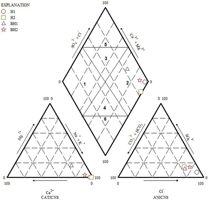
www.nature.com/scientificreports/
Figure 1. Map of the study area (Figure drawn using ArcGIS version 10.4, licensed to the University of Venda,
South Africa).
Occurrence of elevated fluoride in groundwater is an emerging world-wide threat that affects over 200 million
people worldwide and over 80 million people in East A frica21.
The occurrence of high levels of fluoride exceeding the permissible level of 1.5 mg/L by the World Health
Organization has been recorded in many regions of the world. The East Africa rift valley system have been
renowned for high levels of fluoride in groundwater22–24. In most parts of South Africa, elevated levels of fluoride
have been reported in groundwater. The Northern region of the Limpopo Province which is semi-arid consist of
numerous springs which are also known to contain high fluoride concentration9,25,26.
Globally, several efforts have been channeled towards the monitoring of groundwater quality for compliance
to regulatory standard due to the number of people that depends on it for survival27–29. Fluoride compliance study
have been greatly reported in literature7,8,26. However, very few studies have reported the source of fluoride in
groundwater9,18,25. The most important factor controlling the occurrence of fluoride naturally in groundwater is
the rock types (geology) of the area. Fluorine has been reported in all the major rock types (igneous, sedimen-
tary and metamorphic)9,18. Notable geogenic sources that have been reported include fluoride bearing minerals
uorspar9,18,25,30,31.
such as fluorite, villiaumite, apatite, biotite, amphibole, micas, topaz, cryolite, muscovite and fl
In Siloam and the Northern part of South Africa, studies from our research group and other researchers have
shown the occurrence of elevated fluoride concentrations in wells, boreholes (cold and hot) and geothermal
springs25,26,31–34. Siloam area is known for a large-scale occurrence of dental fluorosis amongst children and
adults and according to Odiyo and Makungo35, over 85% of the population in the study area could be affected
by dental fluorosis. The groundwater chemistry of this region has not been fully explored or reported. Therefore,
in this study, we report mainly on the occurrence of fluoride bearing minerals in the region and some factors
that could favor its dissolution.
Description of the study area
Location. The study area (Fig. 1) is located within Makhado Municipality, Vhembe District in Limpopo
Province of South Africa. This includes the northern flank of Tswime Mountain where Mphephu thermal spring
is located. It is 60 km northeast of Makhado and is approximately 45 km west of Thohoyandou. Siloam falls
under surface water and groundwater quaternary catchment A80A of the Nzhelele River catchment, which is in
the northern region of Limpopo Province, South A frica36. The Nzhelele River flows in the northwest direction,
26
towards Nzhelele D am . The prevailing seasons are winter and summer, with average winter temperatures rang-
ing between 16 and 22 °C and average summer temperatures varies between 22 to 40 °C37. Siloam experiences
seasonal rainfall, ranging from 350 – 400 mm per annum in the summer months of September to March36,38.
Rainfall in Siloam is largely influenced by its position on the leeward side of Soutpansberg mountain which plays
an important role in the groundwater recharge of the area35. Evaporation rate is higher than the precipitation
rate at 1300–1400 mm/annum. Siloam is dominated by two major geothermal springs and other hot private and
Scientific Reports | (2021) 11:14000 | https://doi.org/10.1038/s41598-021-93385-4 2
Vol:.(1234567890)
www.nature.com/scientificreports/
Figure 2. Geological map of the study area32, permission granted by Dr. Durowoju).
community borehole. Boreholes in the study area varies in depth and are usually within the range of 65–85 m
and the mean depth to groundwater is about 15–25 m33.
Geology. Siloam lies within the Soutpansberg group (Fig. 2). Soutpansberg group is a Mokolian age exten-
sively faulted succession that provides a link between the pre-and post-Bushveld age (younger than 1800 mya)
rocks39. The Soutpansberg succession is an east to west trending asymmetrical rift overlying the Palala shear
belt39. Soutpansberg group is subdivided into six formations namely: Tshifhefhe formation, Sibasa formation,
Fundudzi formation, Wyllie’s formation, Musekwa formation and Nzhelele f ormation40,41. The Palala shear belt
separates the Kaapval craton in the South and the Limpopo belt in the North39. The area has been through differ-
ent post-deposition tectonic and erosional activities. The evolution of Soutpansberg started with the deposition
of basaltic lava as a result of volcanic activities, followed by the deposition of syn-rift sequence of sedimentary
rock. The area was subjected to an extensive erosional period of non-deposition after which resistant sandstone-
quartzite was deposited42. Unconformable deposition of Karoo supergroup sediments occurred and altogether,
went through the process of block-faulting43. The sequence is best developed from north of Siloam fault to
Musekwa mountains44.
Materials and methods
Sampling of soil, water and rock. One soil and rock samples were collected from the surface in the study
area while twelve borehole cuttings from the subsurface were sampled for analysis. Four water samples were col-
lected across the area. The samples were collected using plastic cups as recommended by Harvey45. For each loca-
tion, the samples were collected three times in a 1 L sampling bottle and were transported to the laboratory for
analysis. As suggested by Weaver et al.46, the bottles were pre-rinsed with the water to be sampled, to avoid cross
contamination. The groundwater samples for anion analysis were preserved in a refrigerator at a temperature of
4 °C and analyzed within seven days of collection. However, the samples for cation and trace metals analysis were
preserved with concentrated nitric acid. Table 1 below summarizes the sample types and number.
Measurement of basic water quality parameters. The pH, electrical conductivity (EC) and tempera-
ture were measured insitu using a multimeter (Multi 340i/SET). The instrument was calibrated prior to measure-
ment in adherence to the manufacturer’s guideline.
Scientific Reports | (2021) 11:14000 | https://doi.org/10.1038/s41598-021-93385-4 3
Vol.:(0123456789)www.nature.com/scientificreports/
Sample type Sample ID Depth (m) Location No of samples
Water samples
22° 53′ 34.008″ S
Monitoring borehole 1 BH1 > 60 1
30° 11′ 47.22″ E
22° 53′ 38.148″ S
Monitoring borehole 2 BH2 > 60 1
30° 11′ 18.52″ E
22° 53′ 39.43" S
Private Borehole 1 H1 > 60 1
30° 11′ 43.94" E
22°53′43.39"S
Private Borehole 2 H2 > 60 1
30°11′32.98"E
Rocks and soil samples
22° 53′ 34.83″ S
Surface Soil Sample S1 N/A 1
30° 11′ 45.56″ E
22° 54′ 22.8″ S
Surface Rock Sample 1 SR2 N/A 1
30° 10′ 44.0″ E
22° 52′ 02.5″ S
Surface Rock Sample 2 SR3 N/A 1
30° 12′ 09.7″ E
22° 53′ 34.008″ S
Borehole 1 Cuttings X 1–65 6
30° 11′ 47.22″ E
22° 53′ 38.148″ S
Borehole 2 Cuttings Y 1–40 6
30° 11′ 18.528″ E
Table 1. Description of Sample types. N/A not available.
Major anions analysis. Groundwater samples were analyzed for major anions content (fluoride, nitrate,
phosphate, bicarbonate) using an Ion Chromatograph (Dionex Model DX 500). Prior to analysis, the samples
were filtered using 0.45 μm syringe filter. The samples were placed in vails associated with an auto sampler1. The
EC of the samples were below 500 µs/cm hence dilution was not done.
Trace elements analysis for groundwater and rock samples. Major cations in the acidified ground-
water water samples were analyzed using Inductively coupled plasma optical emission spectrophotometer (ICP-
OES) while Inductively coupled plasma mass spectrophotometer (ICP-MS) were used for the analysis of trace
metals. Similarly, Trace and major metals in the soil and rock samples were analyzed using the same analytical
instruments outlined above after microwave digestion. The procedure reported by Pais and Jones47 for soil and
rock sample digestion were adhered to. Briefly: The soil/rock samples were digested using a microwave digestion
system (SR ISO 11,466: 1999). Approximately 1.0 g of pre-treated samples were digested with 9 mL HNO3 and
1 mL H2O2. The solutions were allowed to stay overnight at room temperature and then, placed in the microwave
for 30 min, followed by cooling. The solutions were diluted to 50 mL with distilled water.
Preparation of soil and rock samples. The rocks and soil samples for X-ray diffractometer (XRD) analy-
ses were prepared according to the standardized PANalytical backloading system, which provides nearly random
distribution of the particles, while the samples for X-ray fluorescence (XRF) were prepared as pressed powders48.
The rock samples were split, washed, dried, crushed and pulverized. Splitting into chips was done by a hydraulic
splitter after which the split chip was washed and treated with ultrasound wave to remove any loose impure
particles. After washing, the samples were dried overnight in an oven to remove excess water introduced dur-
ing washing of the samples. A jaw crusher was used to crush the samples which were further reduced to finer
grain (< 40 μm in diameter) by pulverizing them for about five (5) min using a Retsch RS 200 miller. The milled
samples were transferred to a paper bag and oven dried at 110 °C for 6 h. After oven drying, the samples were
further milled to less than 20 µm48.
Samples for total fluoride in soil and rocks were prepared by weighing 0.2 g of the samples in a nickel cru-
cible, 2 g of C
aCO3 and N a2O2 was added, respectively. The mixture was fused manually to aid leaching, using
a low flame bunsen burner in a fume box. Auto fusion was avoided to prevent burning of the nickel crucibles
and ensure that N a2O2 does not get moist. 250 mL plastic beakers were pre-washed in a heated Eco bath using
concentrated HCl. The heated crucibles were transferred into 250 mL plastic beakers where 50 mL of de-ionized
water and 8 mL of HCl were a dded49. The mixtures were covered with a plastic lid and placed on warm bath until
the samples were leached out of the crucibles. The crucibles were washed with de-ionized water to make sure that
all the leachate was removed from the crucibles. The solutions were transferred into 100 mL volumetric flask and
diluted to mark. Blank was prepared by fusing 2 g of CaCO3 and Na2O2. The fused mixture was transferred into a
250 mL beaker and 100 mL of de-ionized water and 16 mL of concentrated HCl were a dded48. The mixture was
allowed to leach out and the crucible was rinsed with distilled water. The leachate was transferred into a 200 mL
volumetric flask and filled to mark with de-ionized water. Calibration was carried out using 0.1 ppm, 1 ppm,
10 ppm, 100 ppm and 1000 ppm fluoride standards. The standards, samples and blanks were all mixed in equal
proportion with TISAB II in a 1:1 ratio.
Calibration of pH meter was done using buffers 6.00 and 4.00. The Slope was 97.9% which fell within the
recommended slope limit of 95 to 105%. The pH of the samples and blanks were adjusted to 6.00 using 50%
NaOH and HCl. The pH was adjusted because at pH below 5, hydrogen ions complex a portion of the fluoride
Scientific Reports | (2021) 11:14000 | https://doi.org/10.1038/s41598-021-93385-4 4
Vol:.(1234567890)www.nature.com/scientificreports/
ions, forming HF or H F2, which cannot be detected by the fluoride e lectrode49. Likewise, in a solution with pH
above 9, the electrode responds to hydroxide ion as well as to fluoride ion giving an exaggerated reading. Sam-
ples for leachable fluoride in soil and rocks were prepared by mixing 10 g of the sample with 100 mL of distilled
water at a ratio of 1:10. The samples were prepared in duplicate to ensure that each sample is represented under
induced temperature and room temperature. The first set of samples were shaken in a warm bath at normal
room temperature for 6 h48. The second set of samples were shaken in a warm bath at a temperature of 42 °C.
Because of the clay contents of the sample the mixture was centrifuged for 10 min at a speed of 3000 rpm. The
centrifuged samples were decanted and filtered using a 9 cm filter paper. The resultant mixture was then further
filtered using a 40 µm syringe filter to ensure that all impurities that could block the IC column were removed.
The EC of the samples were below 500 µs/cm hence dilution was not required.
Lithology and mineral phase identification. The minerals in the rocks and soil samples from Siloam
were identified and quantified using X-ray diffraction method of analysis. The samples were analyzed using a
PANalytical X’Pert Pro powder diffractometer in θ–θ configuration with an X’Celerator detector and variable
divergence and fixed receiving slits with Fe filtered Co-Kα radiation (λ = 1.789 Å). The phases were identified
using X’Pert Highscore plus software. The relative phase amounts (weight%) were estimated using the Rietveld
method (Autoquan Program). The angles of the peaks were used to identify the mineral phase while the intensi-
ties of the peaks indicated the abundance of each mineral50.
Total oxide analysis. The total rock and soil oxides were measured using X-ray Fluorescence analytical
method. The ARL Perform’X Sequential XRF instrument with Uniquant software was used for the analyses51.
The software analysed for all elements in the periodic Table between Na and U, but only elements found above
the detection limits were reported51. The intensities for all elements were corrected automatically for line inter-
ference and absorption effects due to all the other elements using the fundamental parameter m ethod49.
Total fluoride analysis. Total fluoride analysis were performed on the groundwater samples as well as the
leached samples from rocks and soil. The groundwater analysis was carried out using Fluoride Ion-Selective
electrode Orion Versastar Advanced Electrochemistry meter, while the fluoride in solids were analyzed using
Metrohm fluoride meter with reference e lectrode48. Calibration standards 0.1 ppm, 1 ppm, 10 ppm and 100 ppm
were used to calibrate the equipment. Orion TISAB II was used as the ionic strength adjustment buffer and the
TISAB II was mixed in equal volume of 50 mL with 50 mL of samples and buffer. The TISAB used were pre-
mixed with standard at ratio 1:1. Labotec Magnetic stirrer was used to ensure that the mixture of TISAB and
sample was thorough and accurate during measurement.
Leaching experiment. A form of mini-leaching experiment was used to determine the leachability of fluo-
ride and other major cation and anions from the rocks and soil samples. Ion chromatography (IC) method was
used for the analysis of both normal samples and the temperature induced samples. The IC was stabilized for
15 min prior to a nalysis48. The eluent used was Dionex AS22 which is made up of 45 mM Na2CO3 and 1.4 mM
NaHCO3. The pH, EC and alkalinity of the water, soil and rock samples were pre-measured using Mantech Titra-
sip Autotitrator to ensure that the unknown samples fall within the recommended pH and EC limit for using Ion
chromatograph1. The analysis was carried out using Dionex Model DX 500 Ion Chromatograph.
Statistical analysis. Experimental data were analyzed using the Statistical Package for Social Sciences
(SPSS) (IBM Version 22) and Microsoft Excel 2013 (Microsoft Corp., Santa Rosa, CA). Descriptive statistics
using tables, charts and graphs were used to present the chemical analysis data of the groundwater. Data recorded
from the geochemical processes were subjected to Piper chart to identify the main chemical compositions of the
groundwater. Correlation analysis was performed using a suitable package in SPSS.
Results and discussion
Fluoride levels in groundwater samples of the study area. Fluoride levels in the groundwater sam-
ples ranged between 3.92–4.95. These levels exceeded the South African National standards (SANS) for drinking
water and the guidelines (1.5 mg/L) of t he52,53. The levels recorded can lead to dental and skeletal fluorosis on
the consumers of this waters and they are also at risk of non-fluorosis diseases. Previous studies by Odiyo and
Makungo35 have reported fluoride levels in the range of 1.7–5.6 mg/L. Similarly, a more recent publication by the
authors also reported fluoride levels exceeding 1.5 mg/L. Table 2 presents the fluoride levels results of this study
and other related studies on groundwater around the study area.
pH levels in groundwater of the study area. The pH of all the samples were in the range of 8.10–9.19
and complied with the South African (2014) National Standards for drinking water of 5.0 to 9.5. The samples
with higher temperature (45–48 °C) in this study recorded slightly higher pH (8.86–9.10) than those with a lower
temperature (25–27 °C) but this difference was not statistically significant (p > 0.05). Odiyo and Makungo35
reported pH levels in the range of 6.9–8.7 for groundwater around Siloam area. Durowoju et al.32 reported mean
pH levels between 7.89 and 9.39 for geothermal springs in Siloam, Tshipise, Mpephu and Sagole areas of North-
ern Limpopo province. High groundwater pH is a proxy indicator of long residence time of groundwater-rock
interaction54,55. Although pH affects fluoride mineralization differently, it is widely reported that alkaline pH
inerals9,25. Previous results on the monitoring of
favors the dissolution of fluoride from most fluoride bearing m
fluoride in the groundwater of Vhembe district in Limpopo Province shows the prevalence of alkaline p H26,32. In
Scientific Reports | (2021) 11:14000 | https://doi.org/10.1038/s41598-021-93385-4 5
Vol.:(0123456789)www.nature.com/scientificreports/
Groundwater Temperature
Sample code type Study location Fluoride (mg/L) pH (oC) Ca (mg/L) Reference
H1 Borehole Siloam 4.55 ± 0.00 8.86 ± 0.01 48.00 ± 0.01 3.54 ± 0.01 This study
H2 Borehole Siloam 4.95 ± 0.01 9.19 ± 0.06 45.00 ± 0.00 0.82 ± 0.00 This study
BH1 Borehole Siloam 4.50 ± 0.00 8.17 ± 0.00 25.00 ± 0.01 27.80 ± 1.71 This study
BH2 Borehole Siloam 3.92 ± 0.01 8.10 ± 0.01 27.00 ± 0.00 12.80 ± 0.61 This study
Odiyo and
BH3 Borehole Siloam 5.60 ± 0.85 8.97 ± 0.49 Nr 0.33 ± 0.71
Makungo33
Odiyo and
BH4 Borehole Siloam 5.76 ± 0.55 8.26 ± 0.40 Nr 0.08 ± 0.07
Makungo33
Odiyo and
BH5 Borehole Siloam 3.37 ± 1.56 7.54 ± 0.18 Nr 0.47 ± 0.46
Makungo33
Odiyo and
BH6 Borehole Siloam 1.51 ± 0.12 7.34 ± 0.27 Nr 1.41 ± 1.25
Makungo33
Odiyo and
BH7 Borehole Siloam 1.44 ± 0.18 7.17 ± 0.13 Nr 1.04 ± 0.71
Makungo33
Odiyo and
BH8 Borehole Siloam 1.49 ± 0.06 7.44 ± 0.44 Nr 1.62 ± 2.43
Makungo33
Odiyo and
BH9 Borehole Siloam 5.59 ± 0.16 8.11 ± 0.35 Nr 0.07 ± 0.02
Makungo33
Odiyo and
BH10 Borehole Siloam 5.37 ± 0.48 8.62 ± 0.47 Nr 0.07 ± 0.06
Makungo33
Odiyo and
BH11 Borehole Siloam 4.25 ± 0.90 7.30 ± 0.30 Nr 2.95 ± 2.58
Makungo33
Odiyo and
BH12 Borehole Siloam 2.21 ± 1.24 7.35 ± 0.16 Nr 1.81 ± 1.65
Makungo33
Odiyo and
BH13 Borehole Siloam 5.11 ± 0.49 7.44 ± 0.22 Nr 1.30 ± 0.68
Makungo33
Odiyo and
BH14 Borehole Siloam 5.10 ± 1.09 8.70 ± 0.33 35.30 ± 1.53 4.40 ± 2.42
Makungo35
Odiyo and
BH15 Borehole Siloam 1.70 ± 0.60 6.90 ± 0.01 26.90 ± 0.64 70.40 ± 13.59
Makungo35
Geothermal Odiyo and
GS1 Siloam 5.50 ± 0.35 8.40 ± 0.15 63.86 ± 18.19 2.40 ± 0.86
spring Makungo35
Geothermal
GS2 Siloam 6.51 ± 0.08 9.39 ± 0.06 67.7 ± 1.68 5.69 ± 0.05 Durowoju et al.32
spring
Geothermal
GS3 Mphepu 3.43 ± 1.25 8.10 ± 0.05 42 ± 1.12 12.05 ± 0.14 Durowoju et al.32
spring
Geothermal
GS4 Tshipise 5.50 ± 0.36 8.47 ± 0.22 55 ± 2.24 2.81 ± 0.09 Durowoju et al.32
spring
Geothermal
GS5 Sagole 1.69 ± 0.59 8.38 ± 0.93 43.60 ± 1.79 2.28 ± 3.36 Durowoju et al.32
spring
Table 2. Mean fluoride, pH, temperature and calcium levels of groundwater in the study area. Nr not reported.
this study, high fluoride levels were also associated with alkaline pH values. A Pearson’s correlation analysis per-
formed on the data in Table 2 between fluoride and pH yielded a positive correlation with R2 = 0.72. This shows
that alkaline pH could have contributed to the mineralization of fluoride from their host rocks.
Temperature levels in groundwater of the study area. The mean temperature ranged from 25 to
48 °C. Generally, temperature has a direct effect on chemical reactions as it speeds up the rate of chemical
reaction and dissolution. Fluoride concentration was higher in hot water aquifer (H1 and H2) than in cold
water aquifer (BH1 and BH2). At H1 and H2, the temperature of the groundwater was 45 °C and 48 °C yield-
ing fluoride concentrations of 4.55 mg/L and 4.95 mg/L, respectively, whereas lower levels of fluoride (4.50 and
3.92 mg/L) were determined at groundwater temperatures of 27 °C and 25 °C, respectively. The temperature
change of 23 °C resulted in 1.03 mg/L increase in fluoride concentration in groundwater. This is a significant
increase in fluoride concentration. A similar trend was reported in Ethiopia by Tekle-Haimanot et al.56, where
80% of the groundwater samples obtained in the geothermal springs of the rift valley area contained fluoride
concentrations above 3.0 mg/L and 30% contained fluoride concentrations above 13.0 mg/L compared to the
cold springs in the same area with maximum fluoride concentration of < 3.0 mg/L. High geothermal temperature
causes an increased dissolution of fluoride bearing minerals and thus increases the fluoride concentration in
groundwater35. However, existence of geothermal springs does not necessarily mean fluoride will always be high.
Therefore, water chemistry and local geology also plays an important role in the occurrence of high groundwater
fluoride in any area. A positive correlation (R2 = 0.6) was computed between fluoride and temperature from the
data presented in Table 2.
Previous studies conducted within the region have also reported varying temperatures. Temperature in the
range of 26.9–63.86 °C have been reported for boreholes in Siloam area35. Durowoju et al.32 reported temperatures
Scientific Reports | (2021) 11:14000 | https://doi.org/10.1038/s41598-021-93385-4 6
Vol:.(1234567890)www.nature.com/scientificreports/
Parameters Sampling sites
(mg/L) H1 H2 BH1 BH2 WHO (2011)
NO3− 0.17 1.31 3.22 83.95 44.0
Cl− 153.30 38.90 80.14 103.23 250
SO42− 16.45 10.55 17.56 25.88 500
PO43− 1.15 1.52 3.29 4.59 N/A
CO32− 1.80 2.40 0.00 2.70 20.0
HCO2− 8.54 9.76 31.11 15.86 N/A
Na+ 118.00 62.70 124.00 170.00 400
K+ 2.73 2.21 5.15 4.67 400
Mg2+ Bdl Bdl 15.80 3.72 100
TDS 306.00 130.00 296.00 423.00 450.00
EC (µS/m) 63.00 33.00 69.00 73.00 150.00
Table 3. Chemical parameters of groundwater. STD N/A Not available, H1 & H2 individual borehole 1 & 2,
BH1 & BH2 monitoring borehole 1 & 2, Bdl Below detection limit.
between 41.3–67.7 in thermal springs around the study area. Kirkpatrick57 reported higher fluoride levels in
Malawi which were associated with higher geothermal temperature. His report shows that higher fluoride levels
(17 mg/L and 20 mg/L) were determined at 65 and 79 °C when compared to 3–12 mg/L recorded within the
temperature range of 32–54 °C. Results from several other studies agrees that geothermal temperature generally
leads to more fluoride mineralization in g roundwater14,23.
Influence of calcium on fluoride levels in groundwater. In this study, Ca varied differently in the
sites (Table 2). Generally, the sites H1 and H2 with the lowest Ca concentration recorded the highest fluoride
level. Although BH2 recorded lower Ca levels, the fluoride level was lower than that of BH1. It has been widely
reported that low calcium concentration in groundwater often increases the dissolution of CaF2 which increases
fluoride levels in groundwater26,33. Chae et al.58 stated that there is a thermodynamic relationship between Ca2+
and F- ions which is controlled by the equilibrium of fluorite. Odiyo and Makungo35 reported an inverse relation-
ship between fluoride and calcium levels in groundwater around Siloam. A negative correlation (R2 = − 0.30) was
computed between fluoride and calcium levels in the groundwater of the study area reported in Table 2.
Nezli et al.59 however reported that when there is groundwater saturation with respect to fluorite, low calcium
levels in groundwater can yield high fluoride concentrations. Odiyo and Makungo33 reported a mean level of
calcium in the range of 0.38–1.44 mg/L associated with high levels of fluoride (1.34–6.74 mg/L) from 10 borehole
samples from Siloam area. The chemistry of the groundwater at Siloam partially agrees with the opposing factor
of solubility between calcium and fluoride because it appears that geothermal temperature plays an important
role in the inverse solubility trend between fluoride and calcium.
Sulphate, nitrate and electrical conductivity levels in groundwater samples. The levels of sul-
phate recorded in this study complied with the regulatory standards for drinking water. Similarly, the levels of
sodium, potassium, chloride all complied with regulatory standards (Table 3).
Nitrate contamination is a growing problem and ingestion by infants can cause methemoglobinemia and
death60,61. High concentration of nitrate in groundwater above the permissible limit of 44 mg/L is considered an
indicator of anthropogenic p ollution62. Nitrate source is mostly from septic tanks, pit latrines and fertilizers. The
water table in well BH2 occurs at 28 m below the surface, and this makes it easy for infiltration of sewage from
nearby pit latrines located less than 20 m uphill from the well. The nitrate levels of the other boreholes complied
with the regulatory guideline limit.
The electrical conductivity (EC) and total dissolved solids (TDS) values for all the locations sampled within
Siloam were within the recommended limits of < 150 µS/m and < 450 mg/L, r espectively52.
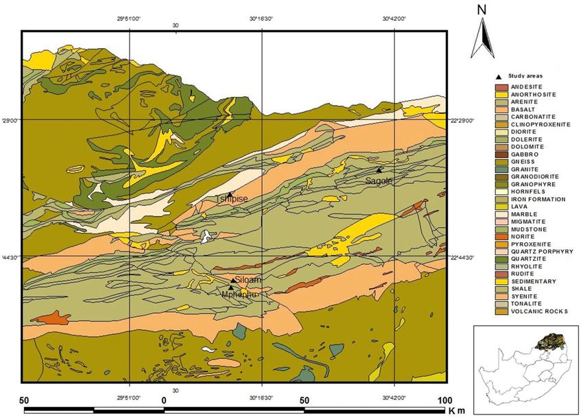
Geochemical classification of groundwater. Groundwater chemistry is directly linked to its quality
therefore it is imperative to understand the complex geochemical processes occurring below the surface of the
earth through different geochemical facies present. The Major cations (Ca2+, Mg2+, Na+ and K +) were plotted
against major anions (SO42-, HCO3- and Cl-) on a piper trilinear diagram, to understand the water type dominant
in the groundwater of Siloam (Fig. 3).
Piper diagram divides water into six basic types based on the dominating cation and anion. The divisions
are: (1) Ca-HCO3 type, (2) Na-Cl type, (3) Ca–Mg–Cl type, (4) Ca-Na-HCO3 type, (5) Ca–Cl type, and (6)
Na-HCO3 type63. From the piper diagram (Fig. 3), all the samples were plotted within the sodium chloride
(Na-Cl) quadrant. Na-Cl water type is dominated by N a+ and Cl- derived from Na-Cl which could be linked to
the underlying geology emanating from gneissic rocks. This water type is typical of marine and deeper ancient
groundwater influenced by ion exchange. Although exceptions can be made in situations where dissolution fac-
tors like residence time, climate and rainfall, are not favorable for fluoride migration from the rock to ground-
water as experienced in Eswatini K ingdom32.
Scientific Reports | (2021) 11:14000 | https://doi.org/10.1038/s41598-021-93385-4 7
Vol.:(0123456789)www.nature.com/scientificreports/
Figure 3. Piper Trilinear diagram of major anions and cations in Siloam groundwater (Figure drawn using GW
Chart version 1.30: U.S. Geological Survey Software Release, 26 June 2020, https://doi.org/10.5066/P9Y29U1H).
A previous study based on the water type of thermal groundwaters around Siloam area indicated that the
dominant water type is Na-Cl26,32. Groundwater mixing from different sources do not occur in the study area
because the water is predominantly and 100% N a+–Cl− type. A piper plot by D
urowoju64 shows that the geother-
mal springs of Siloam in both wet and dry periods were dominated by Na-Cl ions. Therefore, seasonal changes
do not significantly impact on the groundwater type and dominant cation and anions. However, groundwater
with high fluoride in Korea occurs mostly within the basement aquifer and are dominantly Na-HCO3 water type
influenced by granitoids and metamorphic rocks58. Elevated Na+ in groundwater could be from the weathering
and dissolution of plagioclase tectosilicate mineral end member (albite). Na–Cl water type indicates ancient
groundwater with ample residence time with associated overburden and aquifer material.
Gibbs diagram was used to further buttress the source of the Na enrichment. The Gibbs diagram gave a clear
indication that the groundwater enrichment was as a result of rock-water interaction and weathering (Fig. 4).
The total dissolved solids were plotted against major anions and cations on Gibbs diagram to determine the geo-
chemical process responsible for the chemical constituents of groundwater at Siloam using the Eqs. (1) and (2)65.
Cl
Anions = (1)
Cl + HCO3
Na + K
Cations = (2)
Na + K + Ca
However, the occurrence of Cl- > Na+ hydro-chemical process in borehole H1 (Table 2) denotes that although
a+—Cl-, the dominance of the water type is as a result of ion exchange and reverse
the prevailing water type is N
ion exchange. The occurrence of sulphate (SO42-) in groundwater is mostly assumed to be influenced by the
dissolution of gypsum or the neutralization of acid water by limestone or d olomite66. Gibbs plot showed the
geological process responsible for the mineralization process in the groundwater at Siloam.
The plot of Na/Cl (Fig. 5) is a good indicator of the type of weathering responsible for the dominance of Na in
groundwater. Mayback67 noted that Na/Cl ratio greater than one is an indication of silicate weathering, otherwise
the source of Na is from another source other than silicate weathering. From the Na/Cl ratio plot, 75% of the
samples (BH2, BH1 and H2) show predominant silicate weathering while 25% (H1) of the samples show other
a+ other than silicate weathering. This other source is the reverse ion exchange. The dominant N
sources of N a+
Scientific Reports | (2021) 11:14000 | https://doi.org/10.1038/s41598-021-93385-4 8
Vol:.(1234567890)www.nature.com/scientificreports/
100000
10000
Evapora on
TDS (mg/L)
1000
100
Rock-Water Interac on &
10
Precipita on
1
0 0.2 0.4 0.6 0.8 1
Cl/Cl+HCO3
A
100000
10000 Evapora on
1000
TDS (mg/L)
100 Rock-Water Interac on & Weathering
10
Precipita on
1
0 0.2 0.4 0.6 0.8 1
Na+K/Na+Ca+K
B
Figure 4. Gibbs plot showing dominant anion (A) and cation (B) mineralisation process of groundwater in
Siloam.
1.8
1.6 BH2 H2
BH1
1.4
1.2
1
Na/Cl
0.8
H1
0.6
0.4
0.2
0
0 1 2 3 4 5
Sample No
Figure 5. Plot showing Na/Cl ratio.
in the groundwater at Siloam is thus as a result of the weathering and chemical alteration of tectosilicate miner-
als in the form of Plagioclase feldspar (Na rich feldspar) or sheet silicate minerals in the form of chlorite, due to
rock-water interaction over a period resulting in base ion exchange between the rocks, soil and groundwater.
Chloro-Alkaline Indexes (CAI) were calculated from Eqs. (3) and (4) to determine if the N a+ is from base
ion exchange or from reverse ion exchange. In ion exchange process, the Ca and Mg from the groundwater
is exchanged with the N a+ and K + from the host rock or surrounding rocks. CAI 1 and CAI 2 were plotted in
Fig. 6a,b.
−
+
Cl Na + K +
CAI 1 = (3)
Cl
[Cl− − Na + + K + ]
CAI 2 = (4)
SO2− − 2− −
4 + HCO3 + CO3 + NO3
CAI 1 and CAI 2 will result in a negative value if the process of N a+ enrichment is by ion exchange process, oth-
erwise, the process of reverse ion exchange is r esponsible68. CAI 1 and CAI 2 from Fig. 6 shows that the boreholes
BH1, BH2 and H2 exhibited a sodium enrichment process by normal ion exchange while borehole H1 shows
that the sodium enrichment process is by reverse ion exchange process.
Scientific Reports | (2021) 11:14000 | https://doi.org/10.1038/s41598-021-93385-4 9
Vol.:(0123456789)www.nature.com/scientificreports/
a 0.4
H1
0.2
0
0 1 2 3 4 5
CAI 1
-0.2
-0.4
BH1
-0.6 BH2 H2
-0.8
Sample no
b 1.5
H1
1
0.5
CAI 2
0
0 1 2 3 4 5
-0.5 BH2
BH1
H2
-1
-1.5
Sample no
Figure 6. Chloro-Alkaline Index CAI 1 (a) and CAI 2 (b) for enrichment process.
Lithology and mineral composition of soils and rocks in the study area. The lithologic descrip-
tion of the samples is given in Table 4. Chlorite minerals can be found in any major rock group, but they are
known to be predominant in low grade metamorphic rocks. Chlorite is also the index mineral for green schist
facie69. Chlorite is found as a common constituent of igneous rocks resulting from hydrothermal alteration
of pyroxenes, amphiboles, biotite and garnet69. In sedimentary basins, Clay-rich sediments derived from the
weathering of igneous rocks are often rich in chlorite69. This is basically the source of chlorite enrichment in
sedimentary terrain.
The abundance of chlorite can be seen in Siloam which is made up of volcano sedimentary sequence. Table 5
gives the weight percent (wt.%) and the constituent minerals in all the soil and rock samples collected in Siloam
as analysed by X-ray Diffraction (XRD). The abundance of chlorite is seen especially in borehole cuttings of BH1
at depths 40–65 m where chlorite is seen as much as 38 wt.% of the total rock mass at some depths (Table 5).
However, the occurrence of chlorite determines the colour of the total rock mass given that the wt.% of chlorite is
more than 20% as seen in cuttings X40 and X65 (Table 5). From depths 5–35 m in borehole BH1, the pink–brown
colour could be due to the presence of smectite and occurrence of hematite. The brown colour may also be due
to the presence of plagioclase.
However, occurrences of quartz and muscovite mostly do not determine the colour of the whole rock mass
because they are mostly colourless to white in colour. The pinkish colour of rock SR2 could signify the occurrence
of hematite (iron oxide). The occurrence of chlorite in the sedimentary terrains of Siloam and the high abundance
of smectite and hematite group shows that the present geologic sequence has undergone a series of weathering
and tectonic activities. This explains the abundance of Na+ in groundwater at Siloam because of ion exchange and
possible reverse ion exchange during the process of weathering of silicate minerals like plagioclase and chlorites.
From the mineralogy (Table 5), silicate minerals as well as clay minerals are abundant in the study area. The
area is dominated by clay minerals such as chlorite and smectite, as well as silicate minerals such as muscovite,
biotite and plagioclase. Clay can adsorb and desorb fluoride under favorable condition. Clay in the soil can func-
tions as a natural barrier to protect groundwater from fluoride pollution due to its strong adsorption p otential70.
The adsorption capabilities of clay are possible in the acidic pH conditions. However, the adsorbed fluoride ion
can also be released into the groundwater under alkaline conditions.
The adsorption properties of fluoride by clay are proportional to the amount of clay minerals present. Clay
desorption is a faster geochemical process when compared to adsorption process71, thus it is easy for fluoride to
migrate from clay to groundwater when in contact with small volume of alkaline water. The abundance of clay
minerals show that extensive weathering altered the chemical and physical composition of the silicate minerals to
form clay minerals. The fluoride enrichment of the groundwater in the area is as a result of ion exchange between
the fluoride bearing minerals and groundwater. However, muscovite also contains fluoride as an accessory ion
in its chemistry, which at favorable conditions, is released into the groundwater.
Scientific Reports | (2021) 11:14000 | https://doi.org/10.1038/s41598-021-93385-4 10
Vol:.(1234567890)www.nature.com/scientificreports/
Location Sample ID Depth (M) Associated group Lithology Brief description
S1 Soil Clay Brown color with very fine texture
This rock type shows a low-grade metamorphism
S SR2 Metamorphic Epitomized grey wacke characteristic and it exhibits an aphanitic texture. It has a green colour due to the abun-
dance of chlorite
SR3 Sedimentary Sandstone Pinkish Sandstone due to the presence of hematite
Topsoil with brittle texture and pinkish-brown color. Presence of Smectite and hematite
X5 5 Sedimentary Argillaceous Sediment
noticeable
X15 15 Sedimentary Argillaceous Sediment Dark brown color with reduced pinkness probably due to the hematite content
X20 20 Sedimentary Argillaceous Sediment Light pink color due to the heavy presence of clay mineral Smectite and Hematite
BH1
Reduction in the pink color and traces of darker brown color. Smectite and Hematite still
X30 30 Sedimentary Argillaceous Sediment
present although at a reduced concentration
Green in color probably due to the presence of Chlorite mineral and the rock is slightly
X40 40 Sedimentary Gray Wacke saturated due to its function being the aquifer rock. Total disappearance of clay minerals of
smectite and hematite
Green in color probably due to the presence of Chlorite mineral and the rock is slightly
X65 65 Sedimentary Gray Wacke saturated due to its function being the aquifer rock. Total disappearance of clay minerals of
smectite and hematite noticeable. Index mineral noticed are quartz and chlorite
Y5 5 Soil Clay Light brown in color with more than 60 wt.% Smectite
Y10 10 Soil Clay Light brown color with increased smectite content of more than 70 wt.%
BH2 Reduced lightness with two different groups of Smectite namely smectite 1 and 2. Overall
Y20 20 Soil Clay
smectite content is greater than 75 wt.%
Dark brown color with intercalation of clay and sand. Although smectite content is still
Y25 25 Soil Sandy Clay
above 50% but there is reduction in its wt.%
Y28 28 Igneous Basalt Dark color with dominantly plagioclase feldspar and diopside mineral
Y40 40 Igneous Basalt Dark color with dominantly plagioclase feldspar and diopside mineral
Table 4. Lithologic Description of Sampled Rocks and Soils. S surface soil, SR surface rocks, BH1 borehole 1,
BH2 borehole 2.
S1 SR2 SR3 X5 X15 X20 X30 X40 X65 Y5 Y10 Y20 Y25 Y28 Y40
Weight (%)
Diopside 2.76 20.5 28.7 29.87
Chlorite 28.41 4.21 5.42 4.59 5.42 38.92 26.98 4.69 4.72
Hematite 1.7 0.17 0.67 9.41 7.87 5.07 7.27 0.78
Muscovite 1.6 32.41 33.77 33.07 41.15 12.33 7.49 4.56 3.29
Orthoclase 8.04 2.65 1.87 7.7 5.61 7.97 14.99
Plagioclase 32.38 14.82 17.35 16.31 11.08 6.86 9.75 22.93 39.49 38.27
Quartz 8.36 14.47 97.73 35.99 34.44 44.76 30.04 25.99 20.72 12.19 8.34 5.53 9.72 7.69 9.00
Smectite 44.26 15.33 16.63 12.51 16.1 69.02 78.41 52.36 5.88 7.1
Smectite1 41.2
Smectite 2 35.55
Sepiolite 2.49
Epidote 21.63 12.04
Titanite 5.4 7.25
Actinolite 9.22 2.08 2.6
Enstatite 3.02
Ilmenite 3.89 5.18
Table 5. Mineral constituents and percentage weight of rocks and soils. S surface soil, SR surface rock, X
borehole BH1 depth, Y borehole BH2 depth
Muscovite is an important fluoride bearing mineral because it contains fluorine in its crystal lattices and
hydroxyl groups which can also substitute for fluoride because of their similar ionic c harges70. This fluorine can
be released as fluoride ion into the groundwater under favorable conditions. Muscovite occurs at about 1.62 wt.
% (Table 5) in SR3. O nipe48 noted that muscovite in the surface rocks at Siloam contributes to the groundwater
fluoride rather than fluorite as earlier inferred by McCaffrey and Willis25 and Odiyo and Makungo35. Onipe48
also argued that the muscovite present in the surface sandstone at Siloam can never be the sole contributor of
fluoride to groundwater of the area.
Surface rock SR2 contains high proportions of chlorite and epidote (Fig. 6). The occurrence of clinochlore,
an end member of chlorite is predominant in Siloam. Chlorite has been linked to fluoride contribution to
Scientific Reports | (2021) 11:14000 | https://doi.org/10.1038/s41598-021-93385-4 11
Vol.:(0123456789)www.nature.com/scientificreports/
0 5 10 15 20 25 30 35 40 45
Chlorite
X40
12300
Quartz
Intensities (Count)
8200 Chlorite
Chlorite
4100 Muscovite
Muscovite Plagioclase
Plagioclase
0
Chlorite X65
13500 Chlorite
Intensities (Count)
Quartz
9000
4500 Epidote Plagioclase
0
0 5 10 15 20 25 30 35 40 45
2-theta (Degrees)
A B C
Figure 7. XRD plot showing major minerals in borehole 1 at X15, X20 & X30 (A) and surface soil SR2 & SR3
(B) borehole 1 at X40 and X65.
groundwater mostly due to its hydroxyl content which is displaced by fluoride ion. Generally, chlorite contains
fluoride but not as much as its ripidolite. This reason is attributed to the fact that clinochlore has an appreciable
number of aluminium in its octahedral layer therefore limiting its fluoride adsorption properties unlike ripidolite
that has aluminium in its tetrahedral layer. However, at varying depth in borehole BH1, muscovite occurs as an
abundant rock forming mineral rather than its accessory form as found in SR2. The concentration of muscovite
in wt. % increases from topsoil to 30 m below the surface (Table 5). The major minerals present in borehole
BH1 from depth 5 m to 30 m are muscovite, quartz and smectite (Table 5). The abundance of major dominating
minerals of borehole BH1 from depth 15–30 m are shown in Fig. 7. Fluorine affiliated muscovite increases with
depth from 5 to 15 m, slows down at depth 20 m and picks up its increasing trend again at depth 30 m below
ground level before drastically reducing as the depth increases.
Figure 7C shows the XRD peaks for the epitomized gray-wacke which is the aquifer rock for borehole BH1.
Although muscovite is present, the abundance is not as much as at depths 5 to 30 m. The grey wacke is dominated
by chlorite which explains why the color is greenish grey (Table 4). The primary minerals present in the rock
materials include chlorite, quartz and plagioclase. The intensities and abundance of each mineral are identified in
Fig. 7. The combined presence of muscovite and chlorite at depth X40 and X 65 in borehole BH1 may accounts for
the slightly high total fluoride concentration of the aquifer due to the exchange of OH with F in their structure.
Figure 7 also shows a high abundance of plagioclase which denotes that the level of weathering is either absent
or low at depth 40 m below the earth surface, therefore there has been no chemical alteration of plagioclase to
smectite clay or kaolin as seen at shallow depths before 40 m. Two main dynamic geochemical processes occur
in clay, they are the enrichment and leaching processes. Under the dynamic geochemical process of leaching,
areas with clay formations and arid to semi-arid climatic conditions, experience high groundwater and surface
water fluoride c oncentration72. Dynamic geochemical process of leaching occurs when fluoride is leached out
of clay formation into groundwater through infiltration and percolation of water. Fluorine can easily migrate
from clay formations to groundwater during migration of g roundwater73.
In borehole BH2 at Siloam, muscovite which is the predominant fluoride bearing mineral in the area is seen
to be absent until the depth of 28 m (Table 5). Muscovite occurrence was found at depth 28 to 40 m although at
a volume less than 5 wt.%. The peaks of smectite at depths Y5, Y10, Y15 and Y20 occur at almost the same count
and intensity (Fig. 7). Smectite is the most abundant mineral at depths Y5–Y20. Clay could also act as a migration
agent for fluoride enrichment of groundwater at Siloam. The abundance of major minerals in borehole BH2 at
depths Y28 and Y40 are also described in Table 5. The abundance of chlorite and plagioclase were also revealed
from the results. Y28 and Y40 is the basaltic aquifer material of borehole BH2.
Chemical composition of rocks and soils in the study area. In sedimentary terrain, the most abun-
dant fluorine bearing mineral is associated with mica mineral group and clay minerals especially montmoril-
lonite and kaolinite. Total rock chemistry is important to determine the total rock composition in oxides and
elemental properties. The graphical representation of major oxides in the rocks and soil of Siloam are presented
in Fig. 8. The rocks and soil are dominated by high silica content followed by aluminium oxides. The highest
concentration of silica occurs at surface sandstone rock of location SR3. The formula for conversion of oxides to
elemental weight. percent is given in Eq. (5).
Scientific Reports | (2021) 11:14000 | https://doi.org/10.1038/s41598-021-93385-4 12
Vol:.(1234567890)www.nature.com/scientificreports/
CaO Na₂O MgO Al₂O₃ SiO₂ P₂O₅ K₂O MnO Fe₂O₃
120
100
80
Major Oxides in wt.%
60
40
20
0
S1 SR2 SR3 X5 X15 X20 X30 X40 X65 Y5 Y10 Y20 Y25 Y28 Y40
Sample ID
Figure 8. Major oxide abundance in sampled rocks and soils.
Oxide wt percent × Conversion factor = Elemental wt percent (5)
The conversion factor is the sum of the atomic weights of the elements in the required formula divided by
the sum of the atomic weights in the original formula. Silica (SiO2) and quartz (SiO2) have the same chemical
composition, but they are different in nature. Silica refers to the total pure silicon dioxide in the rock mass while
quartz refers to a mineral with a very high concentration of silica. However, often, quartz occurs as silica with
little amount of impurities. Therefore, the name is used interchangeably. Total rock silica could be from quartz
and other silicate minerals like feldspars, chlorites and other aluminium and silicate rich minerals. The SiO2
refers to the total silica content of the rock and soil. Silica has the highest wt. % in soils and rocks of Siloam. This
means that the area is dominated by felsic rock and the soil with high silica content. Felsic rocks, which contain
relatively high concentrations of S iO2, tend to have higher concentrations of fluorine than mafic r ock74.
Table 6 shows the total major elemental and fluorine compositions of rocks and soils at Siloam in mg/kg.
Although fluorine is regarded as a trace element, its concentration in some rocks and soil in Siloam is higher
than expected. The total fluorine content of rocks and soil ranges from 10 to 2000 mg/kg (Table 6). The average
fluorine concentration is about 762 mg/kg. This is above the permissible limit of 30 mg/kg concentration of
fluorine in soil for agriculture75. The highest fluorine concentration of 2000 mg/kg occurs at a depth of 5 m in
borehole BH2. The lowest concentration occurs in borehole BH1 at a depth of 30 m (Table 6).
The fluorine concentration in clay is typically in the range of 20–500 mg/kg76. The surface clay deposit S1 has
a total fluorine concentration of 431 mg/kg (Table 6). However, the clay formation of borehole BH2 from 5 m to
around 20 m depth has the highest concentrations of fluorine. The Soil of BH2 at depths 5 m and 10 m have more
fluorine concentration than the surface rock formations and aquifer rocks in Siloam as observed from Table 6.
This is different from the findings of McCaffrey and W illis25 that stated that rock samples have higher fluorine
content than soil samples. The clay deposit and argillaceous sediments of Siloam are from chemical alteration
and weathering of plagioclase of parent rock materials therefore giving more room for OH and F replacements.
This ion displacement gives a higher room for more storage of fluoride in the crystal lattices of the resultant clay.
It should be noted, however, that clays formed under hydrothermal conditions are mostly rich in fl uoride77 as
observed in Siloam, although this is not always the case as observed in Sagole, Tshipise and Evangelina area of
Limpopo, South A frica78.
Fluoride leaching and other chemical constituents from rocks and soils. The fluoride concentra-
tion emigrating out of the rock and soil samples of Siloam ranges from 0.27 to 14.88 mg/L (Table 7). Leachate
with the lowest fluoride concentration occurs at surface rock SR2 and leachate with the highest fluoride concen-
tration occurs at a depth of 5 m of borehole BH2 (Table 7). Fluoride concentrations show a decreasing trend from
the surface down to the aquifer. Figure 9 shows the fluoride concentration trend in the borehole BH1 leachates.
The fact that from boreholes BH1 and BH2, the sub-surface rocks and soils of Siloam show decreasing trends
in fluoride concentrations, means that the aquifer rocks release less fluorine into the groundwater compared to
the regolith and overburden soils and clays. This may partially be due to the loose state of the overburden. The
ions in the leachate were correlated against each other to determine the relationship between them in relation to
Scientific Reports | (2021) 11:14000 | https://doi.org/10.1038/s41598-021-93385-4 13
Vol.:(0123456789)www.nature.com/scientificreports/
Sample ID Ca Na Mg Al Si P K Mn Fe F
S1 25,429.08 23,889.18 21,587.40 90,880.81 241,417.00 3500.73 11,206.35 1541.26 95,607.98 431.00
SR2 58,286.88 20,253.87 48,240.00 87,863.80 225,241.50 969.03 305.48 1657.43 101,972.52 1400.00
SR3 415.72 242.60 940.68 12,650.27 448,332.50 484.52 3137.78 41.82 6329.57 160.00
X5 658.58 5749.73 20,019.60 100,461.14 271,477.25 281.54 33,619.05 569.26 91,551.46 450.00
X15 2021.47 2559.56 22,672.80 102,101.97 271,617.50 471.42 33,536.04 723.38 86,096.14 330.00
X20 2521.48 1409.61 21,406.50 94,744.70 296,628.75 475.79 35,030.22 749.72 62,806.12 290.00
X30 4057.22 1468.96 23,215.50 108,877.01 264,231.00 659.12 43,580.25 836.46 79,941.42 10.00
X40 14,143.14 10,757.55 59,094.00 103,848.66 231,926.75 1169.82 11,621.40 1773.61 97,706.18 850.00
X65 36,000.72 11,944.59 54,330.30 88,340.17 232,815.00 999.59 11,123.34 1618.71 100,084.14 770.00
Y5 13,500.27 10,905.93 29,486.70 86,911.06 267,129.50 2330.91 8301.00 1184.99 91,551.46 2000.00
Y10 13,785.99 12,389.73 27,376.20 85,587.81 265,166.00 2099.57 8633.04 1239.20 95,188.34 1500.00
Y20 17,143.20 8457.66 26,954.10 97,444.13 260,163.75 2549.16 10,210.23 1215.97 89,872.90 1200.00
Y25 31,214.91 14,021.91 24,602.40 86,805.20 255,442.00 3727.71 17,017.05 1394.10 87,145.24 800.00
Y28 51,572.46 20,847.39 29,124.90 82,041.50 239,593.75 4932.45 19,922.40 1014.60 74,695.92 620.00
Y40 54,429.66 19,437.78 31,959.00 76,960.22 236,181.00 4234.05 16,851.03 1177.24 81,340.22 620.00
Table 6. Major elemental compositions of rocks and soils (mg/kg) in the study area. S surface soil, SR surface
rock, X borehole BH1 depth, Y borehole BH2 depth, ion units, mg/kg depth: m.
K EC pH Ca Mg Cl NO3 NO2 PO4 Na B F
Sample mg/kg µs/cm mg/kg mg/kg mg/kg mg/kg mg/kg mg/kg mg/kg mg/kg mg/kg
S1 62.50 24.00 7.57 135.00 891.00 36,03 1,65 0.00 1,89 929.00 1.75 10,52
SR 2 11.60 3.00 7.17 BDL 40.00 2,75 0,12 0.00 0,67 36.10 0.05 0,27
SR 3 27.80 3.00 6.83 BDL BDL 2,77 0,21 0.00 3,17 2.26 0.04 0,44
X5 379.00 42.00 7.10 19.80 773.00 114,43 24,66 0.00 1,55 1020.00 2.07 3,85
X 15 125.00 7.00 6.91 2.26 172.00 10,59 2,41 0.00 0,78 110.00 0.46 2,29
X 20 118.00 3.00 6.95 1.88 150.00 2,15 0,60 0.00 0,65 52.40 0.28 1,10
X 30 164.00 3.00 7.03 11.90 183.00 1,61 0,72 0,03 0,59 35.90 0.38 0,78
X 40 33.40 4.00 7.16 18.20 179.00 1,43 0,58 0,13 0,30 72.00 0.26 0,68
X 65 31.90 9.00 7.37 36.30 41.20 2,34 0,56 0,71 0,50 82.40 0.02 0,53
Y5 31.90 32.00 8.00 186.00 675.00 11,57 0,78 0.00 0,39 886.00 0.93 14,88
Y 10 45.60 76.00 7.97 145.00 438.00 171,79 8,10 0.00 1,00 1620.00 1.11 9,51
Y 20 26.00 6.00 7.16 68.00 178.00 2,12 0,85 0.00 0,39 129.00 0.26 3,79
Y 28 61.90 9.00 7.43 94.80 97.90 1,93 0,29 0,33 0,90 151.00 0.15 1,02
Y 25 25.30 5.00 7.10 19.30 61.60 1,59 0,15 0,01 0,70 84.20 0.14 2,60
Y 40 54.50 10.00 7.50 110.00 104.00 2,46 0,27 0,49 0,80 166.00 0.17 0,72
Table 7. Chemical parameters in the leachate obtained from leaching experiment. BDL Below detection Limit,
S surface soil, SR surface rock, X borehole BH1 depth, Y borehole BH2 depth
the release of fluoride. Table 8 shows the correlation coefficients in the leachate at Siloam. Fluoride concentrations
in groundwater of boreholes BH1 and BH2 show high positive correlations to pH, Ca, Na (Table 8).
This means that at an increasing F concentration, pH, Ca and Na increases. The concentrations of these
highlighted parameters (pH, Ca, Na) are directly proportional to each other. EC is also positively correlated
to F, which means that increase in fluoride results in an increase in pH, Ca and Na which in turn increases the
conductivity of the groundwater of boreholes BH1 and BH2. The very weak correlation between fluoride and
nitrate confirms that the possible source of high nitrate in groundwater of BH2 is not from a natural source rather
from anthropogenic sources which were previously inferred.
The weak negative correlation between fluoride and potassium connotes that most of the occurrence does not
originate from K bearing minerals. The groundwater fluoride of the study area is controlled by the desorption and
adsorption properties of clay and partly by chlorite. Therefore, the groundwater hydrochemistry is dominated
by Na-Cl water type signifying the importance of Na weathering and dissolution to investigating groundwater
fluoride source. The process is simplified by Eq. (6).
NaAlSiO8 + 2H + + 9HO → AlSiO5 (OH) + 4HSiO + 2Na (6)
The hydroxyl ion in the clay is displaced by fluoride in the structure lattice of the kaolin-smectite clay due
to the similarity in their charge and radius. The resultant Na in the equation explains the abundance of Na in
Scientific Reports | (2021) 11:14000 | https://doi.org/10.1038/s41598-021-93385-4 14
Vol:.(1234567890)You can also read