Manchester Street Water Mains, Christchurch: Report on Archaeological Monitoring - SCIRT ...
←
→
Page content transcription
If your browser does not render page correctly, please read the page content below
Lessons learned from one of New Zealand’s most challenging civil engineering projects:
   rebuilding the earthquake damaged pipes, roads, bridges and retaining walls in the city of
   Christchurch 2011 - 2016.

Manchester Street Water Mains, Christchurch:
Report on Archaeological Monitoring

Story:         Archaeology
Theme:         Programme Management

A report which details the archaeological investigations carried out during the course of SCIRT
project 11185, water main renewal work on Manchester Street.

  This document has been provided as an example of a tool that might be useful for other
 organisations undertaking complex disaster recovery or infrastructure rebuild programmes.

       For more information about this document, visit www.scirtlearninglegacy.org.nz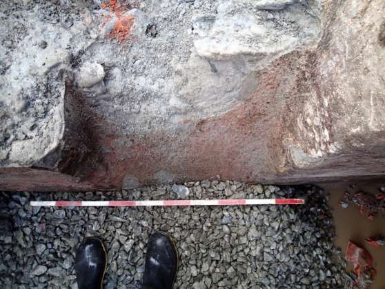
MANCHESTER STREET WATER MAINS, CHRISTCHURCH: REPORT ON
              ARCHAEOLOGICAL MONITORING
                                     NZHPT AUTHORITY 2012/321EQ

                                               SCIRT 11185

                 HAMISH WILLIAMS, CHRISTINE WHYBREW, JILL HALEY & MARIA LILLO BERNABEU
                              UNDERGROUND OVERGROUND ARCHAEOLOGY LTD

                                             SEPTEMBER 2016

               UNPUBLISHED REPORT FOR MCCONNELL DOWELL AND CHRISTCHURCH CITY COUNCIL

INTRODUCTION
Subsequent to the earthquake on 22 February 2011, water supply pipes in Christchurch were
damaged, necessitating replacement. On 26 September 2011 New Zealand Historic Places Trust
(NZHPT) issued a global authority (2012/321eq) under section 11 of the Canterbury Earthquake
(Historic Places Act) Order 2011 to the Christchurch City Council. This authority was issued to allow the
council, in conjunction with the Stronger Christchurch Infrastructure Rebuild Team (SCIRT), to
undertake various earthworks in Christchurch. An authority was required as these earthquake related
infrastructure repair works had the potential to impact upon known or unknown archaeological sites.
During the course of excavations on Manchester Street for a new water mains pipe, two archaeological
features were uncovered – a 19th century rubbish deposit in an infilled gully or river channel, and a fire
tank reservoir constructed in 1885 (Figure 1 and Figure 2). This report details the archaeological
investigations of these features that took place during the course of SCIRT project 11185.

Figure 1 . Central Christchurch, showing the location of the new Manchester Street water mains pipe as shown
with red line. Image: Google Maps.

                                                     1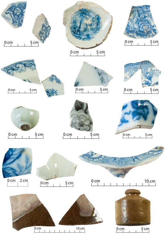
Figure 2. 2016 aerial imagery of the Manchester/Gloucester Street intersection and environs, showing the
location of the two archaeological features uncovered during July 2015 excavations for the new Manchester
Street water mains pipe. Image: Canterbury Maps.

ARCHAEOLOGICAL MONITORING OF EARTHWORKS
Excavations for the installation of approximately 600 m of 300 mm diameter water mains pipe on
Manchester Street (between Armagh Street in the north and Lichfield Street in the south) took place
from July to October 2015, with Trenching Dynamix as the main earthworks and pipe installation
subcontractor. Located along the eastern side of the Manchester Street roadway, this trench was
approximately 1.2 m wide and excavated to 1.5 m depth. Two features were uncovered during the
course of this work: Feature 1, a 19th century rubbish deposit in an infilled river channel/gully; and
Feature 2, an 1885 fire tank reservoir. Both of these features were located close to the
Manchester/Gloucester Street intersection, and both were investigated by Hamish Williams from
Underground Overground Archaeology from 27 July to 3 August 2015 (Figure 3).

                                                   2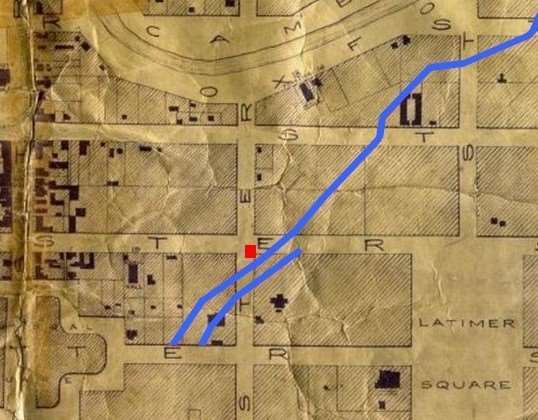
Figure 3. Plan showing the location of the two features uncovered on Manchester Street, and the locations of
the stratigraphic profile drawings.

                                                     3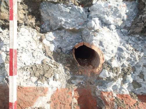
FEATURE 1: THE AVON RIVER CHANNEL

Historical background 1
Christchurch was laid out on a large swampy area of the Canterbury plains. The original town plan,
plotted by Edward Jollie in 1850, was laid across the Avon River, taking advantage of this means of
water supply and drainage. Inevitably the tributaries and overflow channels associated with the river
ran through the streets and town sections surveyed on either side of the river, resulting in serious
drainage problems (Wilson 1989: 10-11). Jollie’s plan, known as the ‘Black Map’, indicates that a major
channel ran through the city between the Avon River and the edge of Cathedral Square (Figure 4).

Figure 4. Detail of Jollie’s 1850 ‘Black Map’ showing the original platting of Christchurch and the course of the
channel between the Avon River and the edge of Cathedral Square (red dotted line). Image: Jollie 1850.

In the early years of the city, the Canterbury Provincial Council attempted to address the drainage
issue by establishing two major stormwater drains, on Moorhouse Avenue and Ferry Road. These were
accompanied by smaller pipe, brick and open drains emptying into the Avon River. When the
Christchurch Municipal Council was established in 1862, it immediately commissioned a report on
necessary improvements to surface drainage and other sanitary issues. The sanitary committee made
the following recommendations with regard to the filling and levelling of streets and associated
hollows:
       The surveyor should be particularly directed to form all the streets, where possible, at a level
       below that of the adjoining sections. If no immediate use be found, by filling up gravel pits or
       adjoining hollows, for the surplus earth from the streets thus formed, it should be temporarily
       deposited in the squares or other open places.

       Your committee are of the opinion, that by alteration of the Municipal Council Ordinance, you
       should be empowered to fill up hollows on private property, in which the accumulation of
       stagnant water is likely to produce disease, and to recover the cost of doing so from the occupiers
       or owners of property.
                 Press 30/8/1862: 4.

1
 Online primary source material was consulted in the preparation of this narrative. This included deeds, maps,
newspapers, electoral rolls and city directories. These sources were supplemented with published and
unpublished secondary sources on drainage.

                                                        4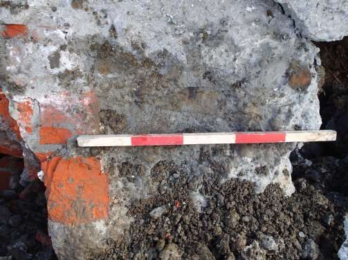
The council initiated a programme of street levelling (to minimise water stagnation) and the
installation of open and pipe drains emptying into the rivers and creeks of the city (Wilson 1989: 14).
In 1864 the City Surveyor, W. F. Moore, presented a report to the council on the drainage of the city.
It was noted that the “rapid occupation of the sections and the formation of the streets” had dammed
up the original channels and gullies that had provided the main drains. He made recommendations for
a drainage system that included kerbs and side channels to the streets and the installation of drain and
sewer pipes. He described the open ditch drains, which were located primarily in the least populated
areas of the city, as “indispensable” but acknowledged that they would eventually need to be made
covered drains (Press 19/7/1864: 2).
Part of the channel indicated on Jollie’s map was located near the archaeological site at the
intersection of Manchester and Gloucester streets. In 1902, a Canterbury colonist reminiscing about
his childhood in early Christchurch described this section of the ‘old gully’ as it ran between Cathedral
Square and Gloucester Street: “it ran its course through the buildings now occupied by Dalgety and
Co. and the Tram Co., and entered the garden of the Late Judge Gresson, opposite the Canterbury Hall.
Its course was then through the present City Council’s yard” (Press 12/6/1902: 4). He also described
“ponds” that formed in the channel that were filled with raupō. These ponds were likely to have been
pools of stagnant rainwater, and combined with rubbish that would have accumulated in them, posed
serious health hazards, and water-borne diseases such as typhoid, diphtheria and dysentery took their
toll. By 1870 Christchurch had the highest death rate of any urban centre in New Zealand (Wilson 1989:
16).
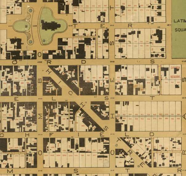
The 1862 and 1877 maps of Christchurch show that few buildings were erected in the vicinity of the
channel (Figure 5 and Figure 6). It seems likely that the problems with drainage deterred development
of many of the nearby sections.
Figure 5. Detail from the 1862 map of Christchurch showing the channel (blue lines), the location of the Feature
1 rubbish deposit at the intersection of Manchester and Gloucester streets (red square) and the absence of
development near the channel. Image: Fooks 1862.
5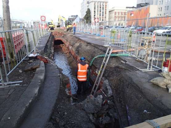
Figure 6. Plan of Christchurch from 1877 showing the channel (blue lines), the location of the Feature 1 rubbish
deposit at the intersection of Manchester and Gloucester streets (red square) and the absence of development
near the channel. Image: Strouts 1877.
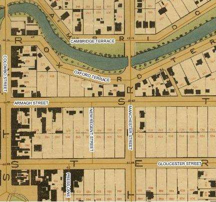
Development of the town sections south of Gloucester Street along Manchester Street took the
channel into consideration and gardens were built in the problematic areas (Figure 7). Two acres
(comprised of Town Sections 680 to 687) were owned by John Bealey but leased out to tenants during
the 1860s and 1870s (LINZ 1850: 680, 681, 682, 683, 684, 685, 686, 687). The property was called ‘The
Pines’, and had a large house located away from the site of the old channel (Star 28/12/1868: 1).
Among the occupants was the Mayor of Christchurch, Henry Sawtell, who lived there in the early 1870s
(Press 13/3/1872: 2) Town Sections 688-694 were owned by Rose in the 1850s and 1860s, and a large
house was built at the corner of Worcester and Manchester streets and the remaining land made into
garden (LINZ 1850: 688, 689, 690, 691, 692, 693, 694). The property was occupied by Justice Gresson
until 1867 when John E. Coker took it over and turned it into a boarding house (Lyttelton Times:
1/7/1867: 3). The garden was open to the public and described in an advertisement as “laid out in a
superior manner, with expensive shrubs and trees, having shady nooks and delightful walks, and
forming a beautiful retreat” (Lyttelton Times 9/5/1867: 3). Coker did extensive work on the property,
filling in the “stagnant pool of water which used to lie in what was once an old arm of the Avon” and
laying lawn in its place (Press 5/10/1867: 2).
6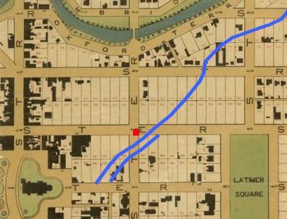
Figure 7. Development of town sections near the channel (outlined in blue) showing Coker’s Hotel and Garden
(outlined in green), ‘The Pines’ (outlined in yellow), and the location of the Feature 1 rubbish deposit (indicated
in red). Image: Strouts 1877.

Although Coker fixed the issues with water on his grounds, the poor condition of the drains beyond his
property continued to cause problems. On 7 January 1868, Christchurch was hit with a severe
thunderstorm. For nearly half an hour there was a downpour that included three minutes of hail, and
within minutes of the heavy rain starting, the sides of the streets were “filled with bounding torrents”.
The newspaper report of the event commented, “There is nothing like a good smart shower for finding
out the weak points in the drainage of the city” (Lyttelton Times: 8/1/1868: 2). The side channel along
Gloucester Street between Colombo and Manchester streets was identified as being particularly poor,
and the report described in detail the problems it caused Coker:
         This side channel, from the fact that it is neither deep enough nor wide enough, and from the
         additional fact that it is or was thoroughly choked up with a luxuriant crop of grass, was
         altogether unequal for the emergency; the consequence was that the water was thrown back
         on to the grounds attached to Coker’s Hotel. A few months ago Mr Coker, at a very
         considerable expense, was compelled to fill up the old riverbed in his grounds, which many will
         remember as a stagnant pool of the very filthiest description. The imperfect drainage of the
         city in the spot we have referred to has been the cause of considerable damage to Mr Coker.
                   Lyttelton Times 8/1/1868: 2.

A month later Christchurch was hit with a bigger disaster when the Waimakariri River flooded on 3 and
4 February 1868. The Avon rose quickly, and within hours had breached its bank near the Madras
Street bridge. Two hours later it flowed onto Gloucester Street (Lyttelton Times 5/2/1868: 2).

During 1868 the council worked at alleviating the problems with drainage and installed drain pipe
culverts around many parts of the city. This included the particularly problematic intersection of
Gloucester and Manchester streets as well as the junction of Manchester Street and the south drain,
where a double row of 15 inch pipe drain was laid (Star 15/12/1868: 3).

In the 1870s the council adopted a new culvert design. Although a general improvement on the old
style, the “gross carelessness” with their construction meant some were not draining properly. In 1876
a culvert built at the intersection of Gloucester and Manchester streets was found to be 7 inches out
of line with the Manchester Street channelling at one end and over 3 inches deeper in the centre than
at the outfall end. When water in the centre exceeded 3 inches, there was no flow (Star 27/10/1876:
2).

                                                        7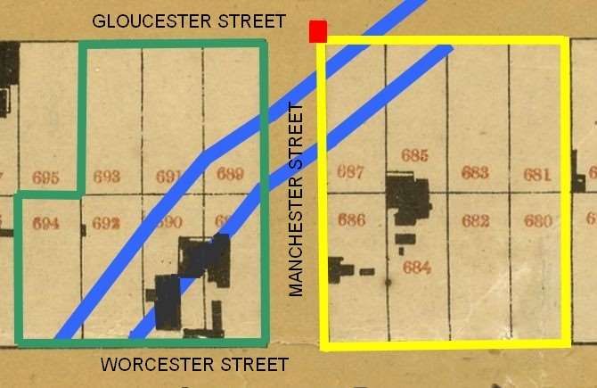
Drainage continued to be a problem at that intersection until the end of the century. In 1896 a letter
was sent to the Press complaining about the state of a drain flooded with soapsuds that was stagnant.
It was, according to the writer, “the most gruesome death trap as to stench it has ever been my ill fate
to know. I fear we may hear of an abundance of typhoid and gastric fever, also diphtheria, if allowed
to remain” (Press 17/10/1896: 5).

Archaeological monitoring
Feature 1 was a 19th century rubbish deposit that was exposed by hydro excavation at a depth of 1350
mm below the road surface, and comprised a concentration of artefacts within a layer of compact grey
clay (Figure 8, Figure 9 and Figure 10). These artefacts were distributed across a 2.4 metre long stretch
of the trench, and the artefact-bearing grey clay was capped by six successive layers of grey clay, some
of which were ash or soot stained (Figure 11 and Figure 12). A stratigraphic profile drawing of part of
the west baulk of the trench was produced, but because of time constraints and health and safety
considerations (owing to instability of the east baulk caused by the hydro excavation) only a 650 mm
long section of the baulk was able to be drawn (Figure 13). Up to 250 mm of this base grey layer that
contained the artefacts was excavated by hand until the required 1500 mm depth was reached. The
bottom of this artefact-bearing layer was not reached during the course of this work, and as such
artefacts from this feature remain in situ in this location below 1500 mm, as well as east and west of
this location outside the trench line. The location of this rubbish deposit and the depth at which it was
uncovered suggests that this material had been deposited in a low spot in the roadway either prior to,
or during the course of 19th century road formation works. These works would have involved infilling
(either in whole or in part) the natural gully or channel that crossed the roadway in this location. As
such, this rubbish bearing deposit can be defined as a surface accumulation or ground levelling fill
(after Butcher and Smith 2010: 56). Diagnostic artefacts from this feature were recovered for further
analysis.

Figure 8. Looking northwest across the hydro excavated section of water mains trench as it crosses the
Manchester/Gloucester Street intersection.

                                                   8
Figure 9. The Feature 1 rubbish deposit as first exposed near the base of the hydro excavated section of trench.
The concrete bedded 225 mm diameter Gloucester Street earthenware sewer mains (installed 1905) is visible
crossing the trench at far right of image.
Figure 10. Looking westwards along Gloucester Street at the Manchester Street intersection, with the water
mains trench in the foreground. The spatial extent of Feature 1 exposed in the trench is indicated with the
dashed white line.
9Figure 11. Feature 1 at a depth of 1400 mm, showing animal bones, glass, and ceramic in the compact grey
clay layer.
Figure 12. The western baulk of the excavation at the location of Feature 1. Note the rubbish deposit at base
of trench, lower left of the photograph, and the ash/soot stained clay layers capping the deposit.
10Figure 13. Stratigraphic profile drawing of part of the western baulk of the trench, at the location of the feature
1 rubbish deposit.
Artefact analysis
A total of 76 artefacts, from 139 fragments, were recovered from Feature 1, the artefact deposit in the
infilled channel/gully. These included ceramic, faunal, glass, metal and other items (Table 1). Items
were initially classified according to material class (ceramic, faunal, glass, metal, miscellaneous, shoes)
before being identified to individual types and forms. Details of the analytical methods used during
this process are provided in Appendix 1. The assemblage was then quantified by the number of
individual specimens present (NISP), from which a minimum number of vessels (MNV) or individuals
(MNI) was calculated (there is a full list of the artefacts in Appendix 2).
Table 1. Total NISP and MNI of artefacts from Manchester Street Water main, listed according to material.
Material NISP MN
Ceramic 55 29
Faunal 33 27
Glass 10 8
Metal 21 4
Miscellaneous 9 4
Shoes 11 4
Total 139 76
11Ceramic
A total of 29 ceramic vessels, represented by 55 fragments were found in Feature 1. These consisted
primarily of tea and table wares. The tea wares included two saucers and five teacups, while the table
wares comprised eight plates, one dinner plate, one side plate, one egg cup, two jars, two unidentified
hollow-ware vessels and one platter. Household items were also recovered, in the form of two
chamber pots and one ink bottle. In addition, two fragments of a coarse earthenware bowl were found
(Table 2 and Figure 14).
Table 2. Ceramic vessels recovered from the site, listed according to body type, ware type, functional class and
artefact form.
Body Type Ware Function Form MNI
ew-c sgst household bowl 1
ew-r ww household chamber pot 2
table ware dinner plate 1
egg cup 1
jar? 2
plate 8
platter 1
side plate 1
unid hollow-ware 2
tea ware saucer 2
teacup 7
st sgst household ink bottle 1
Total 29
12Figure 14. Ceramic artefacts from this Feature from left. Row 1: floral/foliage decorated saucer (SCIRT29-C-
14), romantic transfer printed teacup (SCIRT29-C-9) and moulded edged and floral decorated plate (SCIRT29-
C-19). Row 2: Whampoa patterned plate (SCIRT29-C-25), blue and black transfer printed plates (SCIRT29-C-21
and 26). Row 3: moulded egg cup (SCIRT29-C-23), black floral decorated jar (SCIRT29-C-21), blue transfer
printed jar with floral/foliage motifs (SCIRT29-C-27). Row 4: unidentified hollow-wares (SCIRT20-C-20 and C-
24) and blue decorated chamber pot (SCIRT29-C-15). Row 5: salt glazed bowl (SCIRT29-C-29) and penny ink
bottle (SCIRT29-C-28).
13Blue under-glaze transfer printing was the most common decorative technique identified in this
assemblage (Table 3). A number of recognizable patterns were noted, including the Asiatic Pheasants,
Fibre, Rhine, Vase on Wall, Whampoa and Willow patterns (Figure 14 and Figure 15). Unidentified
motifs consisted predominantly of bands of flowers and/or foliage motifs decorating the rims and
marleys, and scenic or ‘romantic’ motifs on the bodies and bases of vessels. These romantic patterns
often feature a body with elements such as mountains, trees, cottages, “evoking images that excited
the Victorian imagination” and became popular during the early-mid 19th century, partly in response
to the classical revival of the early 19th century (Samford 1997: 13-14).
Chinoiserie motifs were also noted on several tea wares (Figure 15). Chinese inspired designs were
extremely popular with Western consumers during the 19th century, particularly with those who could
not afford expensive Chinese porcelains. They are characterised by the inclusion of pagodas, temples
and weeping willows, along with densely printed designs – often geometric – on the rims and marleys
of the vessels. Some patterns also related to a specific place, such as the Whampoa pattern identified
in the assemblage, which refers to the island near Canton (Guangzhou), in China (Transferware
Collectors Club 2016).
One shell-edged ceramic vessel was also identified, characterised in this case by the combination of a
relief-moulded rim with blue paint along the rim (Figure 15). Shell edge was introduced as early as
1775 and continued through until the end of 19th century, although it is usually found on New Zealand
sites dating prior to the 1870s. This was the least expensive decorated ware available, though an
attempt was made around the 1820s to introduce more elaborate embossed shell-edged vessels
(Brooks 2005: 44).
Table 3. Ceramic artefacts found in this Feature, listed according to decorative technique, pattern name/motif,
artefact form ad ware type.
Technique Pattern Name/Motif Form Ware MNI
moulded shell edge plate ww 1
egg cup ww 1
unid hollow-ware ww 1
moulded/ugtp unid: floral/foliage plate ww 2
painting unid teacup ww 1
ugtp Asiatic Pheasants plate ww 1
chinoiserie saucer ww 1
teacup ww 2
Fibre teacup ww 1
Rhine plate ww 1
teacup ww 1
unid: floral/foliage jar? ww 1
unid: floral/foliage/ architecture/trees chamber pot ww 1
unid: floral saucer ww 1
plate ww 1
unid: foliage plate ww 1
unid hollow-ware ww 1
unid: foliage/birds chamber pot ww 1
unid: geometric chamber pot ww 0
unid: trees/architecture teacup ww 1
Vase on Wall plate ww 1
Willow dinner plate ww 1
platter ww 1
side plate ww 1
ugtp/painting? unid: floral/foliage jar? ww 1
Total 29
14Figure 15. Patterned ceramics from the site. Row 1 from left: Asiatic Pheasants plate (SCIRT29-C-7), Fibre
teacup (SCIRT29-C-8), Rhine plate (SCIRT29-C-4) and Rhine teacup (SCIRT29-C-4). Row 2: Vase on Wall plate
(SCIRT29-C-12), Willow dinner plate (SCIRT29-C-2) and Willow side plate (SCIRT29-C-3). Row 4: chinoiserie
teacups (SCIRT29-C-10) and saucer (SCIRT29-C-11) and shell edged plate (SCIRT29-C-16).
Faunal
Twenty-seven faunal elements were recovered from Feature 1, represented by 33 fragments,
identified as cow and sheep, although the latter was the most common (Table 4).
Table 4. NISP and MNE of faunal material from the site, listed according to species common name and element.
Species common name Element MNE
cow lumbar vertebrae 1
radius 1
rib 2
sacrum 1
sheep femur 6
humerus 3
mandible 1
metacarpal 2
metatarsal 2
pelvis 1
radius 1
rib 2
scapula 2
tibia 2
Total 27
15Eleven butchery units were represented (Table 5). There was evidence of the purchase of short lengths
of ribs. The rest of the butchery units were sheep: one chuck, two foreshanks, four hindshanks, one
loin/rump and one skull. Bones from the sheep skull may suggest the consumption of cheaper cuts of
meat or the possibility of on-site/nearby butchery. The fore and hindshanks were the most common
cuts, both of which are relatively inexpensive cuts of meat, typically used for soups, stocks or stew
(Colley 2006). All of these faunal elements were burned and they were likely to have been food waste.
It was possible to establish the age of death of the sheep represented, which were more than 3.5 years
old, according to the fused bones of the coxae and the distal end of the femur bones.
Table 5. Minimum number of butchery units represented in the feature, listed according to species and
butchery unit.
Species common name Butchery unit MNBU MNE
cow foreshank 1 1
loin 1 4
sheep chuck 1 2
foreshank 2 6
hindshank 4 10
loin/rump 1 3
skull 1 1
Total 11 27
Glass
A small assemblage of glass artefacts was recovered from the feature. The artefacts comprised three
black beer bottles, one of which was large sized, one sauce bottle, one unidentified round sectioned
bottle and three tumblers (Table 6 and Figure 16).
Table 6. Glass artefacts from the site, listed according to class and common name.
Class Common name MNV
black beer 2
alcohol black beer (l) 1
condiment sauce bottle 1
non-alcoholic unid ro c/s 1
table ware tumbler 3
Total 8
The lack of embossing or labels on the bottles makes it difficult to identify the original contents. While
black beer bottles were often associated with both wine and beer, they may have been reused for a
variety of products during their uselife. Aqua green light bottles have been seen elsewhere with labels
denoting food, rather than alcohol and related contents (Garland 2014: 146).
Evidence of dip moulding was noted on all the glass bottles. This manufacturing method was common
during the 19th century. Additionally, the sauce bottle was formed using a two-piece mould, as were
two of the panelled tumblers found. The third tumbler was press moulded with cut glass decoration
and a starburst on its base. Overall, press moulded table ware artefacts occurred frequently on sites
from the mid-19th century through the 20th century.
16Figure 16. Glass artefacts from Feature 1. Row 1 from left: two black beer bottle bases (SCIRT29-G-1 and G-2)
and large black beer finish (SCIRT29-G-3). Row 2: press moulded sauce bottle (SCIRT29-G-5) and sauce bottle
finish with cork (SCIRT29-G-6) and unidentified rounded cross section bottle (SCIRT29-G-4). Row 3: press
moulded tumblers (SCIRT29-G-7 and G-9) and cut moulded tumbler (SCIRT29-G-8).
Metal
Four metal artefacts were recovered from Feature 1. With the exception of one pot fragment, the rest
of the items were impossible to identify due to their level of fragmentation and corrosion (Table 7 and
Figure 17).
Table 7. Metal artefacts found on this Feature, listed according to material, class and artefact form.
Material Class Form MNI
ferrous container pot 1
strip unid 2
zinc/tin? sheet unid 1
Total 4
17Figure 17. Metal artefacts from the site. Clockwise from top left: ferrous strip (SCIRT29-M-2) and several
fragments of ferrous strip (SCIRT29-M-1), zinc sheeting (SCIRT29-M-3) and ferrous pot (SCIRT29-M-4).
Miscellaneous
Several miscellaneous items were recovered from Feature 1, including small brick fragments, one cork,
part of a wooden tap that might have been for a barrel, a fragment of chalk and the remnants of a
rope (Table 8 and Figure 18). However, no further information could be found about them, due to the
size and condition of the fragments.
Table 8. Other items recovered from the site, listed according to material and artefact form.
Material Artefact MNI
clay brick 1
cork stopper 0*
wood tap 1
limestone chalk 1
fibre rope 1
Total 3
* MNI is 0 because the cork is considered part of the bottles found.
Figure 18. Other items found in the feature. From left: wooden tap for a barrel (SCIRT29-MC-2), chalk (SCIRT29-
MC-3) and small fragments of bricks (SCIRT29-MC-4).
Shoes
A minimum of four shoes were recovered from the feature, including the upper of a boot (Table 9 and
Figure 19). All of them were adult sized. Toe shapes could only be determined for one of the shoes:
this was squared shaped, a style that was most common on women’s and men’s shoes from the 1850s
through to the 1870s (Stevens and Ordonez 2005: 17).
18Two manufacturing techniques were noted within the assemblage, including the use of pegs between
heel, outsole and insole and two examples of machine stitching between the insole and outsole and
on the upper. In the 19th century shoemakers mainly used pegs for common shoes until the demand
for this type died out in the late 1870s. The trade magazine The Shoe and Leather Reporter (1842-1884)
noted that both men’s and women’s shoes were pegged during the mid-19th century. Heavy boots and
cheaper shoes had either pegs or nails, while the finer and costlier shoes had welts (Stevens and
Ordonez 2005: 14).
All the shoes were also reinforced throughout the sole using pegs. The thread of the stitched shoes
was gone, but the holes remained. These are generally much smaller than those left in pegged shoes
and are slightly oval (Anderson 1968: 62).
Table 9. Shoes recovered from the Feature, listed according to class, portion, size/wear, type/style and
manufacturing process.
Class Portion Size/ Type/style Heel Sole/insole Upper Reinforcing MN
wearer
boot upper adult n/a n/a n/a machine n/a
stitched 1
shoe lifts n/a n/a pegged n/a n/a several pegs 1
sole adult n/a pegged machine n/a n/a
stitched 1
pegged n/a pegs on sole
and heel 1
Total 4
Figure 19. Remnants of shoes recovered from the feature. Clockwise from top left: pegged sole (SCIRT29-S-3),
machine stitched sole (SCIRT29-S-2), partial pegged heel (SCIRT29-S-4) and fragments of stitched upper
(SCIRT29-S-1).
19Discussion
The artefacts from this Feature 1 assemblage are all typical of domestic material and/or commercial
material found on 19th century sites elsewhere in New Zealand. The high proportion of blue and white
patterned ceramics, particularly chinoiserie and romantic styles is quite distinctive and may suggest an
earlier date of deposition, c. 1870s or earlier. Similar assemblages and styles have been found on
Christchurch sites dating to the 1860s and early 1870s, including one nearby on Armagh Street
(Garland et al. 2015, Mitchell et al. 2014). This is also supported by the presence of pegged and stitched
shoes in the assemblage, both of which can be characteristic of early Christchurch sites.
The archaeological context of this material, identified as a rubbish deposit in a natural river channel or
gully that was infilled in the 19th century, suggests that the material may have accumulated over time.
Alternatively, the material may have been deposited in the gully as a single dumping event, or was
dumped somewhere else and then redeposited in the gully when it was filled in. Manufacturing dates
based on the glass artefacts and shoes along with ceramic patterns are consistent with gradual or
single event deposition during the 19th century. It is impossible to know for certain who this material
originally belonged to, or was discarded by, but this material may have been associated with any one
of the residences or business located along this part of Manchester Street during this period.
The assemblage is considered to be of low to medium significance by itself, based on the criteria
outlined in Table 10. The significance value may also change in future if any other material is recovered
from the feature.
Table 10. Assessment of significance for artefact assemblage recovered from Manchester Street Water main,
according to archaeological criteria.
Criteria Value
Condition Low. Material fragmented.
Context Low. Uncertain when or how material was deposited, although the assemblage
has a good archaeological context and known TAQ.
Rarity Medium. Material appears to date from the first two or three decade of
Christchurch settlement, a period not well represented by material culture in the
archaeological record.
Information potential Low-medium. Assemblage is too small and lacks the product information
necessary to provide any meaningful information.
Cultural associations None known.
Amenity Low. Assemblage too typical and fragmentary.
FEATURE 2: THE MANCHESTER STREET FIRE TANK
Historical background2
Fire in central Christchurch during the colonial era was a serious and recurrent issue due to the
predominance of timber buildings. With no reticulated water supply, property owners fought fires
themselves with buckets filled with water from wells or the Avon River (Phillips 2010: 7). The
Christchurch Volunteer Fire Brigade was founded in 1860, based in a temporary station on the corner
of Cashel and High Streets (Phillips 2010: 7, Wilson 1995: 59). The first fire engine was a small, wooden
hand-drawn engine donated by an insurance company (Phillips 2010: 7). In 1865 the Christchurch City
Council purchased a steam fire engine for the Christchurch Volunteer Fire Brigade and took over
2
Online primary source material was consulted in the preparation of this narrative. This included deeds, maps,
newspapers, electoral rolls and city directories. Secondary sources, Always Ready: Christchurch Fire Brigade:
1860-2010 by Tony Phillips and John Wilson’s “Contextual Historical Overview for Christchurch City” were
consulted for their accounts of the formation and activities of the Christchurch fire service and the history of fire
prevention and firefighting in central Christchurch.
20running of the fire service in 1867. The Council operated the fire service until 1907 when it was taken
over by the Christchurch Fire Board (Wilson 1995: 59).
Prior to the development of the city’s water reticulation network in 1909, the fire service was
challenged by the lack of a high pressure water supply for firefighting (Wilson 1995: 60). A reservoir
for firefighting purposes was recommended by the City Surveyor in 1864, envisaged to supply 48,000
gallons in an above ground tank. He also proposed permanent tanks that could supply five to six
engines for up to six hours. These tanks were expected to be a visual ornament to the “long and dusty
streets” of the city with a decorative “iron railing [and] a fountain playing in the middle” (Press
19/4/1864: 2). In 1871 above-ground fire tanks were constructed by the Christchurch City Council at
the south-east corner of Cathedral Square and another two on High Street at the corners of Lichfield
and Tuam streets (Press 14/3/1871: 2, Star 30/5/1871: 3, Press 8/2/1871: 2). A fourth tank was
constructed on the corner of Whately Road and Peterborough Street (Press 24/10/1871: 2). These
tanks were installed on reserve land and are indicated on the 1877 Strouts plan of Christchurch (Press
22/9/1877: 1, Figure 20 and Figure 21).
Each tank was capable of supplying 20,000 gallons (76,000 litres) of water, but from the onset were
mostly used for filling water carts (Star 6/10/1871: 2, Star 25/6/1913: 4; Figure 22). Rather than an
ornament to the city, the tanks were found to be unattractive and prone to leaking. However, the
council was pressured by residents, insurance companies and the fire brigade to increase the size and
number of tanks in the central city (Press 31/1/1876: 3, Star 30/5/1871: 3, Star 31/1/1872: 2, Star
28/3/1873: 2, Star 29/7/1881: 3). The cost of constructing additional or larger tanks met with some
ratepayer resistance, though, as the cost of construction was incommensurably high in relation to the
value of property in the city (Press 29/12/1884: 2). It was also proposed that improved water pressure
could be obtained by pumping directly from the city’s artesian wells (Press 28/11/1879: 3).
In December 1884 the council resolved to construct six underground tanks and to sink associated wells
to supply them (Press 9/12/1884: 2). The tanks were situated at the junctions of Durham and Salisbury
streets (recorded in ArchSite as archaeological site M35/1716), Cashel and Barbadoes streets
(M35/1715), Lower High and Barbadoes streets (M35/1713), Montreal and St Asaph streets
(M35/1714) and Manchester and Gloucester Street. The location of the sixth tank, though not
identified in this report, was on Gloucester Street close to the intersection with Colombo Street (Star
30/11/1887: 3, site M35/1661). Each tank had a capacity of 25,000 gallons (approximately 114,000
litres) and was capable of supplying water over a radius of 1,000 feet (305 metres). Council approved
expenditure of £1,800 on the fire tanks (£300 for each tank), funded through a Municipal Loan draw
down to fund a number of major infrastructure projects in the city (Press 16/1/1885: 3 and 14/4/1885:
4). However, some councillors feared the tanks “would be like those [installed in the 1870s] which
proved such failures” (Star 16/1/1885: 4).
The tank at Manchester and Gloucester streets was situated south of the intersection, on the eastern
side of Manchester Street (Figure 23). It is recorded on the Christchurch City Council’s infrastructure
asset database as Water Supply Structure ID # 699 (SCIRT n.d.). No tender notice can be found for the
construction of the tank, but it was completed by September 1885 (Star 22/9/1885: 4). It was filled
through an adjacent artesian well and overflow from the Crown Iron Works on the corner of
Manchester and Armagh streets (Press 10/2/1908: 8). The Manchester Street tank was selected for
testing to demonstrate the efficacy of the completed fire tank system (Star 23/9/1885: 2). The test
was conducted, with some ceremony, on 28 September 1885 and was found to exceed the anticipated
flow of supplying two engines at a total capacity of 750 gallons (3,410 litres) per minute. The entire
tank was emptied in 31 minutes, although inflow from the artesian supply continued to enter the tank
(Star 29/9/1885: 4).
21The Manchester Street tank was in close proximity to the Chester Street fire station, situated on the
banks of the Avon River on Oxford Terrace (the portion then known as Chester Street), adjacent to the
Oxford Hotel (Figure 24). The building was extant at the time of the Canterbury earthquakes and was
demolished soon after. From 1886 to 1889 the building was Christchurch’s sole station, housing the
brigade’s three steam engines, and first chemical engines, Pioneer (Phillip 2010: 20-22). The
Manchester Street fire tank was in regular use from 1885 to the early 1900s to fight fires in the
northeast of the city, often in conjunction with the Cathedral Square tank (Press 17/11/1886: 2,
11/3/1895: 5, 8/4/1902: 3, Star 5/12/1888: 4, 24/10/1885: 3). The tanks were efficient in fighting fires,
but had a tendency to overflow, requiring supply to the tanks to be stopped periodically (Press
12/1/1886: 2).
In 1909 the high-pressure reticulated water system was introduced in central Christchurch. Prior to
that, on 6 February 1908 a significant fire destroyed a number of buildings between Lichfield and High
streets (Wilson 2005: 60). Although the supply of water was found to be adequate from the tanks and
the river, time was lost in relocating the fire engines between tanks when each was pumped dry (Star
7/2/1908: 1). In response to that, the Christchurch Fire Board recommended that the underground
tanks be connected through a network of drainage pipes to ensure their continual supply (Press
10/2/1908: 8). It was further advocated that the underground tanks be retained as a back-up fire
prevention system in anticipation of the inauguration of the high pressure water supply (Press
10/2/1908: 8). After the city’s high pressure water supply was introduced, the Christchurch Fire Board
continued to express concerns that the water supply was inadequate for firefighting (Star 29/9/1909:
1). The above ground tanks were removed in the early 20th century, but the underground tanks were
retained in situ (Press 15/9/1920: 3, Star 25/6/1913: 4).
22Figure 20. Cathedral Square and High Street fire tanks, 1877 (identified by red rings). Image: Strouts’ 1877 map
of central Christchurch, Alexander Turnbull Library.
23Figure 21. Whately Road and Peterborough Street fire tank, 1877 (identified by red ring). Image: Strouts’ 1877
map of central Christchurch, Alexander Turnbull Library
Figure 22. Detail from “4983 – Christchurch from the Cathedral Tower”, c.1885, Burton Brothers photograph,
Museum of New Zealand Te Papa Tongarewa. Ref C.011637. Cathedral Square fire tank in foreground
(identified by red arrow) with horse-drawn water carts being filled.
24Figure 23. Plan showing location of Manchester Street fire tank (red ellipse), undated plan [20th century],
Christchurch City Council.
Figure 24. Proximity of Chester Street Fire Station (red ring) to approximate location of Manchester Street fire
tank (red arrow). Image: Strouts’ 1877 map of central Christchurch, Alexander Turnbull Library. Current street
alignments overlaid.
25Feature 2
Feature 2 was the fire tank reservoir built in 1885. It measured 37.7 m in length, and had an internal
width of 2.2 m. The tank was of standard barrel vaulted construction – its roof and side walls were
formed of a simple semi-circular brick arch which was of triple brick thickness, sprung off a rudimentary
concrete footing less than 200 mm in height (Figure 25 and Figure 26). The bricks were laid in a
common running bond.
Figure 25. Stratigraphic profile drawing of Feature 2, the 1885 fire tank.
26Figure 26. The northern end of the fire tank after breaking through the brick crown. Note the three layers of
brick, and the unreinforced concrete either side of the arch.
The end walls were unreinforced concrete, 500 mm thick, with broken red brick incorporated into the
concrete as an aggregate component (Figure 27 and Figure 28). The tank had two manhole access
points, located directly atop each of the concrete end walls, which were recessed below where these
manholes were located (Figure 29). The inside of the tank had been rendered with a thin layer of
cement mortar, presumably as a waterproofing measure.
Prior to breaking into the tank, a pump was used to remove the majority of the water inside – which
prior to the commencement of pumping reached to within 400 mm of the soffit. Despite continued
pumping, it was not possible to remove all the water (Figure 30). Because of this, the base of the tank
was obscured for the entire duration of the work. The base of the tank was presumed to be of concrete
and/or brick construction, and although this was not able to be inspected because it was underwater,
the bottom of the tank was not impacted by the installation of the water mains pipe and remains in
situ. As no water was observed to be coming out of the two 80 mm diameter inlet pipes that projected
through the northern and southern end walls of the tank, it is presumed that this water was derived
from groundwater infiltration (Figure 31).
27Figure 27. The northern end of the fire tank, looking north.
Figure 28. The northern end wall of the fire tank, showing the concrete of 500 mm thickness, and bricks
incorporated as aggregate.
28Figure 29. The northern end wall of the fire tank, showing the tapering of the concrete associated with the
manhole access point in this location.
Figure 30. Looking south along the fire tank works area. Note the water within the tank.
29Figure 31. An internal view of the northeast corner of the fire tank, showing the 80 mm diameter iron inlet
pipe projecting through the northern end wall.
The new water mains was laid along the entire length of the fire tank, necessitating the removal of a
1.1 m wide section of both the northern and southern end walls, as well as the upper most part of the
crown arch along its full length (Figure 32). The amount of the crown that needed to be removed to
lay the new water mains pipe through the feature varied along the length of the tank. Where the tank
was first broken into at the northern end, a 1.7 m wide section of the crown was removed. For the rest
of the length of the tank, however, up to a 1.5 m wide section of the crown was removed. Compacted
AP65 hard fill laid atop bidim geotextile cloth was used to build up the inside of the tank to the requisite
height, prior to laying the new water mains pipe (Figure 33 and Figure 34).
30Figure 32. The removal of the crown arch of the fire tank, looking south.
Figure 33. Looking northwards along the trench line at the northern end of the tank, after the tank had been
filled with compacted AP65 aggregates to 1.5 m depth.
31Figure 34. Looking north along the trench line from the southern end of the tank after the feature had been
filled with compacted AP65 aggregates to 1.5 m depth.
As excavations proceeded, it became apparent that the tank had not been laid level, but sloped
southwards. At the northern end of the feature, the tank had approximately 420 mm cover, whereas
at the southern end of the feature the tank had approximately 1000 mm cover (Figure 35 and Figure
36).
32Figure 35. Stratigraphy of the east baulk of the excavation above the tank at the northern end of the feature,
where the depth of cover was 420 mm.
Figure 36. The southern end of the tank, looking south. Here the depth of cover atop the crown is 1000 mm.
Unreinforced concrete with rounded aggregates had been laid atop the crown of the tank, evidently
to provide added strength to the structure and to help it resist top loading stresses from road traffic.
At the northern end of the tank the concrete had only been laid either side of the arch, whereas
towards the southern end of the tank the concrete fully covered the arch, up to 300 mm thick. Three
33relict 100 mm diameter earthenware pipelines (fully encased in concrete) crossing over top of the tank
in an east-west direction were cut during the course of excavations (Figure 3, Figure 37). It is suspected
that these pipelines are 19th century wastewater laterals which connect with the Manchester Street
wastewater sewer main, which was installed in 1882, and is located below the western side of the
roadway (Hercus 1942: 82). Christchurch City Council records show three relict 19th century
wastewater laterals crossing the tank in this location (SCIRT n.d.). 3 If these laterals were installed prior
to 1885, then these would have had to have been temporarily relocated when the tank was under
construction in 1885, before being relaid (embedded in the fire tank concrete) after completion of the
tank. It was not possible to closely inspect any of these laterals, although parts of these still remain in
situ, embedded in the concrete.
Figure 37. One of the possible 19th century wastewater lateral pipes embedded in the concrete capping the
fire tank.
An iron pipe of approximately 150 mm diameter was found crossing through the middle of the tank in
an east-west direction (Figure 3 and Figure 38). The rough appearance of the concrete where the pipe
projects through the side walls of the tank confirms that this pipe post-dates the 1885 construction of
the tank, though it is unclear whether the pipe dates to the 19th or 20th century. The latter is probably
more likely to be the case, and it is suspected that it is either an old water or gas mains pipe. It remains
in situ.
A very compact, blue-grey clay was exposed across the fire tank excavation area. This was up to 450
mm thick and had been deposited atop the unreinforced concrete that capped the crown arch of the
tank (Figure 35 and Figure 39). It is not clear whether this blue-grey clay represents the natural clay
substrate excavated from this area during the 1885 excavations for the tank, stockpiled on site and
then backfilled after completion of the tank, or whether this clay was brought in from elsewhere for
specific use as a waterproof clay capping layer. The latter is perhaps more likely to be the case.
3
These are listed on CCC records as wastewater lateral IDs 105338, 105336, and 105333 and served 198 and 204
Manchester Street (SCIRT n.d.). These laterals have all been abandoned and are no longer in use.
34Figure 38. Looking south down the fire tank, showing the 150 mm diameter iron pipe laid through the tank.
This is possibly an old gas or water mains pipe.
Figure 39. The east baulk of the fire tank excavation area, 15 metres from the southern end of the tank. Note
the blue-grey clay capping the concrete laid atop of the arch.
Standard sized machine pressed bricks marked W NEIGHBOURS / CHCH 1885 were used in the
construction of the fire tank, and these had been laid in a standard running bond (Figure 40). These
bricks had a fine-grained red body, and were very well fired, and were manufactured by William
Neighbours, who began producing bricks in Christchurch in 1863. Neighbours first began to advertise
machine pressed bricks in late 1883 (M. Hennessey, pers. comm., 7/9/2016).
35Figure 40. Machine pressed W Neighbours brick from Feature 2.
DISCUSSION AND CONCLUSION
The 2015 excavations for the installation of a new water mains pipe along the eastern side of
Manchester Street uncovered two archaeological features dating to the 19th century. Feature 1, a
deposit of rubbish that was dumped in a natural river channel or gully that was infilled in the 19th
century, is an interesting feature that speaks of how the natural topography of central Christchurch
changed in the first few decades of settlement. It is suspected that the natural drainage channel/gully
that crossed the Manchester/Gloucester Street intersection must have been filled in, either in whole
or in part, at an earlier rather than later period in the history of the settlement, possibly in the 1860s
or early 1870s. This date is supported by evidence from the artefacts that were recovered from this
feature, specifically the decorative patterns and motifs on the ceramics (of types which were popular
in this pre-1870s period) as well as the manufacturing evidence of the leather footwear. Further
excavations in this area have the potential to shed light not only on the spatial extent of this natural
drainage feature, but also on early road formation processes.
Feature 2, the fire tank reservoir built in 1885, was an interesting feature that is the first feature of its
kind to be investigated archaeologically in Christchurch. As such, prior to this work, little was known
about these reservoirs. 19th century subsurface features of barrel vaulted construction, however, are
not unknown in Christchurch, and several have been investigated during the course of the SCIRT
programme – all of these being brick barrel stormwater and wastewater conduits associated with the
post-1875 development of Christchurch’s drainage system (for some examples see Williams 2015,
Williams 2016). The barrel vaulted arch of the Manchester Street fire tank was no doubt constructed
using a similar technique as that employed in the construction of the city’s brick barrel sewers – with
bricks being laid atop a temporary semi-circular shaped timber formwork that would have been
removed (or relocated) once the mortar had sufficiently hardened. It is also suspected that some form
of subsoil pipe drain would have had to have been installed in order to remove groundwater from the
works area when the tank was being built. As the Manchester Street wastewater sewer was installed
in 1882, it is possible that a temporary connection would have been made into this existing sewer, in
order to sufficiently dewater the works area. It is possible that evidence of such a drain remains in situ
36below the concrete base of the tank, as well as possibly an east-west orientated pipe connection
between this excavation area and the wastewater sewer main.
Evidence of the inlet pipes which supplied the tank with artesian water was found during this work,
though it is not known to what extent any parts of these pipes remain in situ outside the footprint of
the tank (i.e. below the adjacent footpath). However, no evidence of any form of overflow/outlet pipe
was found during this work. Because of this, it is suspected that the inlet pipes would have had some
form of valve to control the flow of water into the tank. If there was no overflow pipe or inlet valve to
control the amount of water flowing into the tank, it is suspected that water would have come up
through the manholes and across the unsealed roadway.
Because this is the first fire tank reservoir feature in Christchurch to be subject to archaeological
investigation, and no contemporary ‘as built’ construction plans of this tank are known to exist, it is
unclear whether the six fire tanks constructed in 1885 were of the same size/form/construction. As
such it is not clear whether this tank can be considered representative of the other five tanks that
remain in situ. As a result of this work, the 19th century rubbish deposit in the infilled river channel/gully
has been recorded as site M35/1378 and the 1885 Manchester Street fire tank reservoir as M35/1383.
37REFERENCES
Anderson, A., 1968. The Archaeology of Mass-Produced Footwear. Historical Archaeology, Vol. 2: 56-
65.
Brooks, A., 2005. An Archaeological Guide to British Ceramics in Australia 1788-1901. The Australasian
Society for Historical Archaeology & La Trobe University, Australia.
Butcher, M., and Smith, I.W.G. 2010. Talking Trash: Classifying Rubbish-bearing Deposits from Colonial
New Zealand sites. Journal of Pacific Archaeology 1(1) 53-61.
Canterbury Maps [online], Environment Canterbury. Available at http://canterburymaps.govt.nz/
Coysh, A. W. and Henrywood, R. K., 1982. The Dictionary of Blue and White Printed Pottery 1780‐
1880, Volume I. Antique Collectors’ Club, Suffolk.
Coysh, A. W. and Henrywood, R. K., 1989. The Dictionary of Blue and White Printed Pottery 1780-
1880, Volume II. Antique Collector’s Club, Suffolk.
Department of Lands and Survey, 1897. Plan of the city of Christchurch, Canterbury, N.Z. Map.
Alexander Turnbull Library, Wellington. Available at
http://ndhadeliver.natlib.govt.nz/delivery/DeliveryManagerServlet?dps_pid=IE459278&d
ps_custom_att_1=ilsdb
Fooks, C. E., 1862. Christchurch, Canterbury, New Zealand, 1862. Cartographic material. Christchurch
[N.Z.]: C.E. Fooks. File Reference: CCLMaps 212667.
Garland, J., Carter, M. and Geary Nichol, R., 2014. The Terrace, M35/1050, Christchurch: Report on
Archaeological Investigations, Vol. 1. Unpublished report for Hereford Holdings.
Garland, J., Webb, K.J., Haley, J. and Bone, K., 2015. The Music Centre, 150, 156 and 158 Armagh Street:
Report on Archaeological Investigations, Volume 1. Unpublished report for the Music
Centre and Heritage New Zealand Pouhere Taonga.
Hercus, A. 1948. A City Built Upon A Swamp: The Story of the Drainage of Christchurch, 1850-1903:
With Epilogue 1903-1938. Christchurch NZ: Christchurch Drainage Board.
Jollie, E., 1850. Black Map of Christchurch, March 1850, Sheet 3. [map]. [online] Available at:
http://archives.govt.nz/gallery/v/Online+Regional+Exhibitions/Chregionalofficegallery/sss
/Black+Map+of+Christchurch/CH1031-
180_+273_+Black+Map+Christchurch+1850+_Copy+2_+_2_.JPG.html?g2_imageViewsInd
ex=0 [Accessed August 2016].
Jones, O., Sullivan, C., Miller, G., Smith, E. A., Harris, J. and Lunn, K., 1989. The Parks Canada Glass
Glossary: For the Description of Containers, Tableware, Flat Glass and Closures. Canadian
Government Publishing Centre, Quebec.
LINZ, c. 1850. Deeds Index – A – Christchurch town sections and town reserves. Archives New
Zealand, Christchurch Office.
Lyttelton Times. [online] Available at: www.paperspast.natlib.govt.nz [Accessed August 2016].
38Mitchell, P., Geary Nichol, R. and Garland, J., 2014. 165 Cashel Street, Christchurch: Report on
Archaeological Monitoring. Unpublished report for Dominion Constructors and Heritage
New Zealand Pouhere Taonga.
Phillips, T., 2010. Always Ready: Christchurch Fire Brigade: 1860-2010. Christchurch: New Zealand Fire
Service, Transalpine Fire Region.
Press. [online] Available at: www.paperspast.natlib.govt.nz [Accessed August 2016].
Samford, P. M., 1997. Response to a market: Dating English underglaze transfer‐printed wares.
Historical Archaeology 31 (2): 1‐30.
SCIRT (n.d.) SCIRT Spatial Data room. Restricted access web app. [Accessed July 2016].
Star. [online] Available at: www.paperspast.natlib.govt.nz [Accessed August 2016].
Stevens, S. C. and Ordonez, M. T., 2005. Fashionable and Work Shoes from a Nineteenth-Century
Boston Privy. Historical Archaeology, Vol. 39 (4): 9-25.
Strouts, F. S., 1877. Christchurch, Canterbury, 1877. Compiled from data supplied to City Council and
District Drainage Board by Frederick. Strouts. Cartographic material. Christchurch, NZ:
Ward and Reeves. File Reference: ATLMAPS ATL‐Acc‐3158.
Tasker, J., 1989. Old New Zealand Bottles and Bygones. Heinemann Reed, Auckland.
Williams, H. 2015. Moorhouse Avenue Wastewater Brick Barrel, Christchurch: Report on
archaeological monitoring. Unpublished report for Downer and Christchurch City Council.
Williams, H. 2016. Ferry Road Stormwater Brick Barrel, Christchurch: Report on archaeological
monitoring. Unpublished report for McConnell Dowell and Christchurch City Council.
Wilson, J. 1989. Christchurch: Swamp to City: A Short History of the Christchurch Drainage Board 1875-
1989. Lincoln: Te Waihora Press.
Wilson, J., 2005. Contextual Historical Overview for Christchurch City. Unpublished report for
Christchurch City Council.
39APPENDIX 1: METHODS OF ARTEFACT ANALYSIS
All data relating to artefacts was entered into a Microsoft Excel spreadsheet. Photographs were taken
of notable, interesting and/or dateable artefacts, or artefacts crucial to understanding this site.
Dating: the TPQ method
Ceramic, glass and metal artefacts were commonly embossed or printed with information concerning
the manufacture of the vessel or the product the vessel contained. These manufacturers can often be
identified and the period of their operation dated. The specific sources used for this process are
discussed above for each material category. This information allows for the calculation of a terminus
post quem (limit after which) for each feature that is associated with a dated artefact. A terminus post
quem (TPQ) is the earliest date at which an archaeological feature could have been deposited. It is
derived from the date range of the youngest artefact in the feature. For example, if a manufacturer
identified on a ceramic vessel is known to have operated between 1865 and 1880, and this is the latest
date range identified in the feature, the TPQ for that feature is 1865.
Establishing a TPQ is useful because it can be used to associate deposition with a specific period of a
site’s occupation. However, it should be emphasised that the TPQ is the earliest possible date for a
feature, not the definite date at which deposition occurred. The time between the manufacture and
disposal of an artefact must be taken into account. Various factors influence this period. For example,
a ceramic vessel is likely to proceed through a number of stages between creation and disposal. These
include the time is takes for a vessel to be packed and processed in Britain, then shipped to New
Zealand, and then more time in retail before its eventual purchase. After this process, the vessel was
most likely used for a period of time before its disposal. This period is termed a vessel’s ‘use-life’.
Therefore, it could be many years between the date at which a vessel was produced and the date at
which a vessel was added to an archaeological assemblage.
Ceramic artefacts
A number of references were consulted during the analysis of the ceramic assemblage. Brooks (2005)
was the principle reference used for the analysis of material ware, form and decorative technique.
Samford (1997) was consulted in relation to decorative patterns and colours and internet resources
such as The Potteries website were also utilised. Maker’s marks were identified using Godden (1991)
and The Potteries website. These resources contribute to the internal database maintained by
Underground Overground Archaeology Ltd which records both identified ceramic maker's marks and
patterns recovered from previous archaeological sites in Canterbury.
Ceramics were analysed according to a standard set of attributes and the specific categories are listed
below. Some of these attributes and categories have been removed from the spreadsheets in Appendix
2 due to the constraints of printing on an A4 page. The columns left out were those in which no data
was entered during the analysis, or where the data was not crucial to this report. Photographs were
taken of all unidentified ceramic patterns and have been retained on file. These are available on
request.
Bag ID Material Quantity Decoration General information
Site Body type NISP Technique Notes
Code Glaze MNI Colour References
Box number Ware Pattern name/motif Photo number
Bag number Function Maker's mark
Provenance Form
Portion
40You can also read