Summary of Living Shoreline Research to Inform Regulatory Decision-Making in South Carolina 2019
←
→
Page content transcription
If your browser does not render page correctly, please read the page content below
South Carolina Department of
                                     Natural Resources

                                          2019

Summary of Living Shoreline Research
to Inform Regulatory Decision-Making
in South Carolina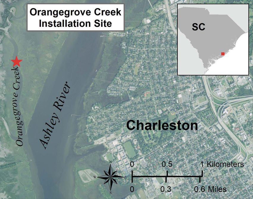
Acknowledgements

The South Carolina Department of Natural Resources’ (SCDNR) ACE Basin National Estuarine Research
Reserve (NERR) and Marine Resources Division, along with the North Inlet-Winyah Bay (NI-WB) NERR, col-
laborated with the South Carolina Department of Health and Environmental Control’s Office of Ocean and
Coastal Resource Management (SCDHEC OCRM) to undertake this research project.

This work was sponsored by the National Estuarine Research Reserve System Science Collaborative, which
supports collaborative research that addresses coastal management problems important to the reserves.
The Science Collaborative is funded by the National Oceanic and Atmospheric Administration and man-
aged by the University of Michigan Water Center (NAI4NOS4190145).

This research project took a monumental amount of time and effort. The lead project team was Peter King-
sley-Smith, Nancy Hadley, Michael Hodges, Andrew Tweel, Sharleen Johnson, Denise Sanger, and Blaik
Keppler from SCDNR; Erik Smith and John Baker Stevens from NI-WB NERR; and Blair Williams, Kendra El-
liott, Elizabeth Hartje, Jessica Boynton, and Matt Slagel from SCDHEC OCRM. The effort required for the in-
stallation of the shoreline stabilization and restoration techniques and the monitoring of their effectiveness
was significant. We greatly appreciate the efforts of Benjamin Stone, Gary Sundin, Zach Bjur, Trent Austin,
Abigail Del Giorno, Austin Sturkie, Grace Smythe, Tyler Edwards, Greg Sorg, Holly Hillman, Holly Kight, Ryan
Raiford, Asa Julien, and Jake Sherry. The data was managed by Sharleen Johnson and Gary Sundin.

Additionally, many stakeholders participated in workshops, providing thoughtful input, feedback, and
data. We also appreciate the graphic layout support from Coastal Reserves and Outreach at SCDNR and the
graphic design support from Fatimah Bolhassan, NERRS Science Collaborative.

Recommended Citation: SCDNR. 2019. Summary of Living Shoreline Research to Inform Regulatory Decision-
Making in South Carolina. Charleston, SC: South Carolina Marine Resources Division. Technical Report No. 110.
49 p.

                                                      1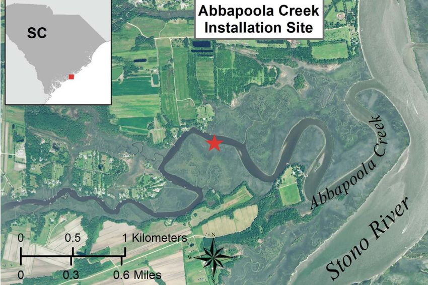
Table of Contents

Acknowledgements...............................................................................................................................................1

Table of Contents..........................................................................................................................................................2

Executive Summary.....................................................................................................................................................3

1.0 Introduction...........................................................................................................................................................4
      Co-benefits of Nature-based Solutions...........................................................................................................5
      Summary of Science Collaborative Project....................................................................................................6
      Purpose and Audience.......................................................................................................................................7

2.0 Regulations and Permitting Requirements.....................................................................................................8

3.0 Evaluated Living Shoreline Options.................................................................................................................9
      Oyster Shell Bags..............................................................................................................................................11
      Manufactured Wire Reefs (MWRs)...................................................................................................................15
      Coir Logs.............................................................................................................................................................20
      Salt Marsh Grass Planting................................................................................................................................26
      Oyster Castles....................................................................................................................................................30

4.0 Site Evaluation and Selection..........................................................................................................................31

5.0 Identification of Options for Greener Living Shorelines............................................................................36
       Setting Expectations.......................................................................................................................................39

6.0 References.............................................................................................................................................................43

7.0 Glossary.................................................................................................................................................................45

8.0 Appendix A. Interviews with Private Property Owners.............................................................................47

                                                                                      2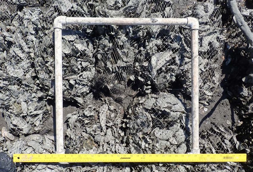
Executive Summary

Coastal marsh habitats are at risk due to sea level rise, increased storm intensity, coastline development,
and shoreline hardening. Living shorelines are a powerful tool to proactively protect estuarine shorelines.
Because of its extensive estuarine shoreline habitat, South Carolina is in an excellent position to take ad-
vantage of living shorelines to protect its salt marshes and improve coastal resiliency.

Living shorelines have been a part of the South Carolina Department of Natural Resources’ (SCDNR) coast-
al management, conservation, and education strategies for over 20 years. Constructing living shorelines
began as a habitat enhancement tool to increase the amount of oyster reefs and essential fish habitat. The
co-benefits of living shorelines, including shoreline stabilization and salt marsh expansion, quickly became
evident to SCDNR staff and to coastal property owners seeking to proactively protect the shoreline and
marsh habitat adjacent to their upland private property. Based on property owners’ increasing interest in
living shorelines and the benefits to the coastal environment, the South Carolina Department of Health
and Environmental Control’s Office of Ocean and Coastal Resource Management (SCDHEC OCRM) is pur-
suing a regulatory pathway to easily and effectively permit them. To ensure that the resulting regulations
and project standards developed are based on sound science, SCDNR, the North Inlet-Winyah Bay National
Estuarine Research Reserve (NI-WB NERR), and SCDHEC OCRM embarked on a joint multi-year project to
evaluate the effectiveness of a variety of greener living shoreline technologies under a number of coastal
environmental conditions.

This joint effort included monitoring older, pre-existing living shorelines, as well as installing and monitor-
ing new and previously used technologies under a range of environmental conditions. The technologies
tested at the new sites included bagged oyster shell, manufactured wire reefs (MWRs), and natural fibers.
The results and guidance contained herein are intended to provide SCDHEC OCRM with the science-based
information for creating a regulatory pathway and developing project standards for living shorelines in
South Carolina. This document will be updated as the science continues to develop, particularly with con-
tinued monitoring as living shorelines age.

Ultimately, the goal is for South Carolinians to have effective options to proactively protect marsh habitat
using living shorelines. This proactive approach will not only help to maintain or increase the salt marsh
footprint of the state, but it may also reduce the need for bulkheads or other hardened structures along
uplands, which can compromise coastal environments. This represents a step towards improving coastal
resiliency and sustainability in South Carolina.

                                                       3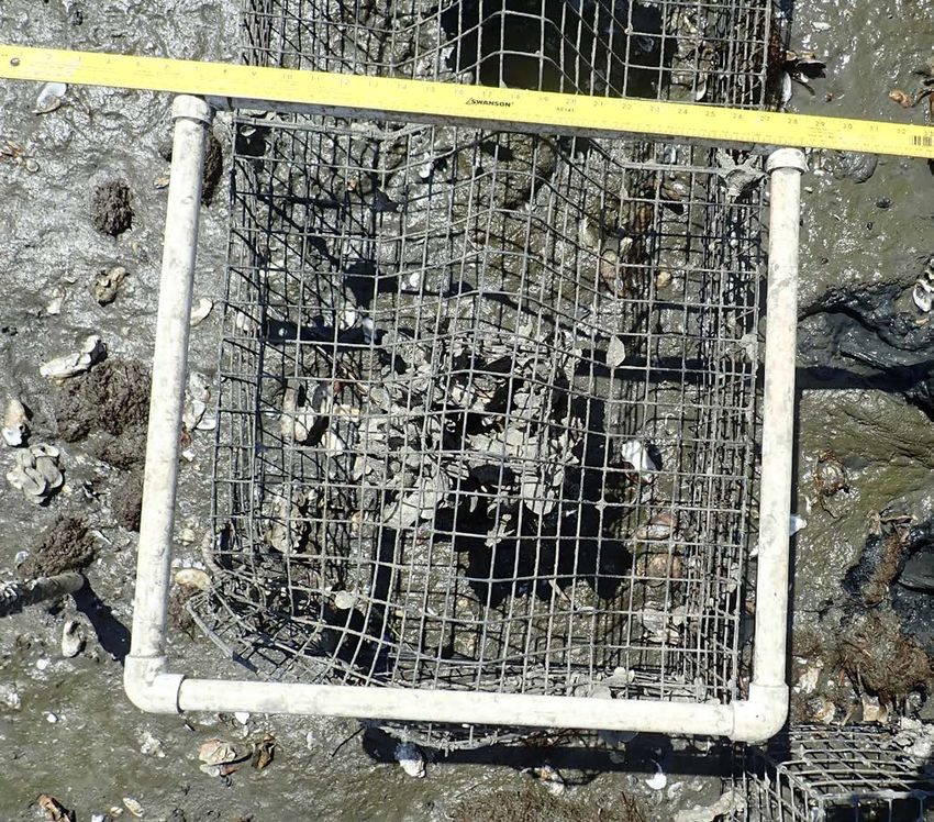
1.0 Introduction

Coastal estuarine marsh health and stability are a growing concern for South Carolinians as the coast-
al zone changes due to sea level rise and increasing development. There is, however, great potential for
nature-based solutions, such as living shorelines, to address these concerns. ‘Living shorelines’ is a broad
term that refers to diverse shoreline stabilization techniques ranging from marsh grass plantings to sills
and breakwaters, which are structural features placed parallel to the shoreline (Figure 1.1). In general, living
shorelines are intended to reduce wave energy and encourage sediment accretion behind them. In this
way, the marsh edge stabilizes and will often accrete to the point that it connects with the sill or breakwa-
ter.

Figure 1.1. NOAA’s “Coastal Shoreline Continuum and Typical Living Shorelines Treatments” (https://www.
fisheries.noaa.gov/insight/understanding-living-shorelines).

For the purposes of this document, ‘living shorelines’ refers to techniques intended to stabilize estuarine
shorelines at the marsh-water interface and facilitate the growth of marsh vegetation. These techniques
generally incorporate materials (e.g., oyster shells or coir logs) that serve as sills or sediment-trapping
devices and may or may not include marsh grass plantings. Because living shorelines have the potential to
be effective for shoreline stabilization as well as provide additional ecological benefits, state agencies and
others involved in coastal management and restoration encourage the use of living shorelines where they
are appropriate and would likely be effective.

Living shorelines are a particularly effective tool when used proactively to protect salt marshes (Figure
1.2). As defined in this document, they are placed at the marsh-water interface, buffering the marsh edge
against wave energy and increasing its resiliency and stability. There is tremendous environmental variabil-
ity across this interface. Substrate may range from soft mud to hard sand. Energy associated with currents
and waves varies from low-energy environments (e.g., inside bend of a waterway) to high-energy environ-
                                                       4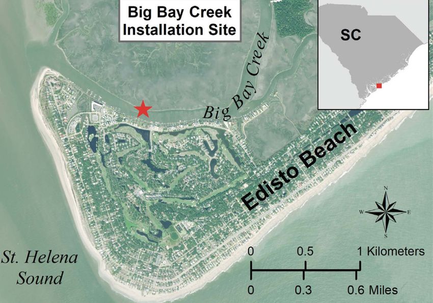
ments (e.g., Intracoastal Waterway). This project focused on the softer, greener side of the living shoreline
spectrum (Figure 1.1), which may not be appropriate or effective in all situations. For instance, the living
shoreline techniques tested in this study may not be appropriate in the face of an eroding upland, where
the salt marsh is nonexistent and the shoreline slope is high. However, other living shoreline techniques
may be appropriate for such circumstances. This project addressed the marsh-water interface and is not
intended to address the upland-water interface (Figure 1.2).

Figure 1.2. An example shoreline and area of concentration for this project (red arrow).

Living shoreline techniques are being used throughout the United States, with many agencies and nonprof-
it organizations developing data and information. The National Oceanic and Atmospheric Administration
(NOAA) developed guidance for using living shorelines in 2015 (NOAA, 2015). Since environmental condi-
tions and state regulations vary tremendously across the United States, a number of states, such as North
Carolina (North Carolina, 2006), Virginia (Hardaway et al., 2017), and New Jersey (Miller et al., 2016), have
developed guidance documents appropriate for their local conditions. The information from many of these
other documents aided in the development of the framework for this document.

Co-Benefits of Nature-Based Solutions

There are a number of ecosystem benefits from living shorelines. Living shorelines are a management tool
that not only provides shoreline protection benefits, but also creates habitat, promotes marsh growth,
withstands storms, may have the ability to keep pace with sea level rise, and may filter the water. These
benefits, provided by natural solutions, or free ecosystem services, enhance the health and resilience of
our coasts.

Living shorelines are great habitat creators. In South Carolina, living shoreline construction often utilizes
oysters to form a sill. The oyster reefs themselves provide important habitat for a multitude of species.
More than 83 species of finfish and invertebrates are associated with intertidal oyster reefs in South Caroli-
na, including all 22 managed by the Atlantic States Marine Fisheries Commission (ASMFC, 2007). Within the
southeastern U.S. region, the South Atlantic Fishery Management Council recognizes oyster reefs as essen-
                                                      5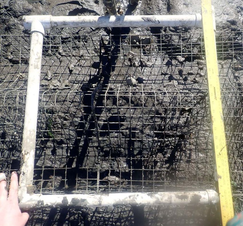
tial fish habitat, which as defined by Congress includes “those waters and substrate necessary to fish for
spawning, breeding, feeding or growth to maturity.” Furthermore, oyster reefs are well documented in their
ability to improve water quality and clarity through their removal and deposition of suspended particles
via filter feeding (e.g., Dame, 1999; Dame et al., 2001).

Living shorelines, whether oyster-based or not, promote the growth of the marsh. They create additional
marsh habitat as sediment and marsh vegetation fill in behind them. Salt marshes are one of the most bio-
logically productive and ecologically valuable habitats in the coastal region (Peterson et al., 2007). They are
highly effective at capturing and holding carbon from the atmosphere, acting as carbon ‘sinks,’ which help
to mitigate the effects of climate change caused by increasing carbon dioxide levels (NOAA, 2019). Marshes
also remove excess nutrients from the water and reduce flooding by slowing and absorbing water (Tiner,
1993).

In terms of storm protection, natural marshes and those with a constructed living shoreline offer better
protection to shorelines than bulkheads from significant storm events (Gittman et al., 2014). Many property
owners assume that bulkheads provide superior protection from erosion and storm damage (Fear & Cur-
rin, 2012; Scyphers et al., 2014); however, studies to support this, particularly under storm conditions, are
lacking (Shepard et al., 2011). Furthermore, studies show that bulkheads experience considerable damage
during extreme storm events, compared with more natural systems that exhibit both greater resilience and
recovery following such weather events (Currin et al., 2008; Gittman et al., 2014).

In addition to storm protection, living shorelines that are oyster-based may offer a buffer against the threat
of sea level rise. As sea level rises, oyster reef heights will naturally increase; therefore, the reefs persist as
natural, growing breakwaters which adjust to the change in tidal elevation (e.g., Rodriguez et al., 2014).

The co-benefits of living shorelines stand in contrast to the harder, grayer structures like revetments and
bulkheads. Harder structures convey none of the additional benefits that living shorelines provide and can
be detrimental to coastal environments. They isolate the estuary from the upland, disrupting the land-wa-
ter continuum and restricting sediment supply to the marsh (Redfield, 1972; Chauhan, 2009). They also
restrict the ability of coastal marshes to migrate upland or increase in height as sea levels change (Peterson
et al., 2008b; Titus, 1988). Hard structures reflect wave energy, which increases the potential for erosion
and sediment scour (National Research Council, 2007). Essentially, the presence of a bulkhead eliminates
the intertidal zone, transforming a formerly gently sloped shoreline into a steep vertical structure (see
Currin et al., 2010 and references within). As a result, bulkheads are associated with reduced abundances
of upland coastal marsh plants, benthic infauna, and fish and crustaceans (Bozek & Burdick, 2005; Seitz et
al., 2006; Bilkovic & Roggero, 2008).

Summary of Science Collaborative Project

Over the last 20 years, SCDNR, the US Fish and Wildlife Service (USFWS), and The Nature Conservancy
(TNC) have implemented a large number of oyster-based living shorelines. In particular, the SCDNR has
constructed oyster-reef based living shorelines adjacent to public lands since 2001. Through the South
Carolina Oyster Restoration and Enhancement (SCORE) Program (Hadley et al., 2010) and ongoing research
by the Shellfish Research Section of the SCDNR’s Marine Resources Research Institute (MRRI), more than
200 oyster-based living shoreline projects have been constructed, using several restoration methods known
to be successful in coastal South Carolina. These methods have included installing loose oyster shell,
bagged oyster shell, ‘oyster castles®’ produced by Allied Concrete Inc., cement-coated derelict and repur-
posed crab traps (RCT), and cement-coated manufactured wire reefs (MWRs).

                                                         6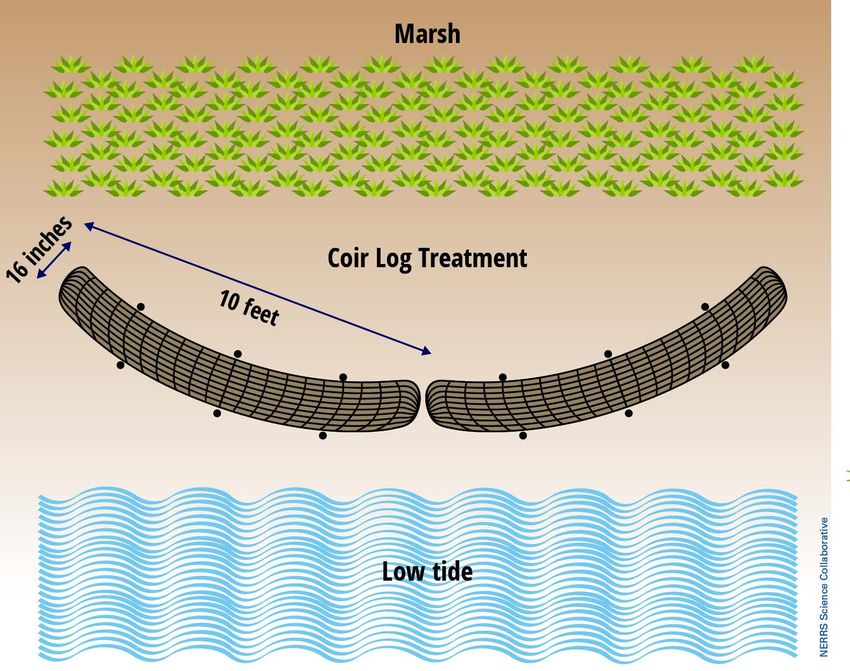
Many of these oyster-based living shorelines were constructed in highly visible locations to serve as
demonstration sites. Coastal property owners over the years witnessed the shoreline stabilizing effect at
these sites; many became interested in using living shorelines to address shoreline issues associated with
their own properties. However, SCDHEC OCRM does not currently have regulations specific to living shore-
lines, making permitting them a sometimes lengthy and challenging process (see Appendix A: 2017-2018
survey of private property owners interested in living shorelines).

SCDHEC OCRM recognized the need for new scientific information specific to the South Carolina environ-
mental conditions on which to base new regulations and a streamlined permitting process for living shore-
lines. While SCDNR had data on the effectiveness of oyster-based living shorelines for over 200 locations,
these data had not been comprehensively analyzed to establish relationships between site conditions and
living shoreline performance and effectiveness. The SCDNR study sites were constructed at sites carefully
selected to maximize their success at creating oyster habitat, including optimal salinities for oyster growth
and recruitment as well as ideal bank slope and substrate type. SCDHEC OCRM and SCDNR, along with NI-
WB NERR, worked together to define information needs and data gaps to develop a robust assessment of
living shorelines applicable to all of the South Carolina coastal zone.

To obtain the scientific information to effectively permit and provide guidance for construction of living
shorelines, SCDHEC OCRM, SCDNR, and NI-WB NERR partnered on a project funded by the NOAA Nation-
al Estuarine Research Reserve System (NERRS) Science Collaborative Program. The goal of this research
project was to generate the science-based information that SCDHEC OCRM needed to make effective policy
decisions regarding living shorelines. This project experimentally tested the performance of softer, greener
shoreline stabilization materials, including bagged oyster shell, MWRs, and natural fibers, under a broad
range of conditions found in the South Carolina coastal zone (Tweel et al., in prep). Existing oyster-based
living shoreline sites spanning a wider range of ages were monitored to provide an understanding of the
performance over time (Kingsley-Smith et al., in prep). Monitoring of the new installation sites had only
occurred for 1-2 years at the time this summary was developed.

Results of the joint project have improved the understanding and potential of living shorelines within the
South Carolina coastal zone. As the chief end user of the information, SCDHEC OCRM has identified the
development of a living shoreline regulatory definition and project standards as a priority for the com-
ing years and will be directing funding to this initiative using their Coastal Zone Management Act (CZMA)
Section 309 strategy. Through that funding, this document will be updated with the results from additional
monitoring of recently created living shorelines sites, scheduled for the spring of both 2019 and 2020.

Purpose and Audience

The purpose of this document is to provide SCDHEC OCRM with research findings and science-based guid-
ance as the basis for permitting living shorelines. The science-based guidance provided here is intended
for SCDHEC OCRM staff who are responsible for the evaluation and permitting of living shorelines and who
are involved in the development of policy and regulatory standards for living shorelines. The information
provided may inform the regulatory and permitting framework. Entities, including the general public,
seeking to implement a living shoreline may also find the information contained in this document useful;
however, it does not contain detailed design specifications or maintenance protocols.

                                                      7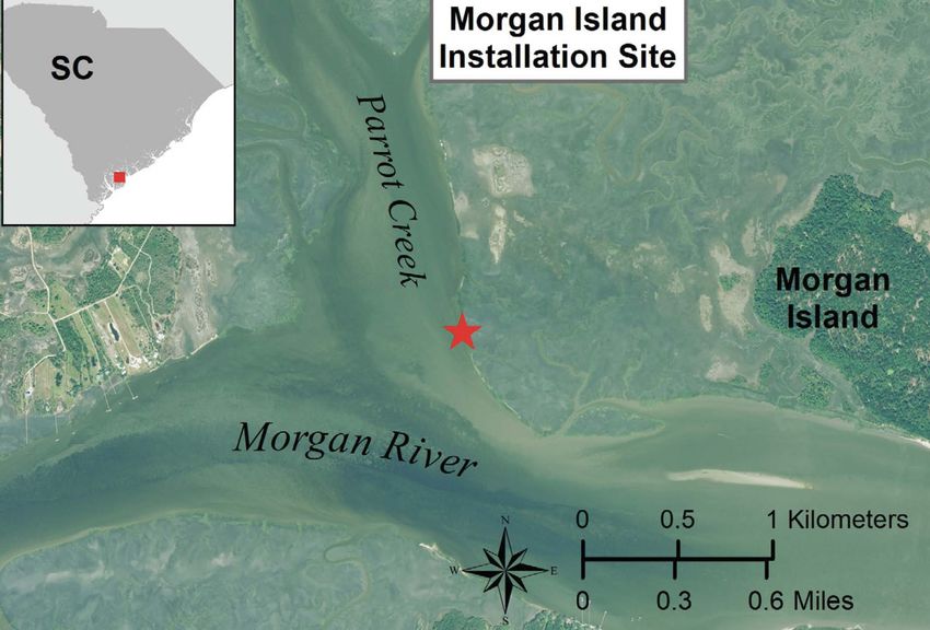
2.0 Regulations and Permitting Requirements

Contributed by SCDHEC OCRM

The South Carolina Coastal Tidelands and Wetlands Act (CTWA) was passed in 1977 by South Carolina’s
General Assembly. The CTWA created the South Carolina Coastal Council which would eventually become
the SCDHEC OCRM. Through the CTWA, SCDHEC OCRM is tasked with the protection and preservation of
coastal resources while promoting sound development practices within the coastal zone. The Coastal Divi-
sion Regulations (S.C. Code Ann. Regs. 30-1 et seq.), promulgated pursuant to the CTWA, provide standards
for evaluating activities that utilize the critical areas of the state. Over the years, these regulations have
been amended to provide additional guidance to the regulated public and to reflect the progression of
coastal management in the state. The increased interest in living shorelines highlights the need for specific
project standards and guidance for the permitting and construction of living shoreline projects. Currently,
the lack of specific project standards, or even a regulatory definition, for living shorelines results in longer
permit review times, loose design requirements, and potentially ineffective projects.

The current regulations for shoreline stabilization only address traditional erosion control structures
including bulkheads and rip-rap revetments. Per the existing regulations, erosion control structures are
prohibited at sites that have an adequate marsh buffer which serves to protect the upland shoreline from
tidally induced erosion (R. 30-12(C)(1)(c)). Where permissible, erosion control structures are required to
conform to the critical area line (upland boundary) with allowances for up to 18 inches of channel ward
extension when construction at the critical line is not feasible (R. 30-12(C)(1)(a)and(b)). All erosion control
structures, including living shorelines, are authorized through an individual Critical Area Permit. Due to the
complexities of living shorelines, these installations are subject to more rigorous review under the current
regulatory framework.

Using information gathered by SCDNR, SCDHEC OCRM will consider regulatory options to streamline and
simplify authorization of living shoreline installations. This may encourage property owners to use living
shorelines as an alternative to hardened erosion control structures, which has the potential benefit of cre-
ating marsh and reducing the negative impacts that can result from hardening estuarine shorelines.
SCDHEC OCRM coordinates closely with the U. S. Army Corps of Engineers on projects such as living shore-
lines which alter the critical areas. This study will inform state permitting decisions. Any individual property
owner wanting to install a living shoreline must coordinate with the U.S. Army Corps of Engineers to deter-
mine if federal authorization is required.

                                                       8
3.0 Evaluated Living Shoreline Options

Over the last two decades, multiple organizations (e.g., SCDNR, USFWS, and TNC) have implemented oys-
ter-based living shorelines in South Carolina. The purpose of most of these living shoreline installations
was the creation of oyster habitat. Shoreline stabilization emerged as a secondary benefit. Therefore, a
subset of these previously constructed living shorelines was assessed to better understand their long-term
performance in the context of shoreline stabilization (Figure 3.1).

Figure 3.1. Map of existing South Carolina reef locations from 2001-2016 (blue and red symbols). A subset
of reefs from this project were selectively monitored for this project (red symbols), representing a range of
reef ages (0 to 16 years).

In addition, an experimental approach was utilized to better understand the relative performance of var-
ious oyster- and non-oyster-based living shoreline materials when installed at sites representing typical
shoreline conditions occurring in coastal South Carolina. Experimental living shorelines were installed at
a total of 16 locations (Figure 3.2). The techniques tested included oyster shell bags, manufactured wire
reefs (MWRs), coir logs, and Curlex® Blocs. These do not represent the full spectrum of living shoreline

                                                      9
materials but were considered suitable green approaches for application in South Carolina. Control areas immediately adjacent and equivalent in size to the living shoreline treatments were also established and monitored as part of the experimental approach at each site. Curlex® Blocs (American Excelsior Company), made of aspen fiber wrapped in a biodegradable sock, were included as a previously untested material in the marine environment. Curlex® Blocs, as purchased, degraded too quickly (
In South Carolina, we find ourselves in the fortunate position of being able to utilize oyster-based tech-
niques for many of our living shorelines. This is because in South Carolina, oysters are primarily intertidal;
therefore, when they form reefs, those reefs serve as natural breakwaters, sheltering the shoreline from
wave energy and promoting growth of the marsh. Additionally, between April and September, South Car-
olina waters are teeming with oyster larvae seeking an appropriate place to settle. Oyster recruitment is
substrate-limited, so when an appropriate substrate is added in an area with oyster-supporting salinity
conditions, it will likely recruit young oysters. The potential for non-oyster-based techniques was also of
interest. The information provided below summarizes the conditions and success of the three materials
utilized in this study.

Oyster Shell Bags

Oyster shell bag reefs have been used as a basis for living shoreline projects to increase habitat diversity
and provide shoreline protection in South Carolina since the early 2000s. This method is most successful
at locations conducive to oyster recruitment and growth. Oyster shell bag reefs consist of nontoxic, UV-sta-
bilized mesh bags filled with substrate (primarily oyster shell) that facilitates the recruitment and develop-
ment of oyster larvae. These bags are placed in the intertidal zone at the midpoint between the eroding
bank and the mean low water (MLW) line. Placing the shell into bags creates a stable reef structure that
buffers incoming wave energy and facilitates accumulation of fine sediment on the shoreward side of the
reef. Design modifications can be made to oyster shell bag reefs to increase their chance of success at sites
with challenging environmental conditions. Shell bags do not perform well at sites where the sink depth is
more than 4 in (10 cm) into the sediment or in portions of a creek system with large amounts of sediment
deposition. At these sites, shell bags sink into or become covered in sediment, resulting in oyster recruit-
ment failure. Problems with soft sediment or high sedimentation conditions can be mitigated by installing
a footprint of wood pallets on the intertidal bank beneath the shell bags. This helps to distribute the weight
and increases the elevation of the reef, thereby preventing the reef from sinking into the sediment. The
resulting higher profile helps to maintain the shell bags above the soft sediment so that oyster recruitment
and growth can occur. Shorelines with steep intertidal banks (>16% slope), especially at sites where the
sediment is soft (>10 cm sink depth) and fine (>70% silt/clay and
Figure 3.3. Overhead (left) and cross section (right) of a typical bagged oyster shell reef design with shell
bags placed atop wood pallets.

Site Examples

Big Bay Creek, Edisto Island

The shell bag experimental treatment on Big Bay Creek (32.49352, -80.33596) was installed in July 2016
along an intertidal bank located on the inside bend of this creek (Figure 3.4). The waterbody width is 344
ft (105 m). This site is considered low energy due to the small waterbody width, the sheltered environment
provided by an inside bend, and its placement within a No Wake Zone. The intertidal bank where the shell
bags were placed had a slope of 26%, which is above the recommended 16% for a viable range for this
type of treatment. Immediately prior to installation, the surface sediment was 65% sand and 35% silt/clay.
The bank width was 15.7 ft (4.8 m) and the escarpment (i.e., the erosional area of shoreline that has some
degree of vertical relief) height averaged 1.8 ft (55 cm). The 4-in (10-cm) sink depth (i.e., the depth to which
a cinderblock sinks into the substrate) resulted in a sediment firmness classification of soft; thus, it was
decided to place the shell bags on wooden pallets.

During the first two years following installation, a total of 10 in (26 cm) of fine sediment accumulated on
the bank immediately upslope of the reef, and 9.4 in (24 cm) of sediment accumulated on the bank 30 cm
(1 ft) upslope of the reef. During this same time period, the sediment surface elevation at a nearby control
area decreased by 2.7 in (7 cm). Most of the sediment accumulation occurred during the first year after
installation. In addition to sediment accumulating in the newly sheltered area behind the reef, sediment
also collected on top of many of the shell bags located on the upslope portion of the reef, decreasing the
available area for oyster recruitment and development (Figure 3.4). Percent oyster cover, measured at the
mid-slope position of the reef, decreased from 26% one year after installation to 2% two years after instal-
lation. Oysters in the lower, non-sediment-covered portions of this reef are, however, growing well (Figure
3.4). Even though the slope is steep and the baseline sink depth was moderately high, the rebar has been
successful at holding the treatment in position on the bank; this could be due to the fact that the sediment
was 65% sand with relatively large sand grains (the other 35% was silt/clay). After two years, marsh expan-

                                                       12
sion was occurring at this location (Figure 3.4), likely facilitated by the sediment stabilized by and accumu-
lating behind the shell bag reef.
Figure 3.4. Aerial view of the living shoreline research site on Big Bay Creek (upper left). Shell bag reef
constructed on wooden pallets in July 2016 (upper right). Oyster growth and sediment accumulation on
reef at Big Bay Creek in November 2017 (one year post-install; lower left) and in September 2018 (two years
post-install; lower right). Note marsh grass expansion (lower right).
Abbapoola Creek, Charleston
The shell bag experimental treatment on Abbapoola Creek (32.66956, -80.02127) was installed in June 2016
along an intertidal bank located on a straight section of the creek (Figure 3.5). The waterbody width at this
location measured 253 ft (77 m), and this site is considered low energy due to its narrow water width and
relatively low boat traffic. At baseline, the intertidal bank where the shell bags were placed had a slope of
16%, and 70% of the surface sediment was made up of silt/clay (the other 30% was sand). The bank width
was 13.4 ft (4.1 m), and the escarpment height averaged 1.4 ft (43 cm). The baseline sink depth at this treat-
ment (4.9 in; 12.5 cm) resulted in a sediment firmness classification of soft; therefore, the shell bags were
placed on wooden pallets (Figure 3.5).
During the first two years following installation, a total of 11.5 in (29 cm) of silt/clay sediment accumulated
on the bank immediately upslope of the reef. A greater amount of sediment accumulated during the first
year (9 in; 23 cm) than during the second year (2.5 in; 6 cm). On the bank 1 ft (30 cm) upslope of the reef,
10.1 in (26 cm) of sediment accumulated, and during this same 2-year time period, the sediment surface
elevation at a nearby control area decreased by 1.9 in (5 cm). Moderate sediment accumulation on top of
the reef decreased the available area for oyster recruitment and development (Figure 3.5). Percent oyster
13cover, measured at the mid-slope position of the reef, was 41% one year post-installation and 35% two
years post-installation. After two years, oysters were growing well on all non-sediment-covered portions of
this treatment. One side of this treatment slid a moderate distance down the bank, likely because the slope
was fairly steep and the sediment was muddy (70% silt/clay). A slight amount of marsh expansion has been
observed behind the oyster sill at this location (Figure 3.5).
Figure 3.5. Aerial view of the living shoreline
research site on Abbapoola Creek (upper left).
Shell bag constructed on wooden pallets in June
2016 (upper right). The same reef in August 2018
(2 years post-install; lower left). The close side of
the reef has slid a short distance down the bank,
away from the monitoring PVC pole.
Morgan Island, St. Helena
The shell bag experimental treatment on Morgan Island (32.46485, -80.54217) was installed in July 2016
along an intertidal bank located on an outside bend shoreline along Parrot Creek, where it joins with the
Morgan River (Figure 3.6). The waterbody width at this location measured 2,749 ft (838 m). This site is con-
sidered high energy because it is exposed to relatively high wind, wave, and tidal flow energy associated
with its waterbody width and proximity to the Morgan River. At baseline, the intertidal bank where the shell
bags were placed had a slope of 4%, and 92% of the surface sediment was made up of silt/clay (the other
8% was sand). The bank width was 85.3 ft (26.0 m), and the escarpment height averaged 2.1 ft (64 cm). The
8.2-in (20.9 cm) sink depth resulted in a sediment firmness classification of very soft; thus, it was decided
to place the shell bags on wooden pallets (Figure 3.6).
During the first two years following installation, a total of 5.4 in (14 cm) of fine sediment accumulated on
the bank immediately upslope of the reef. A greater amount of sediment accumulated during the first year
(4.2 in; 11 cm) than during the second year (1.3 in; 3 cm). On the bank 1 ft (30 cm) upslope of the reef, 1.4 in
(4 cm) of sediment accumulated, and during this same 2-year time period, the sediment surface elevation
at a nearby control area decreased by 4.1 in (11 cm). Percent oyster cover, measured at the mid-slope posi-
tion of the reef, was 4.3% one year post-installation and 4.5% two years post-installation (Figure 3.6). Low
recruitment of oysters appears to be cause for the low percentage of oyster coverage, but not due to lack of
14substrate; the shell bags have not been covered by sediment. Although the sediment was muddy (92% silt/
clay and 8% sand), this technique remained in place (i.e., it did not slide down the bank), likely because the
slope was so gentle (4%). Marsh expansion has not yet been observed at this location.
Figure 3.6. Aerial view of the living shoreline research site on Morgan Island (upper left). Shell bag con-
structed on wooden pallets in July 2016 (upper right). Percent oyster coverage (lower left) and shell bag
reef (lower right) in August 2018.
Manufactured Wire Reefs (MWRs)
Repurposed crab traps coated in cement have been used in living shoreline projects to increase habitat di-
versity and provide shoreline protection in South Carolina since 2011. SCDNR has been successful in using
cement-coated repurposed abandoned and donated crab traps that rapidly attract larval oysters, yielding
high coverage supported by rapid growth. Private citizens, however, do not have access to large numbers of
used crab traps. The State of South Carolina discourages anyone from removing crab traps from estuaries
in case they are not actually abandoned. It is unlawful to “remove, willingly damage, or interfere with any
fishing equipment belonging to another” [Section 50-5-105 (A)]. Crab traps that are suspected to be aban-
doned can be reported to crabtraps@dnr.sc.gov. More information on this topic is available at http://www.
dnr.sc.gov/marine/crabtraps/.
Due to the success of the repurposed crab trap method – but limited availability for private citizen use –
SCDNR began testing MWRs (Figure 3.7). MWRs can be manufactured for the purpose of creating an oys-
ter-based living shoreline adjacent to private property. MWRs are constructed from the same wire mesh
15and have the general shape typically used for the construction of recreational and commercial crab traps.
Raw materials and tools can be purchased online. At this time, these structures are not currently available
for purchase “off the shelf” from any retailer, but customized orders can be made through crab trap sup-
pliers. The galvanized wire mesh can either be uncoated or coated with vinyl. The mesh is coated in a thin
layer of cement to serve as an attractive substrate for the settlement of larval oysters. A thinset tile mortar
is typically used, since it adheres relatively well to the wire mesh and is cost effective. The mortar is mixed
with water in a cement mixer to the proper consistency and then placed in a cement sprayer. A thin layer
is applied to the entire surface of each MWR unit and then left to cure for at least two weeks prior to use in
the construction of a living shoreline.
Figure 3.7. Manufactured wire reefs (MWRs) were devel-
oped as an option similar to repurposed crab traps.
MWRs are 4 ft (1.2 m) long, 2 ft (0.61 m) wide, and 18 in (45.7 cm) high. They are manufactured with these
dimensions to create more surface area for larval oyster recruitment compared with crab traps (2 ft x 2 ft
x 2 ft; 0.61 m x 0.61 m x 0.61 m). MWRs are installed on the intertidal bank halfway between the waterward
marsh edge and the mean low water line to provide optimal conditions for oyster survival and productivity
(Figure 3.8). SCDNR tested MWRs in a staggered checkerboard-like pattern to maximize surface area while
creating one contiguous structure. They are secured to the sediment using #3 J-bar rebar that is at least 24
inches long and has a 4-inch candy cane bend, which is placed into the sediment through the mesh of the
reef at four points (two on each side), holding the reef in place on the bank. These structures are well-suit-
ed for sites where the sediment is too soft for traditional reef materials such as bagged oyster shell. MWR
units are also much lighter than bagged shell, take less effort to install, and, due to the finite supply of oys-
ter shell, are likely to be a more viable option for installing oyster-based living shorelines at a commercial
scale.
It appears that the vinyl-coated mesh may remain intact longer than the exposed wire; however, additional
side-by-side assessment of the two versions of MWR units is required to evaluate this issue.
Recruitment of oysters on MWRs is not immediate. It may take 2-3 years before the MWR is well colonized
by juvenile oysters. Juvenile oysters grow rapidly, but it takes up to 1-2 years for them to reach a size that
effectively traps sediment. MWRs will take longer than bagged shell to achieve a similar percentage of
oyster cover. Therefore, it will take longer for the MWRs to provide shoreline protection that is similar to
traditional bagged-shell-based approaches. Once established, however, the top surface of MWRs will have
a higher elevation than bagged shell or bagged-shell-on-wood-pallets methods, which will likely make
MWRs less susceptible to being covered by sediment in high-sedimentation environments. Also, due to
their higher profile, MWRs will have the capacity to trap a greater volume of sediment along the upslope
portion of the bank after becoming fully colonized by oysters. A better understanding of the variation in
recruitment and growth of oysters on the different types of MWRs could be achieved by future side by side
comparisons.
16Figure 3.8. Overhead (left) and cross section (right) views of a typical manufactured wire reef (MWR) design
in the intertidal zone used for this study.
Site Examples
Big Bay Creek, Edisto Island
The vinyl-coated MWR experimental treatment on Big Bay Creek (32.49354, -80.33606) was installed in July
2016 along an intertidal bank located on the inside bend of this creek (Figure 3.4). The waterbody width at
this location measured 344 ft (105 m), and this site was considered low energy due to the small waterbody
width, the sheltered environment provided by an inside bend, and its location within a No Wake Zone.
At baseline, the intertidal bank where the MWRs were placed had a slope of 28%, and 35% of the surface
sediment was made up of silt/clay (the other 65% was sand). The bank width was 15.7 ft (4.8 m) and the
escarpment height averaged 2.3 ft (70 cm). The 4.1-in (10.3 cm) sink depth resulted in a sediment firmness
classification of soft.
During the first two years following installation, a total of 3.7 in (9 cm) of fine sediment accumulated on
the bank immediately upslope of the reef, and 4.8 in (12 cm) of sediment accumulated on the bank 1 ft (30
cm) upslope of the reef. During this same time period, the sediment surface elevation at a nearby control
area decreased by 2.7 in (7 cm). This treatment has successfully maintained its location on the bank, with
no sliding downslope. Oyster recruitment and growth, on the surface of the wire, increased markedly from
11% at one year post-installation (less than at the shell bag reef at this site) to 54% at two years post-in-
stallation (greater than at the shell bag reef at this site; Figure 3.9). As seen in a photo taken in May 2019, 34
months after installation, marsh expansion has started to occur at this location (Figure 3.10).
17Figure 3.9. Live oyster coverage on MWRs at Big Bay Creek in October 2017 (one year post-install; left) and
September 2018 (two years post-install; right).
Figure 3.10. Almost 3 years after installation of the
MWR at Big Bay Creek, oyster cover and growth
continue to increase, and marsh expansion was
starting to occur. Photo taken in May 2019.
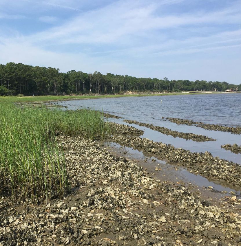
18Orangegrove Creek, Charleston
The vinyl-coated MWRs experimental treatment on Orangegrove Creek (32.80887, 79.97745) was installed
in August 2017 along an intertidal bank located on the inside bend of this creek (Figure 3.11). The water-
body width at this location is 203 ft (62 m), and this site is considered low energy due to limited boat traffic,
the sheltered environment offered by the inside bend position, and the narrowness of the creek. This was
the narrowest waterbody width of any site monitored for this project. At baseline, the intertidal bank along
this shoreline had a slope of 20%, very muddy sediment (97% silt/clay and 3% sand), and a sink depth (7.4
in; 21.3 cm) that resulted in a sediment firmness classification of very soft. The bank width was 10.8 ft (3.3
m), and the escarpment height averaged 1.5 ft (44.4 cm).
During the first 20 months post-installation, a total of 5.3 in (13 cm) of fine sediment accumulated on the
bank 1 ft (30 cm) upslope of the reef. During this same time period, an average of 7.5 in (19 cm) of sedi-
ment elevation was lost at a nearby control area. Oyster recruitment and growth on the surface of the wire
remains fairly limited at 20 months post-installation (Figure 3.11), but this treatment has only been in the
environment for one full oyster recruitment season thus far. This treatment slid slightly down the bank,
likely due to the relatively steep slope and very muddy sediment.
Figure 3.11. Living shoreline research site on Orangegrove Creek with an aerial view (left). Live oyster
coverage on MWR at Orangegrove Creek in April 2019 (right) with limited recruitment and growth after 21
months.
Morgan Island, St. Helena
The vinyl-coated MWR experimental treatment on Morgan Island (32.46501, -80.54226) was installed in July
2016 along an intertidal bank located on an outside bend shoreline on Parrot Creek, where it joins with the
Morgan River (Figure 3.12). The waterbody width at this location measured 2,749 ft (838 m). This site was
considered high energy because it is exposed to relatively high wind, wave, and tidal flow energy associat-
ed with its waterbody width and proximity to the Morgan River. At baseline, the intertidal bank where the
shell bags were placed had a slope of 10%, and 95% of the surface sediment was made up of silt/clay. The
bank width was 85.3 ft (26.0 m), and the escarpment height averaged 2.3 ft (70 cm). The 8.2-in (20.9 cm)
sink depth resulted in a sediment firmness classification of very soft.
19On the bank 1 ft (30 cm) upslope of the reef, there was a net loss in sediment surface elevation of 4.0 in (10
cm) during the first two years after installation. During this same 2-year time period, the sediment surface
elevation at a nearby control area decreased by 4.1 in (11 cm). Wind and wave energy from Hurricane Mat-
thew, in October 2016, caused multiple MWR units to become dislodged (Figure 3.12). These MWR units and
associated rebar were found less than 305 ft (100 m) away at the next site visit and were easily re-anchored
to the remaining original reef structure. Percent oyster cover was 0.9% one year post-installation and 14.8%
two years post-installation (Figure 3.12). Marsh expansion has not yet been observed at this location.
Figure 3.12. Aerial view of the living shoreline research site on Morgan Island Creek (upper left). Two MWR
units were dislodged and relocated nearby by Hurricane Matthew (lower left) but were easily moved back
into position. Live oyster coverage on MWR in August 2018 (upper and lower right).
Coir Logs
There are scenarios where oyster-based methods are not appropriate or potentially less effective than
other alternatives. For example, if the salinity is too low or too variable to support oyster populations, or if
someone wants to stabilize a shoreline for a short time period, then an alternative may be more suitable.
Coir logs have been used in living shoreline applications in several states as an alternative to oyster-based
shoreline stabilization and protection methods. These logs are used to combat erosion caused by wave
energy and to trap sediment on the shoreward side of the log. As the coir log stabilizes and accretes sed-
iment, marsh plants can colonize the portion of the bank on the shoreward side of the reef. Coir logs are
20a living shoreline option suited for lower salinity or freshwater environments and potential areas that are
suitable for oyster growth but where oyster development is not of interest. The logs perform best in low
energy environments, as they tend to dislodge or degrade too quickly at sites with frequent boat wakes or
longer fetches. Coir logs will degrade over time and will need to be replaced on a periodic basis if the stabi-
lization of the marsh has not been achieved.
Coir logs are biodegradable cylinders of compressed coconut husk fiber, also known as coir (Figure 3.13).
They are available in a variety of lengths and widths but are typically sold in 10 ft (3.0 m) lengths. Coir logs
are wrapped in a coir or jute netting that contains the compressed coir. SCDNR has found it useful to wrap
the coir log in an additional layer of coir netting with smaller openings to better contain the compressed
coir fibers and lengthen the life span of the coir logs in the estuarine environment (Figure 3.13). A folded
underlayment of coir fabric is also beneficial at sites with soft or very soft sediment. This underlayment
reduces the amount that the coir log sinks into the soft sediment.
Figure 3.13. Coir log (10 ft length x 16 in diameter; 3 m x 41 cm)
with a single-layer tube of coir netting with smaller openings and
additional netting placed under the coir log to reduce sinking of
the log into the sediment.
Coir logs can be placed in a range of positions along the intertidal bank, extending from directly abutting
the marsh edge to halfway between the marsh edge and the MLW line. Coir logs should be deployed in a
gentle “U” configuration, with the inside bend of the U facing shoreward (Figures 3.14 and 3.15). Coir logs
can be placed in single or double rows. When installing a double-row coir log treatment, the shoreward
row may be placed at the marsh edge or pressed against an escarpment to shelter an eroding area from
wave energy, with the waterward row running parallel, approximately 6.6 ft or 2 m downslope, in order to
trap sediment between the rows of logs (Figures 3.14 and 3.15).
Regardless of their installation location, it is imperative that coir logs are securely staked and tied in place.
This can be done using rot-resistant wooden stakes with a hole drilled a few inches from the top through
which to pass coir twine. Stakes are pounded into the sediment through the folded coir mat resting under
the log at 1-ft (0.3 m) intervals around the perimeter. Coir twine is laced through the stakes with care to
ensure the stakes and coir twine are touching the log. Stakes are then pounded further into the sediment
until the coir twine is pressed tightly into the top surface of the log in order to reduce potential vertical
movement of the log (Figures 3.14 and 3.15). Additional stakes should be installed inward, in an A-frame
configuration, where the stakes are touching the coir log near the top surface and coming in contact with
each other in the air space over the top center surface of the coir log. A-frame stakes do not need eye holes
for twine; the stakes themselves will hold the log against the bank. The combination of vertical and A-frame
staking will prevent the log from sliding downslope (vertical stakes) and prevent vertical movement of the
log in response to wave energy (A-frame stakes), which can lead to the twine wearing and breaking (Figures
3.14 and 3.15). Coir logs that are not properly secured to the bank can go missing within one tidal cycle
regardless of the site conditions.
21Figure 3.14. Overhead (left) and cross section (right) of a typical single row coir log design in the intertidal
zone used for this study.
Figure 3.15. Coir rope laced through stakes
and tied to secure log in place (upper left).
Bagged oyster shell was used in front of some
coir logs to prevent undercutting of the log but
was later discontinued (upper right). Dou-
ble-row coir log at Orangegrove Creek, with
alternate A-frame staking, installed in August
2017 (lower left).
Coir logs are widely available and can be ordered through large home improvement stores or through
numerous online companies. A subject of particular concern is the mesh that contains the coir. Some
suppliers use a jute or coir netting that contains a monofilament line at its center. When the log inevitably
degrades, the monofilament line remains, which can be severely damaging to many marine species. There-
fore, the core of the mesh must consist of cotton twine and not monofilament line.
22Site Examples
Big Bay Creek, Edisto Island
The coir log experimental treatment on Big Bay Creek (32.49347, -80.33576) was installed in July 2016 along
an intertidal bank located on the inside bend of this creek (Figure 3.16). The waterbody width at this loca-
tion measured 344 ft (105 m), and this site was considered low energy due the small waterbody width, the
sheltered environment provided by an inside bend, and its location within a No Wake Zone. At baseline,
the intertidal bank where the coir logs were placed had a slope of 20%, and 36% of the surface sediment
was made up of silt/clay (the other 64% was sand). The bank width was 15.7 ft (4.8 m), and the escarpment
height averaged 2.1 ft (65 cm). The 4.1-in (10.3 cm) sink depth resulted in a sediment firmness classification
of soft.
During the first two years following installation, a total of 10.8 in (27 cm) of fine sediment accumulated on
the bank immediately upslope of the reef, and 10.9 in (28 cm) of sediment accumulated on the bank 1 ft (30
cm) upslope of the reef. During this same time period, the sediment surface elevation at a nearby control
area decreased by 2.7 in (7 cm). Most of the sediment accumulation occurred during the first year after
installation (Figure 3.16). Even though the slope was steep and the baseline sink depth was high, the stakes
and coir twine were successful at holding the treatment in position on the bank; this could be due to the
relatively coarse sediment (65% sand) present on the intertidal bank at baseline. Approximately 3 years
after installation (May 2019), natural (not planted) marsh grass has begun to colonize the bank behind the
coir log (Figure 3.16, lower right).
Figure 3.16. A single-row coir log treatment at Big Bay Creek (Figure 3.4) in July 2016 (upper left), October
2017 (upper right), September 2018 (lower left), and May 2019 (lower right).
23Orangegrove Creek, Charleston
The double-row coir log experimental treatment on Orangegrove Creek (32.80904, 79.97747) was installed
in August 2017 along an intertidal bank located on the inside bend of this creek (Figure 3.17). The water-
body width at this location measured 203 ft (62 m), and this site was considered low energy due to limited
boat traffic, the sheltered environment provided by an inside bend, and narrow creek width. This was the
narrowest waterbody width of any site monitored for this project. At baseline, the intertidal bank where
the coir logs were placed had a slope of 24%, and 95% of the surface sediment was made up of silt/clay.
The bank width was 10.8 ft (3.3 m), and the escarpment height averaged 1.2 ft (37 cm). The 8.4-in (21.3 cm)
sink depth resulted in a sediment firmness classification of very soft. The coir log closest to the marsh was
staked against the marsh grass and followed the contours of the escarpment, while the midpoint of the
shoreward coir log was staked 5.5 ft (1.7 m) from the upper coir log (Figure 3.17).
During the first 20 months post-installation, a total of 6.2 in (16 cm) of fine sediment accumulated on the
bank 1 ft (30 cm) upslope of the bottom row of coir logs (Figure 3.17). During this same time period, an av-
erage of 7.5 in (19 cm) of sediment elevation was lost at a nearby negative control area. One of the coir logs
in the escarpment edge row, at some point between monitoring in August 2018 and April 2019, broke away
from its stakes and went missing (Figure 3.17). While a significant amount of sediment had accumulated at
this treatment site, no marsh expansion has been observed to date.
Figure 3.17. Double-row coir log treatment at Orangegrove Creek in August 2017 (upper left), May 2018
(upper right), and April 2019 (lower). The upper left coir log went missing at some point between August
2018 and April 2019.
24Coosaw Cut, Bennetts Point
The single-row coir log experimental treatment at Coosaw Cut (32.52894, -80.44922) was installed in June
2016 and re-installed in September 2017 along an intertidal bank located on the dredged, straight section
of the Intracoastal Waterway (ICW) (Figure 3.18). The waterbody width at this location measured 427 ft (130
m), and this site was considered high energy due to the level of boat traffic on the ICW. At baseline, the
intertidal bank where the coir log was placed had a slope of 17%, and only 16% of the surface sediment
was made up of silt/clay (the other 74% was sand). The bank width was 24.1 ft (7.3 m), and the escarpment
height averaged 0.7 ft (22 cm). The 1.5-in (3.9 cm) sink depth resulted in a sediment firmness classification
of very firm. The waterward edge of the log was enforced with a single row of oyster shell bags, secured
along the coir log with rebar, to prevent undercutting of the coir log by tidal currents and boat wakes
(Figure 3.18).
Both coir log treatments, the 2016 installation and the 2017 installation, became dislodged before any
scheduled post-installation monitoring occurred. Both installations were documented as failures. The
single row of oyster shell bags installed adjacent to the coir log is still in place, and the oysters growing on
these shell bags are continuing to provide minimal protection to this area (Figure 3.18). All coir log treat-
ments installed at ICW sites for this project were considered failures. The use of coir logs at high-energy
sites, including locations along the ICW or sites exposed to high wind and wave energy as a result of large
water body widths, is not recommended.
Figure 3.18. Aerial view of the Coosaw
Cut experimental living shorelines site
(upper left). Coir log treatment imme-
diately after re-installation in Septem-
ber 2017 (upper right). At select sites,
bagged oyster shell was used in front
of the coir logs to prevent undercut-
ting of the log (upper right). Missing
coir logs with remaining oyster shell
bags in September 2018 (lower left).
25Salt Marsh Grass Planting
In addition to the erosion controls mentioned above, there are supplemental practices that can aid and en-
hance shoreline stabilization, primarily the planting of a marsh grass (e.g., Spartina alterniflora or smooth
cordgrass). All of the above methods are intended to promote sediment accretion with the ultimate goal
of marsh plant colonization. The root and rhizome network established by the growth and propagation of
marsh plants serves as a long-term sediment stabilization network.
With successful shoreline stabilization, establishment of the root and rhizome network often happens
naturally. In places where existing marsh plants are sparse, however, or in cases where an expeditious
timeline is preferred, planting of marsh grass is an option. It is important to choose an appropriate species
for planting. To determine the appropriate species of grass, the adjacent marsh grass should be identified.
In most estuarine areas, smooth cordgrass will be the dominant marsh grass species; however, in lower sa-
linity areas, another species may be more appropriate. Tools to assist with identifying native plant species
include field guides, smartphone apps such as iNaturalist, and websites. In addition, A Guide to the Salt
Marshes and Tidal Creeks of the Southeastern United States (www.saltmarshguide.org) provides informa-
tion about common plants found along estuarine shorelines in South Carolina.
Smooth cordgrass and other native marsh plants can be acquired by contacting local plant nurseries that
grow native wetland plants. SCDNR has only planted smooth cordgrass. The following best practices are for
this species, but it is likely that the recommendations are relevant to other marsh grasses.
Mature plants can be successfully planted behind the living shorelines used in this project without re-
quiring any further growth or care prior to installation. The hardiness of each plant will vary, but mature
plants should have a developed root or rhizome network prior to planting. Proper planting is crucial to a
successful installation. It is recommended that the living shoreline be left unplanted for at least one year
post-installation, so that the sediment behind it has a chance to accumulate and stabilize. The elevation of
the sediment should be high enough to be dry and completely exposed at low tide for smooth cordgrass to
be successful. Smooth cordgrass will not survive at sites that are fully submerged. Findings from this study
indicate smooth cordgrass should not be planted below 3.3 ft (1 m) mean high water (MHW).
The hole dug for each plant must be deep enough so that after planting, the roots are completely covered
by the displaced sediment to a depth of at least one inch. The goal is to secure each plant to prevent the
plug from floating away with the next tide. Success of the planting is measured in two phases; the first is
that plants remain in place throughout the next few tidal cycles. The second is the regrowth of vegetation
the following spring. Planted smooth cordgrass often lose a large portion of their leaf area to wave damage
after installation, but if the rhizome network is intact, the leaves should rebound the following year.
Site Examples
Big Bay Creek, Edisto Island
Two single-row coir log treatments were installed in July 2016 along an intertidal bank located on the in-
side bend of Big Bay Creek (Figure 3.16). The waterbody width at this location measured 344 ft (105 m), and
this site was considered low energy due to the small waterbody width, the sheltered environment provided
by an inside bend, and its location within a No Wake Zone. At the time of installation, the slopes for the two
treatments were 19% and 20%, and the sediment was relatively sandy (63% sand and 37% silt/clay). The
bank width was 15.7 ft (4.8 m) and the escarpment heights for the two treatments averaged 2.4 ft (74 cm)
and 2.1 ft (65 cm). The 4.1 in (10.3 cm) sink depth resulted in a sediment firmness classication of soft.
26You can also read