Use of a ray-tracing simulation to characterize ghost rays in the FOXSI rocket experiment
←
→
Page content transcription
If your browser does not render page correctly, please read the page content below
Prepared for submission to JINST

 Use of a ray-tracing simulation to characterize ghost rays
 in the FOXSI rocket experiment

 On behalf of the FOXSI collaboration.
 J.C. Buitrago-Casas, S. Christe, L. Glesener, S. Krucker , B. Ramsey, S. Bongiorno,
 K. Kilaru, P.S.Athiray, , N. Narukage, S. Ishikawa, G. Dalton, and S.Courtade S.
 Musset, ,ℎ J. Vievering, D. Ryan, and S. Bale
arXiv:2010.07049v1 [astro-ph.IM] 12 Oct 2020

 University of California Berkeley, Space Sciences Laboratory, 7 Gauss way, Berkeley, USA, CA 94720
 NASA Goddard Space Flight Center, 8800 Greenbelt Rd, Greenbelt, USA, MD 20771
 University of Minnesota, Physics & Astronomy, 116 Church St. SE, Minneapolis, USA, MN 55455
 University of Applied Sciences Northwestern Switzerland, Windisch, Switzerland
 NASA Marshall Space Flight Center, Martin Rd SW, Huntsville, USA, AL 35808
 National Astronomical Observatory of Japan, 2 Chome-21-1 Osawa, Mitaka, Tokyo 181-0015, Japan
 Rikkyo University, Graduate School of Artificial Intelligence and Science, 3-34-1 Nishi-Ikebukuro, Toshima,

 Tokyo 171-8501, Japan
 ℎ SUPA, School of Physics & Astronomy, University of Glasgow, Glasgow G12 8QQ, UK

 E-mail: milo@ssl.berkeley.edu

 Abstract: Imaging X-rays by direct focusing offers greater sensitivity and a higher dynamic
 range compared to techniques based on indirect imaging. The Focusing Optics X-ray Solar Imager
 (FOXSI) is a sounding rocket payload that uses seven sets of nested Wolter-I figured mirrors to
 observe the Sun in hard X-rays through direct focusing. Characterizing the performance of these
 optics is critical to optimize their performance and to understand their resulting data. In this paper,
 we present a ray-tracing simulation we created and developed to study Wolter-I X-ray mirrors. We
 validated the accuracy of the ray-tracing simulation by modeling the FOXSI rocket optics. We
 found satisfactory agreements between the simulation predictions and laboratory data measured
 on the optics. We used the ray-tracing simulation to characterize a background pattern of singly
 reflected rays (i.e., ghost rays) generated by photons at certain incident angles reflecting on only
 one of a two-segment Wolter-I figure and still reaching the focal plane. We used the results of the
 ray-tracing simulation to understand, and to formulate a set of strategies that can be used to mitigate,
 the impact of ghost rays on the FOXSI optical modules. These strategies include the optimization
 of aperture plates placed at the entrance and exit of the smallest Wolter-I mirror used in FOXSI, a
 honeycomb type collimator, and a wedge absorber placed at the telescope aperture. The ray-tracing
 simulation proved to be a reliable set of tools to study Wolter-I X-ray optics. It can be used in many
 applications, including astrophysics, material sciences, and medical imaging.

 Keywords: Image processing, Optics, Space instrumentation, X-ray detectors and telescopes,
 X-ray transport and focusing

 ArXiv ePrint: 1234.56789
Contents

1 Introduction 1

2 The foxsisim ray-tracing Simulation 3

3 The FOXSI sounding rocket payload and ghost rays 4

4 Use of foxsisim to study FOXSI ghost-rays 6
 4.1 Ghost rays as function of off-axis angle 6
 4.2 Ghost rays energy dependence 7

5 Ghost Ray Mitigation Strategies 9
 5.1 Circular Blockers 9
 5.2 Honeycomb collimator 11
 5.3 Wedge Absorber 11
 5.4 Comparing ghost ray mitigation strategies 14

6 Summary and Conclusions 15

A Appendix: The effect of ghost rays on potential instrument concepts with long focal
 lengths 20

1 Introduction

Since first introduced in 1950 [1], Wolter-I-figured grazing incidence X-ray telescopes have been
extensively used in a variety of areas such as synchrotron accelerators, nuclear physics, astrophysics,
and space physics (e.g. [2–5]). The Wolter-I geometry consists of a combination of two grazing-
incidence mirror segments, a paraboloid primary mirror followed by a hyperboloid secondary
reflector, referred to as a mirror shell. Frequently, to build up effective area, many individual mirror
shells with different diameters are nested together to form a telescope module. On-axis rays which
reflect off both mirrors are brought to a focus to form an image on the focal plane. There exists the
possibility though, that rays from off-axis sources may reflect only on a single surface and reach the
focal plane. These single-reflecting rays are frequently referred to as stray light, or ghost rays (see
Figure 1) [6].
 Ghost rays are generally not an issue when observing isolated on-axis point sources since there
are then no off-axis sources. This is frequently the case for astrophysical sources; most X-ray sources
are far enough away from us that they are point sources and are far enough apart (many arcmin)
from each other that they can be considered isolated. However, when observing the Sun, whose
angular diameter is ∼0.5 deg, it is possible to have multiple bright X-ray sources simultaneously
emitting within a relatively small angular extent on the sky. Some of these sources can be off-axis

 –1–
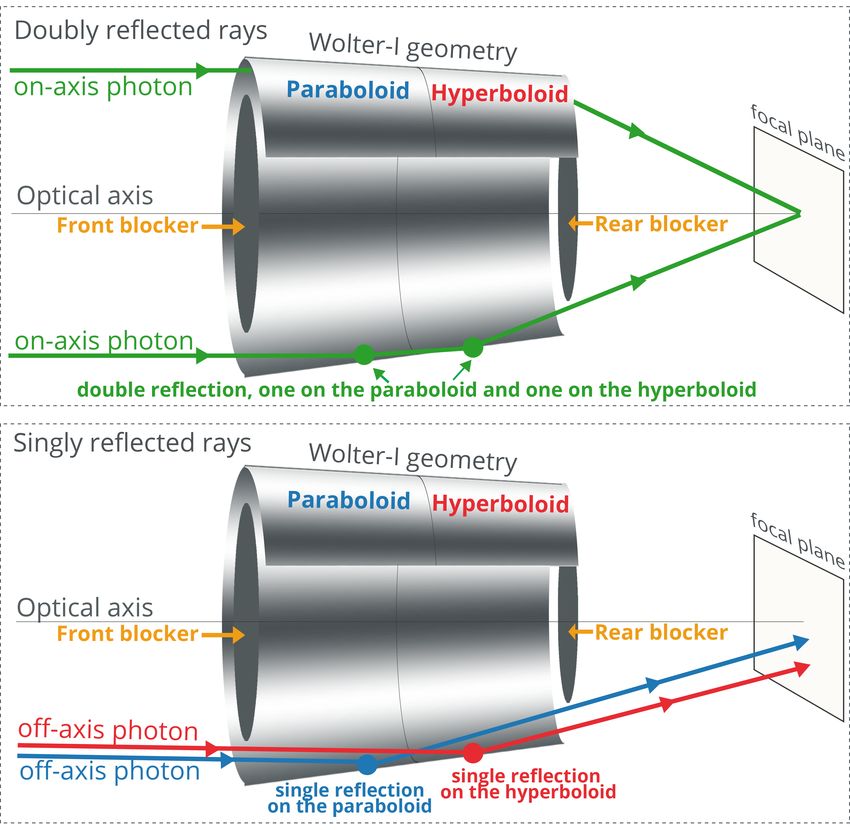
Figure 1. A Schematic of a Wolter-I monolithic mirror shell with the parabolic and hyperbolic reflecting
surfaces showing the difference between on-axis rays (green) that reflect on both mirror surfaces and those
off-axis rays (red and blue) that only reflect off of a single mirror surface. The optical axis is depicted as
a perpendicular line to the focal plane that goes through the center of the optics. In the top panel, on-axis
photons reflect first on the paraboloid segment then on the hyperboloid section and come to a focus on the
focal plane. These are referred to as doubly reflected focused rays. Blockers are primarily used (front and rear
indicated by the yellow arrows) to block rays which would go straight through the module without reflecting
off either surface and reach the focal plane. In the bottom panel, Singly reflected rays coming from off-axis
angles interact only with a single mirror surface (either the paraboloid, blue rays, or hyperboloid, red rays,
segment) and can make it to the focal plane. These singly-reflected rays are frequently referred to as ghost
rays because they can lead to unfocused patterns on the focal plane. The blockers can also reduce the amount
of ghost rays by limiting the angles accessible by off-axis rays to reflect off of mirror segments.

 –2–
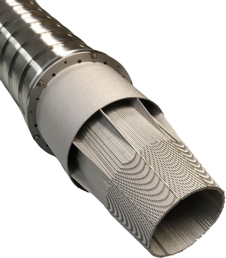
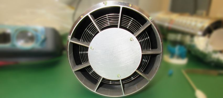
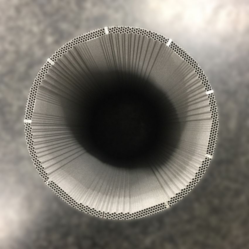
Figure 2. Photograph of the front of a FOXSI sounding rocket telescope module nesting 7 Wolter-I mirrors
shells. The circular front blocker is clearly visible and a spoked structure is used to hold and maintain
alignment of each mirror shell with respect to the others.

when pointing at a target of interest and can generate ghost rays which may obscure the emission
from the primary target, deteriorating the performance of a solar telescope. Previous missions have
minimized ghost rays by, for instance, tightly packing and nesting the mirror shells to block the paths
of ghost rays as in the case of the Nuclear Spectroscopic Telescope Array (NuSTAR) [7], through a
set of concentric circular sieves at the telescope aperture, in the case of Simbol-X [8], or by using
a pre-collimator as described by Spiga [9]. In this paper, we describe a number of approaches
to mitigate ghost rays that were developed, simulated, and tested for the FOXSI sounding rocket
payload. Since the FOXSI science goals require high sensitivity and dynamic range, understanding
and mitigating ghost rays is crucial to substantially improve its science. In order to verify these
approaches a new open source ray tracing simulation tool was developed which is also introduced
here.

2 The foxsisim ray-tracing Simulation

In order to verify and validate the properties of grazing-incidence optics and ghost-ray mitigation
strategies, we created and optimized a ray-tracing simulation capability. This tool is referred to as
foxsisim, though it is generic and can be used for many different grazing-incidence configurations.
Written in Python, the source code is open source and available on Github1[10]. The software is
provided as a Python package with documentation and also provides a simple graphical user
interface. The foxsisim package provides a class-based approach to ray-tracing. Figure 3 shows
a flow diagram representing the functional structure of foxsisim.
 The Module class uses a Surface subclass, which represents any optical surface with which
rays may interact. Such a surface is generally represented by a parametric equation in 3 dimensional
space. The SegmentH and SegmentP are subclasses of Surface and represent hyperboloid and
 1https://github.com/foxsi/foxsi-optics-sim

 –3–
SOURCE OPTICAL MODULE DETECTOR
 [Reflective surfaces] Position
 FOXSISIM
 Position
 Position Size
 Size • List of Rays with
 Geometry
 Spectrum - Wolter-1 or conic - History of positions
 [Origin, bounces, destination]
 - Length & radii
 - Energy
 - Focal distance
 - Blockers (radii) - Number of bounces
 - Alive/dead by absorption
 Reflectivity
 • Detector image
 Function Function Function

 Generate Rays Pass Rays Catch Rays Products

Figure 3. The flow diagram for the functional structure of the foxsisim ray-tracing simulation tool.
The code has three basic classes: Source, the source of x-rays, optical Module (a telescope module), and
a Detector. For each component in the simulation, a set of initialization parameters need to be defined.
Some examples are shown here which include position, size, spectrum of a source or reflectivity of an optical
surface. Source implements a function to generate a list of random rays. The pass rays function defined
by Module computes the interactions of rays with the module. Finally, the Detector class implements a
catch function which computes which rays land on the detector. The final output is a list of all rays with
keywords defining their position histories, their energy, their number of reflections, and a tag indicating
whether or not a ray was absorbed on a non-reflecting surface.

parabolic mirror segments respectively. A Shell class holds both reflecting segments and therefore
represents a telescope shell. Finally a full telescope module is potentially composed of many shells
and is represented by a Module class. An X-ray source is implemented in the Source class which
implements both isotropic sources as well as sources of perfectly parallel beams. The geometric
rays which represent the X-rays themselves are implemented by the Ray class. A casting function
finds the solution of rays reflecting off of or being stopped by surfaces (reflecting or non-reflective).
The spectral properties of the telescope are computed through its reflectivity, which depends on the
incoming ray angle. foxsisim uses Iridium surfaces with 10Å roughness to compute reflectivities.
Finally, a Detector class is used to capture the rays at a particular point in space and create an
image. The current implementation does not consider any random scattering off of surfaces, detector
efficiency, nor prioritize speed, though a future release is planned to address these issues.

3 The FOXSI sounding rocket payload and ghost rays

The FOXSI sounding rocket program is a mission to develop and test grazing-incidence optics
for solar observations. FOXSI uses a set of 7 Wolter-I figured grazing-incidence X-ray telescope
modules to perform imaging spectroscopy of solar hard X-rays from ∼ 4keV to ∼ 20keV [11, 12].
The parameters of the optics, such as diameters and focal length, were set to suit the payload of a
Terrier-Black-Brant sounding rocket. These optics were produced at NASA Marshall applying a low-
cost electroformed nickel alloy replication process, whereby nickel mirrors are electro-deposited
onto super-polished mandrels. For increased effective area, shells of various radii are coaxially
nested together into modules of 7 or 10 mirrors. The averaged resolution of the integrated modules
was measured in the laboratory to be 4.3±0.6 arcsec (FWHM) and 27±1.7 arcsec (half-power

 –4–
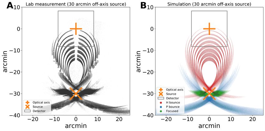
diameter; HPD) for an on-axis source ([12, 13]. A primary advantage of this production method
NASA Marshall uses is that multiple mirrors can be fabricated via replication by using a single
mandrel, which substantially lowers the cost of producing identical optics. A detailed description
of how these optics are fabricated can be found in [14] and [15]. The payload uses seven 60 cm
long telescope modules, each one containing 7 or 10 concentrically nested Wolter-I mirror shells,
all with a focal length of 2 m. The mirrors are optimal for graze angles ranging from 0.23 to 0.37
degrees. Constrained to the FOXSI Si detector square area, the field of view (FOV) is 16 × 16
arcmin2 . Each optical module includes circular blockers at the front and rear apertures added as a
baseline to mitigate straight-through and some ghost rays (see diagram and photograph in Figures 1
and 2, respectively). The circular blockers are 1.55 mm thick aluminum disks with 37.5 mm (front)
and 31.4 mm (rear) radii for a 7-mirror module, and with 31.0 mm (front) and 26.2 mm (rear) radii
for a 10-mirror module.
 A number of papers in the literature provide background on this experiment. Krucker et al.
[12, 16] describe the original payload and first scientific results of the mission. Glesener et al.
[17] provides an overview of the first two flights of the experiment. Christe et al. [13] describes
major updates made for the second flight as well as details on the mirror shell prescription. Musset
et al. [18], Athiray et al. [19] and Furukawa et al. [20] describe the hardware upgrades for the 3rd
flight of the sounding rockets. This paper is a continuation of the work described in Buitrago-Casas
et al. [21] which describes implementations to reduce singly-reflected X-rays. Outstanding sciences
results based on FOXSI’s observations are reported by Ishikawa et al. [22], Athiray et al. [23].
 FOXSI’s science objectives require high sensitivity and dynamic range observations of the Sun;
therefore understanding and mitigating ghost rays is essential. In order to characterize the patterns
generated by off-axis sources, a number of measurements were performed on individual telescope
modules at the NASA Marshall Stray Light Facility (SLF). The SLF consists of a 100 m evacuated
beam line. An optics module is placed inside an evacuated chamber at one end of the facility. Two
stages enable the optic to be rotated with a precision down to ∼ 3.5 arcsecs. The optics module
is then illuminated by a Trufocus 50 keV X-ray generator with a molybdenum target located at the
other end of the facility. A cooled Andor CCD iKon-L camera is located at the focal plane. The
Andor CCD camera consists of a 204y8×2048 array of pixels, with a pixel pitch of 13.5 microns.
This pitch translates to a resolution of 1.3 arcseconds and a measurement field of view (FOV) of
44.4×44.4 arcminutes, much larger than the FOXSI detector field of view. Since the X-ray source
cannot be moved, the optic is rotated to simulate rays coming from off-axis positions.
 Figure 4 shows an example of a ghost ray pattern from an off-axis X-ray source 30 arcmin away
from the optical axis. Panel A shows an actual measurement taken at the SLF with the Andor CCD
camera. The gray box shows the limited FOXSI field of view with the optical axis (orange cross)
at its center. The position of the off-axis source is shown by an orange X mark. A complex ghost
ray pattern was measured which is a result of singly-reflected rays from both the hyperboloid and
paraboloid mirror shell segments. In this case this is a 10-shell telescope. Each shell creates an
individual ring pattern which extends onto the FOXSI field of view. Notches in the rings are caused
by the spider spokes which hold the shells seen in Figure 2.
 Panel B in Figure 4 shows the results of a foxsisim ray-tracing simulation which compare
well with the measured ghost ray pattern. The simulated image is color-coded to show rays that
are doubly-reflected (green), reflected only by the hyperbolic segments (red), and reflected only

 –5–
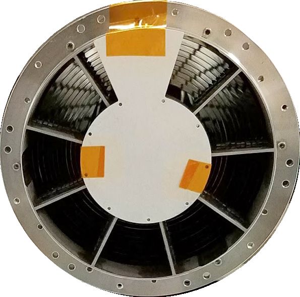
Figure 4. The ghost ray image from an X-ray source 30 arcmin off-axis for a 10-shell optics module. In both
panels, the grey square represents the on-axis FOXSI field of view. At the center, the optical axis is shown as
the orange cross. The location of the off-axis source is denoted by the orange X. Panel A: A measured ghost
ray image produced by a 10-shell optics module for a source located 30 arcmin off-axis. Data were acquired
at the NASA MSFC 104 m Stray Light Facility using a 2048 by 2048 pixel CCD detector placed at the focal
plane. Panel B: Simulated ghost rays produced by the foxsisim ray-tracing code. The green portion of the
pattern corresponds to doubly-reflected rays while the blue and red areas are the patterns generated by the
paraboloid and the hyperboloid segments, respectively.

by the parabolic segments (blue). The major features in the ghost ray patterns are rings, one for
each of the ten mirror shells. The vertical gap in the rings are caused by one of the spider spokes
(seen in Figure 2) which partially block the shells. These are not included in the simulation. The
blockers are included in the simulation and block some of the ghost rays. A first order quantifiable
comparison of the lab data with the simulation was done by measuring the distance from the source
location to each of the rings in the patterns. Such comparison shows differences always under ∼ 3%
for all the rings of the lab data compared to the ones for the simulation.

4 Use of foxsisim to study FOXSI ghost-rays

4.1 Ghost rays as function of off-axis angle
With the simulation validated and in order to gain a better intuition for how ghost rays evolve as a
function of off-axis angle, the simulation was run for a variety of off-axis angles. The results are
shown in Figure 5 for off-axis angles 0, 4, 8, 12, 16, 20, 24, 28, and 32 arcmin away from the optical
axis. It can be seen that as soon as the source is moved off-axis, a ghost-ray pattern emerges but at
large angular distances away from the focal plane. These rays do not (yet) infringe on the detectors
plane. As the source moves further off-axis, these ghost rays change shape and eventually begin
to be seen on the focal plane between 12 and 16 arcmin. A more precise analysis shows that the
threshold for ghost rays to impact the detect plane is at 13 arcmin off-axis for a 10-mirror optics

 –6–
module, and 18 arcmin off-axis for a 7-mirror optics module. This difference is due to the fact that
most ghost rays originate from the inner most mirrors of the optics. A 10-mirror optics module
includes three additional smaller mirrors to the standard configuration of a standard 7-mirror optics
module, as described in Christe et al. [13].

Figure 5. Simulated ghost ray images for a 10-shell module as a function of off-axis angle for a source at
infinity from 0 to 32 arcmin. The gray square shows the field of view of the FOXSI detectors. The orange
symbols show the optical axis and source position. As the source moves away from the optical axis ghost
ray patterns appear, at first outside of the detector-bounded field of view. Between 12 and 16 arcmin, these
rays begin to infringe on the detector area. The detector-integrated ghost ray flux contamination continues to
increase as the pattern increases in size and complexity.

4.2 Ghost rays energy dependence
The reflectivity of a Wolter-I mirror depends on the angle of incidence, the surface material, and
roughness of the mirror [24]. The FOXSI optics uses electroformed nickel mirrors coated with a

 –7–
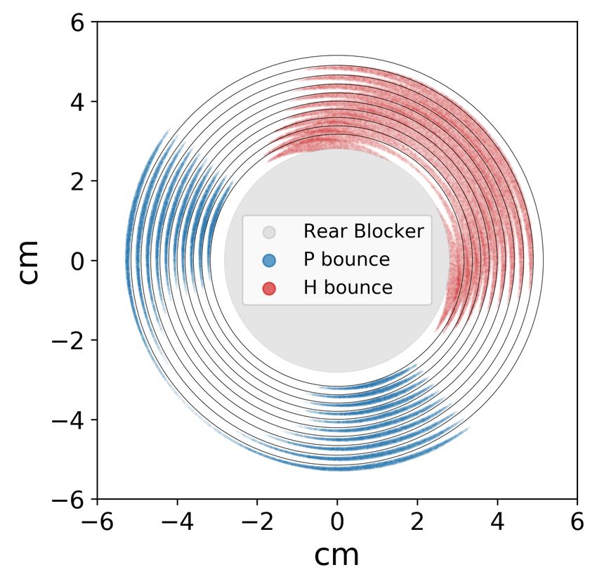
thin layer of iridium. For the simulation, we use the theoretical reflectivity of Iridium with a surface
roughness of 10Å2. Compared to focused rays, ghost rays are generated from rays at large angles yet
they are only reflected once so that it is not straightforward to understand their energy dependence.
To investigate this, we simulated the energy response of ghost rays.
 Figure 6 shows the simulated energy dependence of the effective area with energy for doubly-
and singly- reflected rays generated by an on-axis source, an off-axis source at 20 arcmin (solid
lines), and an off-axis source at 28 arcmin (dashed lines) on a 10-mirror optics integrated over the
detector field of view. The input spectrum is assumed to be constant from 0 to 30 keV. On the left
panel of figure 6, the y-axis is normalized to focused flux at 1 keV (green curve), and it is plotted
in log scale. For both panels, the solid blue (red) lines correspond to the paraboloid (hyperboloid)
ghost rays reaching the detector area coming from a 20 arcmin off-axis source. The dashed red line
corresponds to hyperboloid ghost rays coming from a 28 arcmin off-axis source. The left panel
shows that ghost ray fluxes are generally two orders of magnitude smaller than the flux from an
on-axis source. On the right, the fluxes are all normalized to each other to better compare the energy
dependence. From this panel, it is clear that , above ∼6 keV, the ghost ray flux falls off significantly
faster than for focused rays. This behavior is even more dramatic for those rays that singly reflect
off of the paraboloid. This simulation allow us to conclude that ghost rays provide only a small
contribution to the background and are negligible for source-dominated observations. Furthermore
their contribution to the background is reduced at high energies.

 0
Normalized to focused on-axis

 10 1.0 Focused rays on-axis
 H bounced rays 20arcmin
 Individually normalized

 P bounced rays 20arcmin
 H bounced rays 28arcmin
 0.8
 1
 10
 0.6
 2
 10 0.4

 Focused rays on-axis
 H bounced rays 20arcmin 0.2
 3
 10 P bounced rays 20arcmin
 H bounced rays 28arcmin
 0.0
 0.0 2.5 5.0 7.5 10.0 12.5 15.0 17.5 20.0 0.0 2.5 5.0 7.5 10.0 12.5 15.0 17.5 20.0
 Energy [keV] Energy [keV]

Figure 6. The simulated energy response for a point source with a flat spectrum from 0 to 30 keV integrated
over the detector field of view from an on-axis (green solid line), 20 arcmin (solid red and blue lines), and 28
arcmin (dashed red line) off-axis. Blue and red lines represent singly-reflected rays from the paraboloid and
hyperboloid segment, respectively. Left. Detector-integrated fluxes normalized to the focused on-axis (solid
green line) at 1 keV. The singly-reflected flux intensity is found to be two orders of magnitude smaller than
the focused intensity. Right. The same curves from the left but normalized to each other to better compare
the energy dependence. It can be seen that the ghost ray intensity falls off significantly faster than the focused
rays. This is most pronounced for those singly-reflected rays from the paraboloid segment.

 An analog analysis of ghost rays dependence on off-axis angles and energy, but scaled up to a
satellite mission, is presented in appendix A of this paper.

 2http://henke.lbl.gov/optical_constants/

 –8–
5 Ghost Ray Mitigation Strategies

In this discussion we explore a number of different strategies to reduce the intensity of ghost rays.

5.1 Circular Blockers

The concept of circular blockers has already been introduced in section 3. These blockers located at
the entrance aperture and exit primarily stop X-rays from traveling through the center of the optics.
The back aperture blocker also serves to remove some ghost rays. In this section, we investigate
the optimization of the size of these blockers, both front and rear. For optimized blockers, fewer
ghost rays reflected from the hyperboloid segments make it onto the detector. If not correctly sized,
small blockers can allow some paraboloid reflected ghost rays to reach the detector area. On the
other hand, if the blockers are too large, the focused rays from the smallest mirror are blocked.
Optimizing their design is crucial to improve the overall performance of the telescope.
 Figure 7 shows the impact of different front and rear blocker sizes on a 10-mirror optics module,
as a function of the off-axis source location. The y-axis in all plots shows the intensity of rays
within the detector, normalized to the maximum flux of doubly reflected rays, i.e. when the sources
is on-axis. The top panels show the effect on the focused rays (green); the panels on the left present
the impact of front blocker sizes on focused rays, singly reflected rays from paraboloid segments
(blue curves on the top and middle panels), and singly reflected rays from hyperboloid segments
(red curves on the top and bottom panels). For all three panels on the left, front blocker radii range
among 2.875 cm, 3.0967 cm, 3.1334 cm and 3.1700 cm, while there is no rear blocker. The panel
at the top-left displays focused (green) and singly reflected (blue and red) rays together to show the
relative flux of ghost rays when compared to focused rays. It is observed that ghost ray fluxes never
surpass 35% of the on-axis focused flux.
 According to the left panels of figure 7, it is clear that the larger the front blocker, the less ghost
rays impinge into the detector. However, the larger the front blocker, the larger is the reduction
effect on the focused rays. An optimized size must balance reducing singly-reflected rays while
having the smallest effect on focused rays. In this case, the best size was found to be 3.0967 cm,
and 3.7494 cm radius for a 10-mirror and a 7-mirror optics module, respectively.
 The three panels on the right of figure 7 assess the effect of the rear blocker on the ghost ray
background for the innermost mirror of a 10-mirror optics module. In this case, the front blocker
was set to a constant radius of 3.0967 cm (optimized size found for the front blocker). These three
panels on the right have an analogous structure to the left panels. For the rear blocker, the best
trade-off between reducing ghost rays and minimizing vignetting effects is obtained for a radius
of 2.62 cm for a 10-mirror optics. An analogous simulation was run for the innermost mirror of
a standard 7-mirror optics (not shown here) leading to a radius of 3.14 cm radius as an optimal
parameter for the rear circular blocker.
 Blockers with optimal sizes were manufactured and implemented on the FOXSI-3 rocket
payload. The effectiveness of this strategy was demonstrated with direct lab measurements shown
in Figure 8 A, which shows the pattern on the focal plane generated by a 30 arcmin off-axis source
shining on a 7-mirror module placed at the NASA Marshall SLF. From Figure 8 A it is concluded that
ghost rays are highly mitigated within a detector (gray box on the figure) by simply implementing

 –9–
Front blocker size dependence (No Rear Blocker) Rear blocker size dependence (FB radius = 3.0967cm)
 1.0 Focused - FB radius=2.8575cm Focused - RB radius=0.00cm
 Focused - FB radius=3.0967cm Focused - RB radius=2.62cm
 Focused - FB radius=3.1334cm Focused - RB radius=2.64cm
 Focused normalized intensity

 0.8 Focused - FB radius=3.1700cm Focused - RB radius=2.66cm
 Focused - RB radius=2.68cm

 0.6

 0.4

 0.2

 0.0
 P bounce - FB radius=2.8575cm P Bounce - RB radius=0.00cm
H bounced rays normalized to Focused max P bounced rays normalized to Focused max

 0.30 P bounce - FB radius=3.0967cm P Bounce - RB radius=2.62cm
 P bounce - FB radius=3.1334cm P Bounce - RB radius=2.64cm
 0.25 P bounce - FB radius=3.1700cm P Bounce - RB radius=2.66cm
 P Bounce - RB radius=2.68cm
 0.20
 0.15
 0.10
 0.05
 0.00
 H bounce - FB radius==2.8575cm H Bounce - RB radius=0.00cm
 0.12 H bounce - FB radius=3.0967cm H Bounce - RB radius=2.62cm
 H bounce - FB radius=3.1334cm H Bounce - RB radius=2.64cm
 0.10 H bounce - FB radius=3.1700cm H Bounce - RB radius=2.66cm
 H Bounce - RB radius=2.68cm
 0.08
 Si Detector Diagonal = 11.91"

 Si Detector Diagonal = 11.91"
 Si Detector Edge = 8.25"

 Si Detector Edge = 8.25"

 0.06
 0.04
 0.02
 0.00
 0 5 10 15 20 25 0 5 10 15 20 25
 Off-axis angle [arcmin] Off-axis angle [arcmin]

Figure 7. Use of foxsisim to study the effect that the front (three panels on the left) and the rear (three
panels on the right) circular blockers have on focused and ghost rays. The simulation was run for a source
at infinity varying its position from on-axis to 28 arcmin off-axis (the horizontal axis of every plot). The
simulated optics consisted of a single shell with physical parameters (radii and focal length) of the innermost
mirror from a standard 10-shell optic. A standard detector size was used for these simulations (1cm side).
We utilized source off-axis positions ranging along a direction defined by the diagonal of such detector. Plots
at the top row show focused (green), and ghost rays in blue (red) coming from the paraboloid (hyperboloid)
segment. All plots are normalized to the focused flux of an on-axis source. Plots on the second (third) row
show singly reflected rays fluxes coming from the paraboloid (hyperboloid) segment. The line style for every
curve corresponds to a particular set of blocker radii, as indicated at the legends. The gray dashed vertical
lines indicate the minimum (left) and maximum (right) distance from the optical axis to the edge of the
squared detector.

 – 10 –
the right blocker sizes. For the third flight of the rocket, all optical modules were upgraded to have
optimized blockers, which is now a baseline for FOXSI and should be for future Wolter-I optics.
 The foxsisim toolkit was extensively utilized before the FOXSI-3 rocket campaign to ascertain
efficient methods of mitigating ghost rays. In this section, it was shown that optimizing the front and
rear blocker sizes is a simple way to minimize ghost rays on the detectors. Although the blockers
substantially reduce ghost rays, this strategy does not eliminate all of the ghost ray background.
Two additional strategies to further decrease ghost ray background are discussed next.

5.2 Honeycomb collimator

Another method to reduce singly-reflected rays is to collimate rays before they arrive at the entrance
aperture. Figures 5 and 7 show that, for a 10-mirror optics, ghost rays are produced by off-axis
sources beyond ∼ 13 arcmin. For a 7-mirror optic only rays beyond ∼ 18 arcmin make it onto the
detector due to the larger graze angles. In order to remove these rays a collimator was designed and
tested. A photograph of this collimator is shown in Figure 8 panel C. This honeycomb collimator
was 3D printed and consists of a series of parallel, cylindrical, and uniform holes or channels through
which X-rays can pass. The longer and thinner the channels, the smaller the angle of acceptance for
X-rays and therefore the greater the collimation. The thickness of the walls of the channels must be
large enough stop (absorb) the pertinent X-ray energies (up to ∼20 keV in this case). The thicker
the channel walls the larger the reduction of aperture. Since most of the detector-infringing singly-
reflected rays come from the inner mirrors, the structure only collimates the four innermost mirrors
of a 7-shell optical module, which helped minimize weight. For the large radii mirror shells, less
collimation is necessary leading to a reduction in the required channel height at the circumference.
The final version of the collimator has a maximum length of 19.5 cm, and 1 mm diameter channels
with 120-micron-thick walls between the channels in a hexagonal structure. Further details on the
manufacture and dimensions of this collimator can be found in section 3.2 of Buitrago-Casas et al.
[21].
 The effectiveness of the collimator was tested at the MSFC SLF facility. The results can be seen
in Figure 8 for a collimator optimized for a 7-mirror optic. Panels A and B compare the ghost-rays
with and without the collimator for a source 30 arcmin off-axis showing a clear reduction in ghost
rays. It can be seen that the collimator removes many ghost rays from the detector. The pay-off is
a reduction of focused rays which depends on the open area of the collimator cross-section. The
thin outermost ring observed in Figure 8 B is due to a narrow gap between the innermost part of
the honeycomb structure of the collimator and the front blocker. This gap can easily be removed by
adjusting the size of the blockers in future design iteration leading to an image with no ghost rays.
 An important limitation of the honeycomb collimator is that this strategy does not block ghost
rays near the source for long focal lengts missions (e.g. focal lengths of 10 m or longer).

5.3 Wedge Absorber

The distribution of singly-reflected rays on the aperture plane suggests another method to reduce
ghost rays. From Figure 9 Panel A, it is observed that singly reflected rays from the paraboloid
segments (blue) and from the hyperboloid segments (red) come from different and confined angular
areas of the mirrors. Since it is known that the primary source of ghost-rays are reflections from

 – 11 –
C 3D printed honeycomb collimator D Honeycomb collimator front view

 Front

Figure 8. Measured mitigation of ghost rays for a 30 arcmin off-axis X-ray source shining on a 7-mirror
module at the NASA Marshall SLF. A shows the ghost-rays measurement displayed over the focal plane
when optimized blocker sizes are used for the optics module. B shows how by using blockers together with
a honeycomb collimator, all ghost rays can be removed. The thin outer-most ring on the ghost ray pattern
is due to X-rays that leak through a narrow gap between the front blocker and the collimator structure. Due
to mechanical constraints, we had to use a slightly smaller blocker than the one used on panel A, so that it
could be physically attached to the collimator. This gap can easily be reduced to zero to remove all ghost rays
from the field of view for future missions. Panels A and B display an orange cross and X mark representing
the optical axis and source location, respectively. The gray box shows a detector. C presents a picture of
the actual honeycomb collimator attached to the entrance of one 7-mirror optics module. D shows a head-on
view of the collimator and shows the honeycomb structure designed to collimate rays in front of the four
innermost mirrors. Every small hexagonal hole has a 1 mm diameter and a wall thickness of 0.12 mm. The
honeycomb collimator’s length is 20.05 cm, which translates to an aspect ratio of up to 200.

 – 12 –
A Simulated optics cross-section
 ur
 so
 ce
 B Wedge Absorber photograph

C Wedge Absorber effect on focal plane
 D Schematic layout of the wedge absorber

Figure 9. A wedge absorber is a successful strategy to clear detectors of ghost ray background when
a compact and intense off-axis X-ray source is present. (A) Cross-section of an optics module showing
the spatial distribution of simulated singly reflected rays differentiated by color. The paraboloid (blue)
and hyperboloid (red) singly reflected rays come from different regions of the optic. (B) Photograph of
an aluminium 1.5 mm thick wedge absorber tightly placed at the entrance of a 10-mirror module. That
optics + wedge absorber was tested at the NASA Marshall SLF. (C) Measurement of effect that the wedge
absorber has on the focal plane pattern when a 30 arcmin off-axis X-ray source illuminates the module at the
NASA Marshall SLF. The orange cross and X mark represent the optical axis and the location of the source
respectively. The gray box represents a standard detector. As observed in panel C, ghost rays impinging a
detector are negligible when implementing the wedge absorber strategy. In panel D, we display a schematic
layout for the wedge absorber, made out of a 1.5 mm thick aluminum plate. The wedge disk’s center needs
to be placed at the optics entrance, in line with the optical axis. The wedge must be clocked according to the
X-ray source’s location. This wedge blocks all of the rays singly-reflected from the hyperbolic section.

 – 13 –
the hyperboloid segments these can be blocked at the aperture with a wedge-shaped absorber, a
photograph of which can be seen in Panel B in front of a 10-mirror module. This method was tested
at the MSFC SLF with a 30 arcmin off-axis source. The pattern on the focal plane is observed
to be completely clear of ghost rays. The downsides of this method are that the focused rays are
reduced by the wedge and that the angle of the absorber must be opposite to the polar angle of the
source. This means, that it is required to know of the ghost ray source location in advance and to
have control of the wedge angle.

5.4 Comparing ghost ray mitigation strategies
A number of strategies are discussed and compared in this section. The first strategy, blockers,
was found to effectively reduce ghost rays though they must be optimized. Using the simulation, it
is possible to find an optimal size for the blockers that reduces a large amount of ghost rays with
minimal impact on focused rays. The use of optimized blockers should be implemented as a
baseline for any Wolter-I telescope design.
 The effectiveness of the other two strategies considered in this paper to mitigate ghost rays, the
wedge absorber and honeycomb collimator, are compared in Table 1. This trade-off study contains
parameters assessing effects on the optical performance of the instrument like the efficacy at reducing
ghost-rays, and degradation of the telescope effective area. We also compare the implication of
each strategy on their fabrication and coupling with other parts of a potential mission. The last part
of the table evaluates the possible heritage use of these two strategies for future missions.
 One important limitation of the wedge absorber is that the angle of the wedge must be set in
accordance with the polar angle of an off-axis source. In the right configuration, it may be possible
to block ghost-rays from many sources but generally a wedge absorber can only deal with a single
source. The orientation of the wedge could be tuned by either rotating the entire observatory or
by adding a mechanism to rotate the wedge. A mechanism could also potentially control multiple
wedges that could block multiple sources and stow under each other to return to a single wedge
configuration.
 There have been several X-ray telescopes with Wolter-I mirrors that have had to deal with
ghost rays. All were designed to observe astronomical objects, like Chandra, XMM Newton, and
NuSTAR. The latter have been used to observe the Sun where the ghost ray situation is much more
intense. Chandra and XMM Newton implemented methods to minimize, but not completely block,
ghost rays. NuSTAR had some launch mass constraints that led to abandoning a collimator designed
to mitigate stray light and ghost rays optimally.
 Chandra suppressed ghost rays within 14 arcmins of the optical axis by placing monolithic
baffles at the very front of the telescopes and the optics’ central aperture plate’s aft surface. A
description of the baffles is given in Cusumano et al. [8], and Gaetz et al. [25]. XMM Newton also
implemented X-ray baffles, but different from Chandra’s. They were constructed as a series of sieve
plates made out of rigid circular strips. These sieves were aligned and mounted to the front face
of each telescope module. The axial space available allowed two of such sieves to be incorporated
instead of monolithic baffles, blocking ∼ 80% of ghost rays. The sieves designed for XMM Newton
block singly reflected rays from just outside the nominal optics FOV (cone angle of 15 arcmins). A
detailed description of this method is discussed in de Chambure et al. [26]. NuSTAR is affected by
stray light and ghost rays. Madsen et al. [7] discuss how NuSTAR ghost rays and stray light could

 – 14 –
have been prevented and should be in future observatories. For NuSTAR, some ghost ray mitigation
was achieved using a compact shell spacing. Madsen et al. [7] indicate that to reduce further ghost
rays, baffling of some sort is required.
 In general, for Wolter-I telescopes with enough space between mirrors, ghost rays can be
controlled by baffling within the optics, as fully described by Gaetz et al. [25]. But, highly nested
telescopes are challenging to baffle via this method due to the limited space between consecutive
mirrors, which is the case for FOXSI. Using monolithic cylindrical baffles at the entrance of every
mirror is another method to constrain ghost rays useful only for highly packed Wolter-I mirrors
designed for a rather large grazing incidence angle. FOXSI’s angles range from 0.23 to 0.37
degrees, with mirror spacing of 0.1-0.2 cm, this translates monolithic cylinders over 50 cm long to
block ghost rays entirely. Such long cylinders would have been very challenging to manufacture and
attach to each shell and would have doubled the length of the optics. For FOXSI, we also discarded
sieves’ use since they mitigate but not entirely block ghost rays. We had to develop new ghost ray
blocking strategies, leading to the 3D honeycomb collimator and the wedge absorber presented in
this paper and summarized in Table 1.

6 Summary and Conclusions

All strategies to mitigate ghost rays presented here were established by a comprehensive use of
foxsisim. The mission of analysing ghost rays, and reducing them, was an excellent example to
show the versatility and power of our ray tracing simulation toolbox. We present foxsisim as
an open-access set of tools to study any X-ray Wolter-I optics. We encourage the broad scientific
community to use the numerical tools presented here. They can be useful in applications for
astronomy, medicine, material sciences, etc. Future scientific results of the quiet-Sun observations
obtained during past flights of the FOXSI rocket will include the use of foxsisim to assess the
overall instrument background.
 We found that adding blockers optimized to maximize their ghost-ray mitigation should be a
baseline for any Wolter-I telescope design. In addition, we assessed two other strategies to reduce
ghost-rays. One based on a honeycomb collimator and one on a wedge absorber. The use of either
of these two strategies on future spacecrafts imply some payoff that need to be assessed according
to the particular design and constrains of the instrument. For example, a honeycomb collimator
adds a substantial amount of mass but requires minimum, if any, maneuvering. Opposite to that,
the wedge absorber is light, but requires telemetry and control of the spacecraft to locate the wedge
at the right position that optimizes ghost ray mitigation. The two strategies have a direct impact on
the effective area of the optics.

Acknowledgments

The first author of this paper is funded by the NASA FINESST grant 80NSSC19K1438. The
FOXSI-3 sounding rocket is funded by NASA LCAS grant NNX16AL60G. UMN team members
were supported by the NSF grant AGS-1429512. Japan team members were supported by JSPS
KAKENHI Grant Numbers JP15H03647, JP18H03724. The FOXSI team is grateful to the NSROC
teams at WSMR and Wallops for the excellent operation of their systems. Furthermore, the authors

 – 15 –
Parameter Wedge absorber 3D printed honeycomb colli-
 mator
 Efficacy at reducing singly re- Depending on the spatial config- Nominally close to 100% for the
 flected rays uration of the source(s) the ef- graze angles of the original de-
 ficacy ranges from ∼ 0% up to sign.
 ∼ 100%
 Volume and weight Minimal Length and mass scale inversely
 with threshold off-axis angle
 blocked. FOXSI design (18 ar-
 cmin threshold) is 19.5 cm long,
 has an internal radius of 4.43 cm,
 an external radius of 5.3 cm, and
 a mass of 0.8 kg.
 Fabrication constraints Mechanically easy to implement, 3D printing allows for easy cus-
 with a material dense enough to tomization of the design to min-
 stop X-rays in the working en- imize mass, but technology is
 ergy range of FOXSI currently limited to channels no
 smaller than 0.5 - 1 mm.
 Calibration difficulties Need to characterize the effect It needs to be guaranteed that the
 that the wedge absorber has on optics module and collimator op-
 the point spread function. tical axes are co-aligned. Sys-
 tem mis-alignments lead to a vast
 degradation of the telescope ef-
 fective area and ghost rays.
 Implications on other parts of the Precise non-trivial roll con- Some implications on the loca-
 payload trol during the rocket flight. tion of solar pointing sensors to
 These maneuvers require care- avoid interference. Extra diffi-
 ful telemetry command control culties at aligning the payload
 on the payload roll angle. due to the lack of ghost rays used
 in such process.
 Mechanical implications It should be well attached to the Minor implications mostly due to
 FOXSI spider fixture to keep in the co-alignment of the collima-
 place during the flight. tor mounting with a FOXSI tele-
 scope.
 Heritage to satellite missions Applicable with substantial mod- If the honeycomb structure is re-
 ifications to allow angular mo- duced in size it may become an
 bility of the blocker. Includes option for a spacecraft, but it can
 extra complexity on electronics, not block small off-axis anlges.
 power, and controller logic. A
 protocol to decide placement of
 the wedge need to be set.

Table 1. Comparison of the two strategies considered to reduce singly reflected rays for the FOXSI rocket
experiment.

 – 16 –
would like to acknowledge the contributions of each member of the FOXSI experiment team to
the project, particularly our team members at MSFC for the fabrication of the focusing optics.
Thank-you to Amy Winebarger and Patrick Champey, and Wayne Baumgartner at the MSFC for
their grand disposition when we were taking data at the Stray Light Facility. We also thank Robert
Taylor for initiating the writing of the foxsisim ray tracing simulation during a Summer internship
at the NASA Goddard Space Flight Center. The authors thank to Mr. Hayato Inuzuka and Mr.
Futoshi Yoshimura at Toray Precision Co., Ltd. for their great effort on the development of 3D
printed honeycomb collimator. The first author thanks Dr. Juan Carlos Martínez Oliveros for
fruitful discussions during the writting of this paper.

References

 [1] Hans Wolter. Zur frage des lichtweges bei totalreflexion. Zeitschrift für Naturforschung A, 5(5):
 276–283, 1950.
 [2] Webster C Cash. Medical uses of focused and imaged x-rays, March 19 2002. US Patent 6,359,963.
 [3] Yasushi Ogasaka, Keisuke Tamura, Ryo Shibata, Akihiro Furuzawa, Takuya Miyazawa, Kenta
 Shimoda, Yoshihiro Fukaya, Tomonaga Iwahara, Tomokazu Nakamura, Masataka Naitou, et al.
 Characterization of a hard x-ray telescope at synchrotron facility spring-8. Japanese Journal of
 Applied Physics, 47(7R):5743, 2008.
 [4] DFR Mildner and MV Gubarev. Wolter optics for neutron focusing. Nuclear Instruments and
 Methods in Physics Research Section A: Accelerators, Spectrometers, Detectors and Associated
 Equipment, 634(1):S7–S11, 2011.
 [5] Desiree Della Monica Ferreira, Finn E Christensen, Michael J Pivovaroff, Nicolai Brejnholt, Monica
 Fernandez-Perea, Niels Jørgen S Westergaard, Anders C Jakobsen, Marie-Anne Descalle, Regina
 Soufli, and Julia K Vogel. Hard x-ray/soft gamma-ray telescope designs for future astrophysics
 missions. In Optics for EUV, X-Ray, and Gamma-Ray Astronomy VI, volume 8861, page 886116.
 International Society for Optics and Photonics, 2013.
 [6] W Werner. Imaging properties of wolter i type x-ray telescopes. Applied optics, 16(3):764–773, 1977.
 [7] Kristin K Madsen, Finn E Christensen, William W Craig, Karl W Forster, Brian W Grefenstette,
 Fiona A Harrison, Hiromasa Miyasaka, and Vikram Rana. Observational artifacts of nuclear
 spectroscopic telescope array: ghost rays and stray light. Journal of Astronomical Telescopes,
 Instruments, and Systems, 3(4):044003, 2017.
 [8] Giancarlo Cusumano, MA Artale, T Mineo, V Teresi, Giovanni Pareschi, and V Cotroneo. Simbol-x:
 x-ray baffle for stray-light reduction. In Optics for EUV, X-Ray, and Gamma-Ray Astronomy III,
 volume 6688, page 66880C. International Society for Optics and Photonics, 2007.
 [9] Daniele Spiga. Analytical computation of stray light in nested mirror modules for x-ray telescopes. In
 Optics for EUV, X-Ray, and Gamma-Ray Astronomy VII, volume 9603, page 96030H. International
 Society for Optics and Photonics, 2016.
[10] Steven D. Christe, Milo Buitrago-Casas, and Robert Taylor. foxsi/foxsi-optics-sim, September 2019.
 URL https://doi.org/10.5281/zenodo.3445460.
[11] Sam Krucker, Steven Christe, Lindsay Glesener, Steve McBride, Paul Turin, David Glaser, Pascal
 Saint-Hilaire, Gregory Delory, R. P. Lin, Mikhail Gubarev, Brian Ramsey, Yukikatsu Terada,
 Shin-Nosuke Ishikawa, Motohide Kokubun, Shinya Saito, Tadayuki Takahashi, Shin Watanabe,

 – 17 –
Kazuhiro Nakazawa, Hiroyasu Tajima, Satoshi Masuda, Takashi Minoshima, and Masumi Shomojo.
 The Focusing Optics X-ray Solar Imager (FOXSI), volume 7437 of Society of Photo-Optical
 Instrumentation Engineers (SPIE) Conference Series, page 743705. SPIE, 2009. doi:
 10.1117/12.827950.
[12] Säm Krucker, Steven Christe, Lindsay Glesener, Shinnosuke Ishikawa, Brian Ramsey, Mikhail
 Gubarev, Shinya Saito, Tadayuki Takahashi, Shin Watanabe, Hiroyasu Tajima, et al. The focusing
 optics x-ray solar imager (foxsi): instrument and first flight. In Solar Physics and Space Weather
 Instrumentation V, volume 8862, page 88620R. International Society for Optics and Photonics, 2013.
[13] Steven D Christe, Lindsay Erin Glesener, Juan Camilo Buitrago-Casas, Shin-Nosuke Ishikawa,
 Brian D Ramsey, Mikhail V Gubarev, Kiranmayee Kilaru, Jeffery J Kolodziejczak, Shin Watanabe,
 Tadayuki Takahashi, Hiroyasu Tajima, Paul Turin, Van Shourt, Natalie Foster, and Sam Krucker.
 FOXSI-2: Upgrades of the Focusing Optics X-ray Solar Imager for its Second Flight. Journal of
 Astronomical Instrumentation, 5(1):1640005–1640625, March 2016.
[14] Brian D. Ramsey, Cheryl D. Alexander, Jeff A. Apple, Carl M. Benson, Kurtis L. Dietz, Ronald F.
 Elsner, Darell E. Engelhaupt, Kajal K. Ghosh, Jeffery J. Kolodziejczak, Stephen L. O’Dell, Chet O.
 Speegle, Douglas A. Swartz, and Martin C. Weisskopf. First Images from HERO, a Hard X-Ray
 Focusing Telescope. Astrophysical Journal, 568(1):432–435, Mar 2002. doi: 10.1086/338801.
[15] Brian D. Ramsey. Replicated Nickel Optics for the Hard-X-Ray Region. Experimental Astronomy, 20
 (1-3):85–92, Dec 2005. doi: 10.1007/s10686-006-9033-6.
[16] Säm Krucker, Steven Christe, Lindsay Glesener, Shin-nosuke Ishikawa, Brian Ramsey, Tadayuki
 Takahashi, Shin Watanabe, Shinya Saito, Mikhail Gubarev, Kiranmayee Kilaru, et al. First images
 from the focusing optics x-ray solar imager. The Astrophysical Journal Letters, 793(2):L32, 2014.
[17] Lindsay Erin Glesener, Sam Krucker, Steven D Christe, Shin-Nosuke Ishikawa, Juan Camilo
 Buitrago-Casas, Brian D Ramsey, Mikhail V Gubarev, Tadayuki Takahashi, Shin Watanabe,
 Shinichiro Takeda, Sasha Courtade, Paul Turin, Stephen McBride, Van Shourt, Jane Hoberman,
 Natalie Foster, and Juliana Vievering. The FOXSI solar sounding rocket campaigns. In Jan-Willem A
 den Herder, Tadayuki Takahashi, and Marshall Bautz, editors, SPIE Astronomical Telescopes +
 Instrumentation, page 99050E. SPIE, July 2016.
[18] Sophie Musset, Juan Camilo Buitrago-Casas, Lindsay Erin Glesener, Stephen Bongiorno, Sasha
 Courtade, P Subramania Athiray, Juliana Vievering, Shin-Nosuke Ishikawa, Noriyuki Narukage,
 Kento Furukawa, Daniel F Ryan, Greg Dalton, Zoe Turin, Lance Davis, Tadayuki Takahashi, Shin
 Watanabe, Ikuyuki Mitsuishi, Kouichi Hagino, Tomoko Kawate, Paul Turin, Steven D Christe,
 Brian D Ramsey, and Sam Krucker. Ghost-ray reduction and early results from the third FOXSI
 sounding rocket flight. In Oswald H Siegmund, editor, UV, X-Ray, and Gamma-Ray Space
 Instrumentation for Astronomy XXI, page 37. SPIE, September 2019.
[19] PS Athiray, Juan Camilo Buitrago-Casas, Kendra Bergstedt, Juliana Vievering, Sophie Musset,
 Shin-nosuke Ishikawa, Lindsay Glesener, Tadayuki Takahashi, Shin Watanabe, Sasha Courtade, et al.
 Calibration of the hard x-ray detectors for the foxsi solar sounding rocket. In UV, X-Ray, and
 Gamma-Ray Space Instrumentation for Astronomy XX, volume 10397, page 103970A. International
 Society for Optics and Photonics, 2017.
[20] Kento Furukawa, Juan Camilo Buitrago-Casas, Juliana Vievering, Kouichi Hagino, Lindsay Glesener,
 PS Athiray, Säm Krucker, Shin Watanabe, Shin’ichiro Takeda, Shin’nosuke Ishikawa, et al.
 Development of 60 m pitch cdte double-sided strip detectors for the foxsi-3 sounding rocket
 experiment. Nuclear Instruments and Methods in Physics Research Section A: Accelerators,
 Spectrometers, Detectors and Associated Equipment, 924:321–326, 2019.

 – 18 –
[21] Juan Camilo Buitrago-Casas, Lindsay Erin Glesener, Steven D Christe, Brian D Ramsey, Ronald
 Elsner, Sasha Courtade, Juliana Vievering, Athiray Subramania, Sam Krucker, Shin-Nosuke
 Ishikawa, Noriyuki Narukage, Paul Turin, and Sophie Musset. Methods for reducing singly reflected
 rays on the Wolter-I focusing mirrors of the FOXSI rocket experiment. In Giovanni Pareschi and
 Stephen L O’Dell, editors, Optics for EUV, X-Ray, and Gamma-Ray Astronomy VIII, pages 18–16.
 SPIE, September 2017.
[22] Shin-nosuke Ishikawa, Lindsay Glesener, Säm Krucker, Steven Christe, Juan Camilo Buitrago-Casas,
 Noriyuki Narukage, and Juliana Vievering. Detection of nanoflare-heated plasma in the solar corona
 by the foxsi-2 sounding rocket. Nature Astronomy, 1(11):771–774, 2017.
[23] PS Athiray, Juliana Vievering, Lindsay Glesener, Shin-nosuke Ishikawa, Noriyuki Narukage,
 Juan Camilo Buitrago-Casas, Sophie Musset, Andrew Inglis, Steven Christe, Säm Krucker, et al.
 Foxsi-2 solar microflares. i. multi-instrument differential emission measure analysis and thermal
 energies. The Astrophysical Journal, 891(1):78, 2020.
[24] David Attwood and Anne Sakdinawat. X-rays and extreme ultraviolet radiation: principles and
 applications. Cambridge university press, 2017.
[25] Terrance J Gaetz, Diab Jerius, Richard J Edgar, Leon P Van Speybroeck, Daniel A Schwartz,
 Maxim L Markevitch, SC Taylor, and Norbert S Schulz. Orbital verification of the cxo high-resolution
 mirror assembly alignment and vignetting. In X-Ray Optics, Instruments, and Missions III, volume
 4012, pages 41–52. International Society for Optics and Photonics, 2000.
[26] Daniel de Chambure, Robert Laine, Kees van Katwijk, Wolfgang Ruehe, Dietmar Schink, Edgar
 Hoelzle, Yolanda Gutierrez, Miquel Domingo, Inigo Ibarretxe, Jean Philippe Tock, et al. X-ray baffle
 of the xmm telescope: development and results. In Design and Engineering of Optical Systems II,
 volume 3737, pages 396–408. International Society for Optics and Photonics, 1999.

 – 19 –
A Appendix: The effect of ghost rays on potential instrument concepts with long
 focal lengths

The analysis presented in this paper is specific to the FOXSI sounding rocket optics configuration
whose focal length (2 m) is limited by the capabilities of modern sounding rockets. In this section,
we expand upon this analysis to a configuration that might be appropriate for a future space-based x-
ray observatory whose science objectives include investigating the plasma heating and acceleration
processes in solar flares. Such an observatory would need to observe both the thermal and non-
thermal emission in large flares. The transition between thermal and non-thermal emission in a large
flare occurs around 30 keV for some of the biggest flares. Above this energy, the spectrum becomes
a power law. To determine the slope of the non-thermal power law, in order to understand the
acceleration and transport processes of high energy electrons, requires observations up to ≈50 keV.
This high energy requirement drives the need for a relatively long focal length of at least 14 meters.
To provide sufficient effective area to detect the signature of the acceleration mechanism requires a
significant number of mirror shells. The following analysis assumes a Wolter-I optics configuration
with 18 mirror shells with (intersection) radii ranging from 9.3 to 6.3 cm and graze angles from
0.1 to 0.06 deg. The spacing between the shells has been optimized to minimize ghost rays. A
detector area of 4 cm×4 cm is assumed. The simulated ghost ray pattern is shown in Figure 10. In
this configuration, the ghost ray patterns are significantly different than those presented in Figure 5
primarily due to the long focal length or, equivalently, small graze angles. For a source on-axis, no
ghost-rays infringe the focal plane. An inner circle pattern surrounds the focal plane which come
from the parabolic segment. The outer circle pattern is caused by rays which go straight between
the mirror shells. These rays are much less intense since they are not “focused” by the mirror
shells. As the source moves off-axis, there is a point at which the properly-reflected source and its
ghost rays are observed together and at the same location. Further increasing the off-axis angles
leads to ghost rays patterns moving across the focal plane. Sources with off-axis angles greater
than ≈20 arcmin do not contribute any ghost rays to the imaged focal plane due to the blocking
effect of the closely-packed mirrors. For comparison, the Sun is approximately 30 arcmin across.
The central 6 arcmin diameter of the field of view is completely free of any ghost rays. This is
sufficiently large to contain the emission of an entire eruptive event including typical observatory
pointing control requirements.
 Figure 11 shows a comparison of the flux of properly focused rays from an on-axis source with
a flat spectrum compared to ghost rays by a source of the same brightness at an off-axis angle of
16 arcmin. The green line shows that rays up to ≈50 keV are focused by this prescription. The grey
line shows the spectrum of the straight through rays which simply show the input spectrum since
these rays do not interact with the mirrored surfaces. The blue line shows that the flux of the ghost
rays are significantly attenuated by a factor of > 20 up to 10 keV. Above this energy, the ghost rays
are increasingly attenuated compared to an on-axis focused source; at 20 keV the ghost rays are
1000 times weaker than the same source on axis. This means that ghost-rays will not significantly
affect observations of bright sources like solar flares or even weaker sources such as active regions
as long as the sources outside of the field of view are of equal intensity. For times when the sources
outside of the field of view are bright and generate ghost rays comparable in flux to the source in the
field view then more advanced deconvolution techniques can be utilized to recover faint sources.

 – 20 –
You can also read