X-shooter, the new wide band intermediate resolution spectrograph at the ESO Very Large Telescope
←
→
Page content transcription
If your browser does not render page correctly, please read the page content below
Astronomy & Astrophysics manuscript no. xsh˙aa˙resub                                                                                 c ESO 2011
 October 6, 2011

               X-shooter, the new wide band intermediate resolution
                  spectrograph at the ESO Very Large Telescope
J. Vernet1 , H. Dekker1 , S. D’Odorico1 , L. Kaper2 , P. Kjaergaard3 , F. Hammer4 , S. Randich5 , F. Zerbi6 , P. M. Groot7 , J.
   Hjorth3 , I. Guinouard4 , R. Navarro8 , T. Adolfse7 , P. W. Albers7 , J.-P. Amans4 , J. J. Andersen3 , M. I. Andersen3 , P.
   Binetruy9 , P. Bristow1 , R. Castillo10 , F. Chemla4 , L. Christensen11 , P. Conconi6 , R. Conzelmann1 , J. Dam7 , V. De
Caprio12 , A. De Ugarte Postigo3 , B. Delabre1 , P. Di Marcantonio13 , M. Downing1 , E. Elswijk8 , G. Finger1 , G. Fischer1 ,
   H. Flores4 , P. François4 , P. Goldoni9 , L. Guglielmi9 , R. Haigron4 , H. Hanenburg8 , I. Hendriks7 , M. Horrobin14 , D.
  Horville4 , N. C. Jessen15 , F. Kerber1 , L. Kern1 , M. Kiekebusch1 , P. Kleszcz8 , J. Klougart3 , J. Kragt8 , H. H. Larsen3 ,
J.-L. Lizon1 , C. Lucuix1 , V. Mainieri1 , R. Manuputy16 , C. Martayan10 , E. Mason17 , R. Mazzoleni6 , N. Michaelsen3 , A.
Modigliani1 , S. Moehler1 , P. Møller1 , A. Norup Sørensen3 , P. Nørregaard3 , C. Péroux18 , F. Patat1 , E. Pena10 , J. Pragt8 ,
 C. Reinero10 , F. Rigal8 , M. Riva6 , R. Roelfsema8 , F. Royer4 , G. Sacco19 , P. Santin13 , T. Schoenmaker8 , P. Spano6 , E.
Sweers7 , R. Ter Horst8 , M. Tintori20 , N. Tromp8 , P. van Dael7 , H. van der Vliet7 , L. Venema8 , M. Vidali21 , J. Vinther1 ,
                           P. Vola18 , R. Winters7 , D. Wistisen3 , G. Wulterkens7 , and A. Zacchei13
                                                   (Affiliations can be found after the references)

                                                      Preprint online version: October 6, 2011

                                                                    ABSTRACT

X-shooter is the first 2nd generation instrument of the ESO Very Large Telescope (VLT). It is a very efficient, single-target, intermediate-resolution
spectrograph that was installed at the Cassegrain focus of UT2 in 2009. The instrument covers, in a single exposure, the spectral range from 300 to
2500 nm. It is designed to maximize the sensitivity in this spectral range through dichroic splitting in three arms with optimized optics, coatings,
dispersive elements and detectors. It operates at intermediate spectral resolution (R ∼ 4, 000 − 17, 000, depending on wavelength and slit width)
with fixed échelle spectral format (prism cross-dispersers) in the three arms. It includes a 1.800 ×400 Integral Field Unit as an alternative to the
1100 long slits. A dedicated data reduction package delivers fully calibrated two-dimensional and extracted spectra over the full wavelength range.
We describe the main characteristics of the instrument and present its performance as measured during commissioning, science verification and
the first months of science operations.
Key words. Instrumentation: spectrographs

1. Introduction                                                             on the VLT at ESO Paranal, Chile (Vernet et al. 2009). The in-
                                                                            strument was completed in 5 years (along with the near-IR cam-
On November 19, 2001, the European Southern Observatory                     era HAWK-I, the shortest construction time of VLT instruments
(ESO) issued a Call for Proposals for 2nd generation VLT in-                so far) at a cost of about 5.3 million Euro and about 70 person-
struments. Four instrument concepts were quoted in the Call as              years. The major fraction of the hardware costs and manpower
being of particular interest to the ESO community: a cryogenic              were provided by the consortium institutes, and compensated by
multi-object spectrometer in the 1 to 2.4 µm range, a wide-                 ESO with Guaranteed Time Observations (GTO) on the VLT.
field 3D optical spectrometer, a high contrast, adaptive optics             The X-shooter GTO program includes about 150 nights and is
assisted, imager (Planet Finder) and a medium resolution, wide-             being executed in a three-year period (2009–2012).
band (0.32–2.4 µm) spectrometer. In 2002 four proposals were
received on this latter instrument concept. Following a phase                   The X-shooter project was led by a Project Board consisting
of discussions between the various proponents and ESO, a con-               of four national Principal Investigators (PIs) and the ESO PI (see
sortium was formed between ESO and several partner institutes               Table 1) and met about once every six months. Sadly, the Italian
in Denmark, France, Italy and the Netherlands to carry out a                co-PI R. Pallavicini passed away on January 10, 2009. The over-
Feasibility Study. After interaction with the ESO Scientific and            all project management and system engineering was in hands
Technical Committee (STC), the study was presented in final                 of H. Dekker (ESO), assisted by F. Zerbi (ESO). The X-shooter
form to ESO in October 2003 and the project was finally ap-                 Science Team was led by J. Hjorth (DK) and subsequently P.M.
proved by the ESO Council in December 2003 (D’Odorico et al.                Groot (NL). J. Vernet (ESO) has been appointed as the X-shooter
2004, 2006).                                                                Instrument Scientist. Activities within each country were coor-
    After a Preliminary Design Review in 2004 and a Final                   dinated by a national project manager (PM); the work package
Design Review in 2006, the different hard- and software com-                managers reported to their national PM who had a monthly tele-
ponents of the instrument were manufactured, integrated and                 conference with the other PMs and H. Dekker.
tested at the 10 consortium institutes (Table 1). Final integra-                The concept of X-shooter has been defined with one princi-
tion of the full instrument was done at ESO Headquarters in                 ple goal in mind: the highest possible throughput over the wave-
Garching, Germany, before it was installed and commissioned                 length range from the atmospheric cutoff to the near infrared at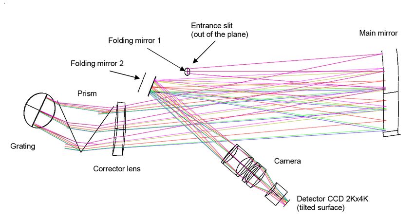
2             J. Vernet et al.: X-shooter, the new wide band intermediate resolution spectrograph at the ESO Very Large Telescope

Table 1. An overview of the hardware and software contributions to X-shooter from the different consortium partners.

                     ESO                                                      PI S. D’Odorico, PM H. Dekker
                                                                              Detector systems
                                                                              Flexure compensation system
                                                                              Cryogenic control electronics
                                                                              Data reduction software
                                                                              Final integration and commissioning
                     Denmark                                                  PI and PM P. Kjaergaard Rasmussen
                     Niels Bohr Institute, Copenhagen University,             UVB & VIS spectrograph (mechanics)
                     DTU Space, Copenhagen                                    Instrument backbone
                                                                              Pre-slit optics and calibration system
                                                                              Instrument control electronics
                     France                                                   PI F. Hammer, PM I. Guinouard
                     Paris Observatory Meudon                                 Integral field unit
                     Astroparticle and Cosmology Paris                        Data reduction software
                     Italy                                                    PI R. Pallavicini/S. Randich, PM F. Zerbi
                     INAF Observatory Palermo,                                UVB & VIS spectrographs (optics)
                     INAF Observatory Brera,                                  Instrument Control Software
                     INAF Observatory Trieste,
                     INAF Observatory Catania
                     The Netherlands                                          PI L. Kaper, PM R. Navarro
                     Netherlands Research School for Astronomy (NOVA)         NIR spectrograph
                     Astronomical Institute, University of Amsterdam          NIR cryostat
                     Astronomical Institute, Radboud University Nijmegen      Data reduction software
                     ASTRON Dwingeloo

a resolution where the instrument is sky limited in a half hour
exposure. Sky background and detector noise considerations re-
quire that the spectral resolution is in the range 5,000 to 7,000
(for a 100 slit). This resolution also ensures that in the near in-
frared, 80 to 90% of the detector pixels are not affected by strong
sky lines so that most of the covered spectrum is sky background
continuum limited. Other constraints on the design of X-shooter
were set by the size and weight (and related flexure) limits of the
VLT Cassegrain focus.
    The X-shooter Science Case (see ESO/STC-324A is broad
and includes various applications ranging from nearby intrinsi-
cally faint stars to bright sources at the edge of the Universe. X-
shooter’s unique wavelength coverage and high efficiency opens
a new observing capacity in observational astronomy. Key sci-
ence cases to be addressed with X-shooter concern the study
of brown dwarfs, young stellar objects and T Tauri stars, the
progenitors of supernovae Type Ia, gamma-ray bursts (GRB),               Fig. 1. A view of X-shooter at the Cassegrain focus below the primary
quasar absorption lines, and lensed high-z galaxies. The advan-          mirror cell of the VLT UT2. In this view from below the instrument
tage of the large wavelength coverage is that e.g. the redshift of       one sees the UVB and VIS spectrographs at the top and bottom, respec-
                                                                         tively. The NIR cryostat is visible in the center. The two boxes on the
the target does not need to be known in advance (as is the case for      left and on the right are electronic cabinets.
GRBs); also, the study of Lyman α in high-redshift galaxies will
be possible in the redshift range 1.5 < z < 15. VLT/X-shooter
will complement and benefit from other major facilities in ob-           2. Instrument design
servational astrophysics operational in the period 2010–2020:
survey instruments like VST/OmegaCAM and VISTA working                   X-shooter consists of a central structure (the backbone) that
in the same wavelength range, and observatories like LOFAR,              supports three prism-cross-dispersed échelle spectrographs opti-
ALMA, JWST, Swift and Fermi exploring other observing win-               mized for the UV-Blue (UVB), Visible (VIS) and Near-IR (NIR)
dows.                                                                    wavelength ranges, respectively. After the telescope focus, a se-
    An overview of the instrument design is given in Sect. 2.            ries of two highly efficient dichroics reflect the UVB and VIS
Performance (resolution, throughput, background, stability) as           light to the corresponding arms and transmit longer wavelengths
measured during testing, commissioning and the first months of           to the NIR arm. A slicer can be inserted in the focal plane, which
science operations is discussed in Sect. 3. In Sect. 4 we summa-         reformats 1.800 ×400 on the sky into a 0.600 ×1200 long slit. A slit
rize the conclusions and provide some suggestions for improve-           unit equipped with 1100 long slits of different widths is located at
ment of the instrument performance. We conclude in Sect. 5 with          the entrance of each spectrograph. A functional diagram of the
an example of a quasar observation obtained during commis-               instrument is given in Fig. 2.
sioning as an illustration of the unique capabilities of the instru-         In this section, we give an overview of the design of X-
ment.                                                                    shooter following photons coming from the telescope. For more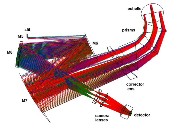
J. Vernet et al.: X-shooter, the new wide band intermediate resolution spectrograph at the ESO Very Large Telescope                    3

                                                                                               instrument shutter
                                              Th-Ar, D2 lamps

                    Calibration unit                                                                   calibration mirrors
                                             Ar Hg Ne Xe lamps
                                             FF lamps

                                A&G
                               camera                                                    acq. pin. mon.          50/50
                                             A&G                                         3 positions mirror      pellicle    IFU   CCD FF
                                        filter wheel                                                                                lamp

                                                                 piezo. 1
                  CCD FF
                   lamp                 exposure VIS slit                        dichro. 1     ADC                                     focus
                                         shutter carriage           ADC                                                        UV
                                                                                                                             spectro
                                                                                       piezo. 2       UV slit exposure
                  focus                                                                              carriage shutter
                                                                                   dichro. 2
                            VIS                                       piezo. 3
                          spectro.
                                                                 COLD                 NIR slit wheel

                                                  NIR spectro.

Fig. 2. Functional diagram of X-shooter. The light path runs from the top to the bottom of the figure. Each element is described in Sect. 2.

detailed discussions of specific aspects and the manufacturing                    cusing of the target on the slit units at the entrance of the respec-
process please refer to the following publications: Spanò et al.                 tive arms.
(2006) for the optical design; Rasmussen et al. (2008) for the                        The size, weight and flexure restrictions implied a very com-
backbone and the UVB and VIS spectrographs; Navarro et al.                        pact optical design of the spectrographs, requiring an efficient
(2006, 2008) for the NIR spectrograph; Roelfsema et al. (2008)                    folding of the light path, especially for the NIR-arm. The solu-
for the cryogenic design; Guinouard et al. (2006) for the Integral                tion was found in selecting the “4C” design described in Delabre
Field Unit; Vidali et al. (2006) for the control software; Goldoni                et al. (1989).
et al. (2006) and Modigliani et al. (2010) for the data reduction                     The inclusion of the K band was the subject of a complex
software.                                                                         trade-off. With its uncooled optics in the pre-slit area the instru-
                                                                                  ment could not be optimized for a low thermal background. On
                                                                                  the other hand the K band did fit well in the spectral format on
2.1. Key design choices                                                           the detector and had a potentially high efficiency. It was finally
                                                                                  decided to include the band, but its inclusion should not reduce
A number of key design choices were made in the phases of                         the performance in the J- and H-bands. It was also decided not
the project definition. Possibly the most crucial design choice                   to cool the instrument pre-slit optics.
was on the method used to split the incoming beam from the                            Another key design choice was the spectral resolution in the
telescope between the three spectral arms. The option to use a                    three arms. The goal was to build an instrument which reaches
single slit in the telescope focal plane was rejected because of                  the dark sky noise limit in about 30 minutes, while still provid-
the difficulty of designing a highly efficient relay system and at-               ing medium resolution to do quantitative work on emission and
mospheric dispersion correction for the full spectral range, and                  absorption lines. In the NIR the resolution of 5600 for 0.900 slit
the need for work-packages with clean interfaces to be handled                    permits the full separation (and subtraction) of the sky emission
by the different consortium partners, which is not possible when                  lines. At UVB and VIS wavelengths, specific scientific programs
spectrographs are sharing a single slit. The solution that was fi-                did call for higher resolving power, e.g. to optimally measure
nally adopted is based on the sequential use of two dichroics                     abundances. The final choices (see Table 4) are obviously a com-
after the focal plane, used at 15◦ rather than 45◦ to minimize                    promise to cover a broad range of astrophysical programs.
polarization effects. The beams toward the UVB and VIS spec-
trographs are then deviated to 90◦ with folding mirrors. These
two folding mirrors together with one in the NIR path are ac-                     2.2. The backbone
tively controlled to compensate for small motions due to flex-
ures in the backbone of the instrument and guarantee that the                     2.2.1. The instrument shutter and the calibration unit
three target images all remain centered on the three slit units as                In the converging beam coming from the telescope, the first ele-
the telescope is tracking (see Sect. 3.5.2).                                      ment is the telescope entrance shutter which allows safe daytime
   The optical design allows the introduction of two short-                       use of X-shooter for tests and calibration without stray-light en-
wavelength atmospheric dispersion correctors (ADC) and the fo-                    tering the system from the telescope side.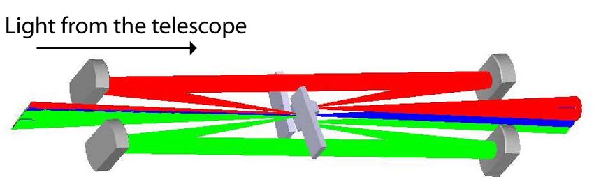
4               J. Vernet et al.: X-shooter, the new wide band intermediate resolution spectrograph at the ESO Very Large Telescope

    This is followed by the calibration unit that allows selection
from a set of flat-fielding and wavelength calibration lamps care-
fully chosen to cover the whole wavelength range (Saitta et al.
2008; Kerber et al. 2008). This unit consists of a mechanical
structure holding calibration lamps, an integrating sphere, relay
optics that simulate the f/13.6 telescope beam, and a mirror slide
with 3 positions that can be inserted in the telescope beam:

    • one free position for a direct feed from the telescope,
    • one mirror that reflects the light from the integrating sphere
      equipped with:
       – wavelength calibration Ar, Hg, Ne and Xe Penray lamps
         operating simultaneously;
       – three flat-field halogen lamps equipped with different
         balancing filters to optimize the spectral energy distri-
         bution for each arm.
    • one mirror which reflects light from:
       – a wavelength calibration hollow cathode Th-Ar lamp;
       – a D2 lamp for flat-fielding the bluest part of the UVB
                                                                            Fig. 3. Top: view of the effect of the IFU. The central field is directly
         spectral range.
                                                                            transmitted to form the central slitlet (blue) while each lateral field (in
                                                                            red and green) is reflected toward a pair of spherical mirrors, and re-
                                                                            aligned at the end of the central slice to form the exit slit. Bottom: The
2.2.2. The acquisition and guiding slide
                                                                            field before (left) and after the IFU (right). The IFU acts such that the
                                                                            lateral fields are rotated. The two white slots are not real gaps but just
Light coming either directly from the telescope or from the cali-
                                                                            guides to help visualize the top and the bottom of each slice in the draw-
bration unit described above arrives at the acquisition and guid-           ing.
ing slide (hereafter A&G slide). This structure allows the inser-
tion into the beam of one of the following components:

    • a flat 45◦ mirror with three positions for:
       – acquisition and imaging (labeled acq. in Fig. 2): the full
           1.50 ×1.50 field of view is sent to the A&G camera. This
           is the position used during all acquisition sequences;
       – spectroscopic observations and monitoring (labeled mon.
           in Fig. 2): a slot lets the central 1000 ×1500 of the field go
           through to the spectrographs while reflecting the periph-
           eral field to the A&G camera. This is the position used
           for all science observations.
       – optical alignment and engineering purposes: a
           0.500 pinhole producing an artificial star (labeled              Fig. 4. The combined efficiency of the two dichroic beam splitters. In
           pin. in Fig. 2) is placed in the focal plane.                    blue: reflection on the first dichroic; in orange: transmission through the
    • the Integral Field Unit (IFU, see Sect. 2.2.3);                       first dichroic and reflection on the second dichroic; in red: transmission
    • a 50/50 pellicle beam splitter at 45◦ used to look down into          through both dichroics.
      the instrument with the A&G camera for engineering pur-
      poses.

                                                                            2.2.4. The acquisition and guiding camera
2.2.3. The IFU
                                                                            The A&G camera allows visual detection and centerering of ob-
The Integral Field Unit is an image slicer that re-images an in-            jects from the U- to the z-band. This unit consists of:
put field of 400 ×1.800 into a pseudo slit of 1200 ×0.600 . The light
from the central slice is directly transmitted to the spectrographs.
The two lateral sliced fields are reflected toward the two pairs             • a filter wheel equipped with a full UBVRI Johnson filter set
of spherical mirrors and re-aligned at both ends of the central                and a full Sloan Digital Sky Survey (SDDS) filter set.
slice in order to form the exit slit as illustrated in Fig. 3. Due to        • a Peltier cooled, 13 µm pixel, 512×512 E2V broad band
these four reflections the throughput of the two lateral fields is             coated Technical CCD57 – 10 onto which the focal plane
reduced with respect to the directly transmitted central one. The              is re-imaged at f/1.91 through a focal reducer. This setup
measured overall efficiency of the two lateral slitlets is 85% of              provides a plate scale of 0.17300 /pix and a field of view of
the direct transmission but drops to 50% below 400 nm due to                   1.470 ×1.470 .
reduced coating efficiency in the blue. Note that each spectro-
graph is equipped with a dedicated 12.600 ×100 opening to be                This acquisition device —that can also be used to record im-
used in combination with the IFU. It is slightly larger than                ages of the target field through different filters— provides a good
the IFU pseudo slit ensuring that the whole field of view is                enough sampling to measure the centroid of a target to better
transmitted while baffling ghosts.                                          than 0.100 accuracy in all seeing conditions.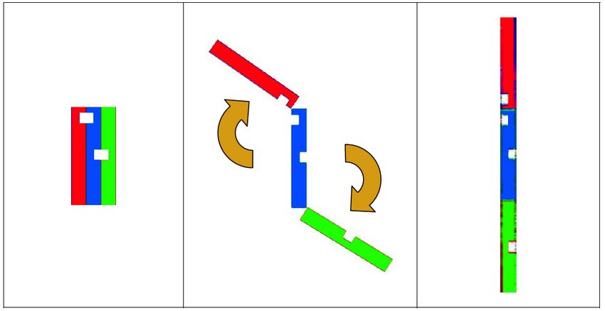
J. Vernet et al.: X-shooter, the new wide band intermediate resolution spectrograph at the ESO Very Large Telescope                  5

2.2.5. The dichroic box

Light is split and distributed to the three arms by two highly effi-
cient dichroic beam splitters. These are the first optical elements
encountered by the science light (unless the IFU is deployed).
The first dichroic at an incidence angle of 15◦ reflects more than
98% of the light between 350 and 543 nm and transmits ∼95%
of the light between 600 and 2300 nm. The second dichroic, also
at 15◦ incidence, has a reflectivity above 98% between 535 nm
and 985 nm and transmits more than 96% of the light between
1045 and 2300 nm. The combined efficiency of the two dichroics
is shown in Fig. 4: it is well above 90% over most of the spectral
range.
                                                                        Fig. 5. The UVB spectrograph optical layout. The optical layout of the
2.2.6. The flexure compensation tip-tilt mirrors                        VIS spectrograph is very similar to this one.

Light reflected and/or transmitted by the two dichroics reaches,
                                                                        2.3. The UVB spectrograph
in each arm, a folding mirror mounted on a piezo tip-tilt mount
(S-340 from Physik Instrumente). These mirrors are used to fold         2.3.1. Slit carriage
the beam and correct for backbone flexure to keep the relative
alignment of the three spectrograph slits fixed at any orientation      The first opto-mechanical element of the spectrograph is the slit
of the telescope and instrument. Operational aspects and per-           carriage. Besides the slit selection mechanism, this unit consists
formance of the flexure compensation system are addressed in            of a field lens placed just in front of the slit to re-image the tele-
Sect. 3.5.2.                                                            scope pupil onto the spectrograph grating, and the spectrograph
                                                                        shutter just after the slit. The slit mask is a laser cut Invar plate
    For slit observations (but not IFU) these tip-tilt mirrors also     manufactured with a LPKF Laser Cutter. It is mounted on a mo-
compensate for shifts due to atmospheric differential refraction        torized slide in order to select one of the 9 positions available.
between the telescope tracking wavelength (fixed at 470 nm) and         All science observation slits are 1100 high and different widths
the undeviated wavelength of the two Atmospheric Dispersion             are available: 0.500 , 0.800 , 1.000 , 1.300 , 1.600 and 500 (the latter for
Correctors (for UVB and VIS arms, see Sect. 2.2.7) and the mid-         spectro-photometric calibration, see Table 4). In addition a sin-
dle of the atmospheric dispersion range for the NIR arm.                gle pinhole for spectral format check and order tracing and a 9-
                                                                        pinhole mask for wavelength calibration and spatial scale map-
                                                                        ping are available. A 12.600 ×100 slit is also available to be used
2.2.7. The focal reducer and atmospheric dispersion                     in combination with the IFU (see Sect. 2.2.3).
       correctors

Both UVB and VIS pre-slit arms contain a focal reducer and an           2.3.2. Optical layout
atmospheric dispersion corrector (ADC). These focal reducer-            The optical layout of the UVB spectrograph is presented in
ADCs consist of two doublets cemented onto two counter rotat-           Fig. 5. Light from the entrance slit, placed behind the plane of
ing double prisms. The focal reducers bring the focal ratio from        the figure, feeds a 5◦ off-axis Maksutov-type collimator through
f/13.41 to f/6.5 and provide a measured plate scale at the en-          a folding mirror. The collimator consists of a spherical mir-
trance slit of the spectrographs of 3.9100 /mm in the UVB and           ror and a diverging fused silica (SiO2 ) corrector lens with only
3.8200 /mm in the VIS. The ADCs compensate for atmospheric              spherical surfaces. The collimated beam passes through a 60◦ sil-
dispersion in order to minimize slit losses and allow orienting         ica prism twice to gain enough cross-dispersion. The main dis-
the slit to any position angle on the sky up to a zenith distance of    persion is achieved through a 180 grooves/mm échelle grating
60◦ . The zero deviation wavelengths are 405 and 633 nm for the         blazed at 41.77◦ . The off-blaze angle is 0.0◦ , while the off-plane
UVB and the VIS ADCs, respectively. During slit observations,           angle is 2.2◦ . After dispersion, the collimator creates an inter-
their positions are updated every 60s based on information taken        mediate spectrum near the entrance slit, where a second folding
from the telescope database.                                            mirror has been placed. This folding mirror acts also as a field
    Since the IFU comes ahead of the ADCs in the optical train,         mirror. Then a dioptric camera (4 lens groups with CaF2 or sil-
no correction for atmospheric dispersion is available for IFU ob-       ica lenses, one aspherical surface) re-images the cross-dispersed
servations, and the ADCs are set to their neutral position in this      spectrum at f/2.7 (plate scale 9.3100 /mm) onto a detector that is
observing mode.                                                         slightly tilted to compensate for a variation of best focus with
                                                                        wavelength. The back focal length is rather sensitive to temper-
    The NIR arm is not equipped with an ADC. The NIR arm                ature changes. It varies by ∼22.7 µm/◦ C which corresponds to
tip-tilt mirror compensates for atmospheric refraction between          a defocus of 9 µm/◦ C or ∼0.0800 /◦ C. This is automatically com-
the telescope tracking wavelength (470 nm) and 1310 nm which            pensated for at the beginning of every exposure by moving the
corresponds to the middle of the atmospheric dispersion range           triplet+doublet of the camera by −10.9 µm/◦ C.
for the NIR arm. This means that this wavelength is kept at the
center of the NIR slit. At a zenith
                                                                        2.3.3. Detector
    distance of 60◦ the length of the spectrum dispersed by the
atmosphere is 0.3500 , so the extremes of the spectrum can be           The UVB detector is a 2048×4102, 15 µm pixel CCD from E2V
displaced with respect to the center of the slit by up to 0.17500 .     (type CCD44-82) of which only a 1800×3000 pixels window is
6 J. Vernet et al.: X-shooter, the new wide band intermediate resolution spectrograph at the ESO Very Large Telescope
used. The CCD cryostat is attached to the camera with the last
optical element acting as a window. The operating temperature
is 153 K. The CCD control system is a standard ESO FIERA
controller (see Beletic et al. 1998) shared with the VIS CCD. The
associated shutter, located just after the slit, is a 25 mm bi-stable
shutter from Uniblitz (type BDS 25). Full transit time is 13 ms.
Since the slit is 2.8 mm high (1100 at f/6.5), the illumination of
the detector is homogeneous to within
10 ms.
2.4. The VIS spectrograph
2.4.1. Slit carriage
The slit carriage of the VIS spectrograph is identical to that of the
UVB arm (see Sect. 2.3.1), but the available slits are different.
All the science observation slits are 1100 high and the slit widths
are: 0.400 , 0.700 , 0.900 , 1.200 , 1.500 and 500 (see Table 4).
2.4.2. Optical layout Fig. 6. The NIR spectrograph optical layout.
The optical layout of the VIS spectrograph is very similar to
that of the UVB (see Fig. 5). The collimator (mirror+corrector
with a roll clicking into the indents. All the science observation
lens) is identical. For cross-dispersion, it uses a 49◦ Schott
slits are 1100 high and different widths are offered: 0.400 , 0.600 ,
SF6 prism in double pass. The main dispersion is achieved
0.900 , 1.200 , 1.500 and 500 (see Table 4). As for the two other
through a 99.4 grooves/mm, 54.0◦ blaze échelle grating. The
arms, a single pinhole, a 9 pinhole mask and an IFU dedi-
off-blaze angle is 0.0◦ and the off-plane angle is 2.0◦ . The
cated 12.600 ×100 slit are available.
camera (three lens groups, one aspherical surface) re-images
the cross-dispersed spectrum at f/2.8 (plate scale 8.9800 /mm)
onto the detector (not tilted). Focussing is obtained by acting 2.5.3. Optical layout
on the triplet+doublet sub-unit of the camera. However, unlike
the UVB arm, the back focal length varies by less than 1 µm/◦ C The optical layout of the NIR spectrograph is presented in Fig. 6.
(image blurJ. Vernet et al.: X-shooter, the new wide band intermediate resolution spectrograph at the ESO Very Large Telescope 7
the-ramp (non-destructive) readout is always used. This means propagated throughout the whole reduction chain (see Horrobin
that during integration, the detector is continuously read out et al. 2008). The most important modules are described below:
without resetting it and counts in each pixel are computed by
fitting the slope of the signal vs. time. In addition, Threshold – xsh mbias and xsh mdark combine series of raw biases and
Limited Integration (TLI) mode is used to extend the dynamical darks into a master bias and a master dark respectively. These
range for long exposure times: if steps also update a reference master bad pixel map.
one pixel is illuminated by a bright source and reaches an – xsh predict takes as input a single pinhole arc calibration
absolute value above a certain threshold (close to detector sat- frame (named format check, see left hand panel on Fig 7)
uration), only detector readouts before the threshold is reached and computes a first guess for the wavelength solution and
are used to compute the slope and the counts written in the FITS position of the center of each order taking into account infor-
image for this pixel are extrapolated to the entire exposure time mation on atmospheric pressure and instrument temperature
(see Finger et al. 2008). available in the FITS header.
To significantly decrease persistence, a global reset is applied – xsh orderpos takes as input a continuum lamp illuminated
immediately after finishing science exposures and pixels of the single pinhole calibration frame (named order definition
array are kept at the reset voltage until the next exposure starts. frame, see central panel on Fig 7) and accurately traces the
The release of trapped charge during a dark exposure immedi- center of each order.
ately following an exposure to a bright light source is the cause – xsh mflat combines a series of raw flat field frames into a
of the persistence effect. If all pixels of the array are connected master flat field. It also traces the edge of each orders. In
to the reset voltage the diode junctions and the width of their case of IFU calibrations, it traces the edge of each slitlet.
depletion regions do not change even if the array is exposed to – xsh 2dmap takes as input a 9-pinhole mask arc frame (see
a bright light source with photons generating charge. Hence, no an example on Fig 7, right hand panel) together with a first
traps in the depletion region are exposed to majority carriers. On guess wavelength solution derived by the preceding recipes
the contrary, trapped charge is released during the global reset and determines the wavelength and spatial scale calibra-
before the next exposure starts. By two minutes of global reset tion. Two calibration methods are proposed: either a classical
de-trapping (typical time interval in between two science expo- method based on two dimensional polynomial fitting of the
sures in a nodding sequence) the persistence effect can be re- detected arc lines or a method based on the optimization of
duced by a factor of ten. If the reset switch is kept closed during a physical model of the instrument (see Bristow et al. 2008).
the bright exposure prior to the dark exposures the persistence – xsh flexcomp updates the wavelength solution to correct for
is eliminated and the global reset acts like an electronic shutter the effect of flexures and temperature drifts using the first
protecting the detector from exposure to bright sources. frame of the active flexure compensation sequence taken dur-
ing each pointing (see Sect. 3.5.2).
2.6. The Instrument Control and Observing Software – xsh response takes as input observations of a spectro-
photometric standard star and computes the response func-
The X-Shooter control software is based on the standard ESO tion.
VLT control software (see Raffi & Wirenstrand 1997). The num- – xsh scired slit stare, xsh scired slit nod and
ber of functions to control is relatively low compared to other xsh scired slit onoff recipes process science data for
large VLT instruments (8 calibration lamps; 13 motors; 3 tip- the three main observing strategies used in slit mode: star-
tilt piezoelectric actuators; 55 digital and analog sensors and 4 ing, nodding along the slit and sampling of the sky off target,
detectors, see Fig. 2). The two most critical aspects are: the syn- respectively. These recipes first subtract the bias (UVB
chronization of exposures between the three arms and the real and VIS) or the master dark (NIR) and divide by a master
time flexure compensation, see Sect. 3.5.2. flat-field. When less than three science frames per pointing
are given as input, cosmic ray rejection using laplacien
edge detection method described in van Dokkum (2001) is
2.7. Data reduction software applied to each frame, otherwise frames are combined with
Delivery of the X-shooter data reduction pipeline1 (Goldoni a Kappa-Sigma clipping. In the staring case, the sky back-
et al. 2006; Modigliani et al. 2010) was an important part of ground is fitted and subtracted taking advantage of the fine
the X-shooter project. It provides recipes for Paranal Science sampling naturally provided by distortions of the spectral
Operations, for data Quality Control at ESO headquarters and format following prescriptions detailed in Kelson (2003). In
for offline data reduction by science users. While it is used in a case of nodding along the slit, the so-called double pass sky
fully automated mode for quick-look data evaluation on Paranal, subtraction is applied (first pass: subtraction of frames from
the pipeline is fully configurable through an extended set of pa- the second position from those of the first one to produce a
rameters to allow astronomers to tune the reduction to their spe- difference frame; second pass: co-addition of the difference
cific needs. Pipeline recipes can be executed either with the ESO frame with a negative and shifted version of itself to co-add
Recipe Execution Tool (EsoRex2 ) at the command line level or signal from the two positions and remove residuals due to
through the Gasgano3 graphical user interface. The recipes are variations in the sky background). These recipes produce,
implemented with the ESO Common Pipeline Library (CPL, for each arm, a two-dimensional rectified spectrum that is
Banse et al. 2004; McKay et al. 2004). wavelength, spatial scale and flux calibrated. It is possible
The data reduction pipeline is built up in modules which in to automatically detect objects and extract one-dimensional
combination lead to fully reduced spectra but permit the extrac- spectra with either a simple sum over an aperture or an
tion of intermediate results when required by the user. Errors are optimal extraction.
– xsh scired ifu stare and xsh scired ifu onoff process IFU
1
available at http://www.eso.org/sci/software/pipelines/ data and reconstruct calibrated data cubes for each arm.
2
available at http://www.eso.org/sci/software/cpl/esorex.html These recipes are similar to their slit mode equivalents de-
3
available at http://www.eso.org/sci/software/gasgano/ scribed above. The flat-fielding step corrects for the differ-8 J. Vernet et al.: X-shooter, the new wide band intermediate resolution spectrograph at the ESO Very Large Telescope
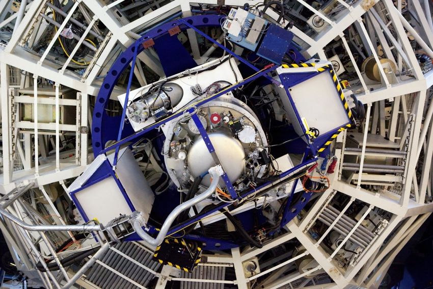
Fig. 7. Sections (1365 pix × 925 pix) of VIS arm calibration frames used by the data reduction pipeline to fully characterize the spectral format.
From left to right: a single pinhole arc frame (“format check”), a single pinhole continuum frame (”order definition”) and a 9-pinhole arc frame
used for spatial scale and wavelength calibration.
ence in throughput between the two lateral sub-fields and the 3.4. Efficiency
central one (see Section 2.2.3). Note that due to the small
field of view of the IFU, nodding within the IFU is not a rec- Thanks to the very high efficiency of the two dichroics split-
ommended observing strategy and thus is not supported by ting light between the three arms (see Fig. 4) and the careful
the pipeline. optimization of each arm, the resulting overall throughput of X-
shooter is very high. The efficiency for each order as measured
during the last commissioning run using spectro-photometric
standard BD+17 4708 is given in Fig. 8. Taking orders individ-
3. X-shooter performance ually (i.e. not combining signal from adjacent orders), the total
efficiency (including telescope and detectors) peaks at 33%, 34%
3.1. Detectors and 31% for the UVB, VIS and NIR arm, respectively.
The overall efficiency is essentially as predicted by multi-
The performance of the detectors of each arm are given in
plying efficiencies of the different optical elements and detectors
Table 2 for all readout modes offered for science observations
except for the J band where it is ∼30% below our predictions,
and calibrations.
due to losses that can only be partly explained by scattering in
the ZnSe cross-disperser prisms.
3.2. Spectral format
3.5. Stability
The spectral format of X-shooter is fixed. The whole spectral
range is covered by 12 orders in the UVB, 15 in the VIS, and 16 Being mounted at the Cassegrain focus, X-shooter is subject to a
in the NIR. Orders are strongly curved (parabolic) and the spec- changing gravity vector, hence instrument flexure has to be kept
tral line tilt varies along the orders. Both slit height and width under control.
projection also vary from order to order and along each order This splits into two components: (i) flexure within each spec-
due to a variable anamorphic effect introduced by the prisms trograph (i.e. after the slit) that mainly affects the quality of the
(crossed twice). The minimum separation between orders is ∼4 wavelength calibration and the sky subtraction (see Sect. 3.5.1);
(unbinned) pixels to allow inter-order background evaluation. (ii) flexure of the instrument backbone (i.e. before the slit) that
The dichroic crossover between UVB-VIS and VIS-NIR is at affects the relative alignment of the three spectrographs (see
559.5 nm and 1024 nm respectively, near the location of atmo- Sect. 3.5.2).
spheric features. Grating line densities were chosen to have the
crossovers occur near the ends of the order. The spectral ranges
on the detector and blaze wavelength for each order are given in 3.5.1. Spectrograph flexures
Table 3 together with an example of a Th-Ar slit frame for each Changes in the spectral format with position have been analyzed
arm. These measurements are in excellent agreement with the in detail during integration and testing in Garching and further
predicted spectral format (Spanò et al. 2006). checked during commissioning in Paranal. Performance at the
telescope is shown in Fig. 9.
3.3. image quality and spectral resolution
For the UVB and the VIS arm, the image motion measured
throughout the whole detector using many calibration lines is
In terms of image quality, spectral resolution and sampling, the identical, meaning that flexure induces a simple rigid shift of the
three arms of X-shooter perform fully within specifications4 . spectral format. The amplitude of this displacement with respect
Resolution and sampling as a function of slit width are given to the position at zenith for a full rotation of the instrument at a
in Table 4. zenith distance of 60◦ is .1.15 pixels in the UVB arm and . 1.0
pixel in the VIS arm as shown in panel (a) and (b) of Fig. 9. No
4 variation of image quality is measured for those two arms.
The original specifications for the resolution (R=λ/∆λ) with a
100 slit were: R>5000 for the UVB arm, R>7500 for the VIS arm and Concerning the NIR arm, the flexure behavior is more com-
R> 4800 for the NIR arm with a sampling of the line spread function plex as illustrated in panel (c) of Fig. 9 which shows with dif-
>5 pixels. For a 0.600 slit, the specifications were: R>7600 for the UVB ferent colors the recorded image motion for various calibration
arm, R>11500 for the VIS arm and R> 7000 for the NIR arm with a lines throughout the spectral format. Relative to their (x, y) posi-
sampling of the line spread function >3 pixels. tion at zenith, spectral lines move by up to 1.4 pixels. However,J. Vernet et al.: X-shooter, the new wide band intermediate resolution spectrograph at the ESO Very Large Telescope 9
Table 2. Detector performances.
Chanel UVB VIS NIR
Detector type e2v CCD44-82 MIT/LL CCID 20 Hawaii 2RG
(substrate removed)
QE 80% at 320 nm 78% at 550nm 85%
88% at 400 nm 91% at 700nm
83% at 500 nm 74% at 900nm
81% at 540 nm 23% at 1000nm
Gain High: 0.62 High 0.595 2.12
(e− /ADU) Low: 1.75 Low: 1.4
Readout noise Slow: 2.5 Slow 3.1 Short DIT: ∼25
(e− rms) Fast: 4.5 Fast: 5.2 DIT>300s:∼8
Full frame 1×1, slow-fast: 70-19 1×1, slow-fast: 92-24 0.665 (for a
readout time 1×2, slow-fast: 38-12 1×2, slow-fast: 48-14 single readout)
(s) 2×2, slow-fast: 22-8 2×2, slow-fast: 27-9
Dark current < 0.210 J. Vernet et al.: X-shooter, the new wide band intermediate resolution spectrograph at the ESO Very Large Telescope
Table 3. The X-shooter spectral format for the UVB (top), VIS (middle) and NIR (bottom) arm as measured at the telescope. The minimum and
maximum wavelength recorded on the detector together with the blaze wavelength are given for each order ; on the right column, an example of
wavelength calibration frame taken with a ThAr lamp for each arm.
Order min. wavelength Blaze wavelength Max. wavelength Example of a ThAr
(nm) (nm) (nm) calibration frame
UVB
24 293.6 312.2 322.3
23 306.2 325.0 336.2
22 320.0 339.8 351.4
21 335.1 356.1 368.0
20 351.8 373.5 386.2
19 370.1 393.2 406.4
18 390.6 414.5 428.9
17 413.4 438.8 454.0
16 439.1 466.4 482.2
15 468.3 496.8 514.2
14 501.6 531.0 550.8
13 540.1 556.0 593.0
VIS
30 525.3 550.5 561.0
29 535.8 568.0 580.2
28 554.6 585.9 600.8
27 575.2 607.7 622.9
26 597.4 629.5 646.8
25 621.3 653.8 672.5
24 647.2 682.1 700.4
23 675.4 711.2 730.7
22 706.1 742.6 763.8
21 739.7 777.6 800.0
20 777.0 815.8 839.8
19 817.6 860.2 883.8
18 862.9 904.3 932.7
17 913.7 957.3 987.4
16 970.7 1001.6 1048.9
NIR
26 982.7 1005.8 1034.2
25 1020.5 1046.0 1076.7
24 1062.0 1089.6 1122.9
23 1106.6 1137.0 1173.1
22 1155.2 1188.6 1228.0
21 1208.2 1245.2 1288.5
20 1266.5 1307.5 1355.2
19 1330.3 1376.3 1429.4
18 1400.8 1452.8 1511.5
17 1479.5 1538.2 1604.0
16 1567.1 1634.4 1708.7
15 1667.8 1743.3 1823.3
14 1785.7 1867.9 1952.8
13 1922.6 2011.5 2102.0
12 2082.9 2179.3 2275.6
11 2272.3 2377.28 2480.7
2. take a spectrum using a reference 0.500 pinhole in the that is used by the data reduction pipeline to correct the wave-
cassegrain focal plane (see Fig. 10b); length solution for for thermally- and gravity-induced drifts (see
3. measure the displacement between the two frames (at the un- Modigliani et al. 2010).
deviated wavelength of the atmospheric dispersion compen-
sator) using a cross-correlation algorithm;
4. send corresponding commands to piezos (Fig. 10c); 3.6. Near-IR arm background
5. repeat steps 2 & 3 to check convergence.
The near-infrared sky is very dark in between the OH sky emis-
This whole procedure comes at no expenses in terms of over- sion lines (Maihara et al. 1993). In order to reach sky background
heads since it is done in parallel with the telescope active op- limited conditions, keeping the instrument background at the
tics setup. It is operationally very robust and does not require lowest possible level is therefore of utmost importance. Though
any user interaction. Our measurements show that it reliably a critical aspect of the performance of any near-IR spectrograph,
maintains the alignment of the three slits to better than 0.0200 , it is however quite challenging and requires rigorous design and
as illustrated in Fig. 11. As a side product, the first frame of careful manufacturing (eg. good baffling, limited number of ca-
the sequence is actually an “attached” wavelength calibration ble feed-throughs).J. Vernet et al.: X-shooter, the new wide band intermediate resolution spectrograph at the ESO Very Large Telescope 11
Table 4. Measured resolution and sampling as a function of slit width.
UVB VIS NIR
Slit width Resolution Sampling Slit width Resolution Sampling Slit width Resolution Sampling
(00 ) (λ/δλ) (pix/FWHM) (00 ) (λ/δλ) (pix/FWHM) (00 ) (λ/δλ) (pix/FWHM)
0.5 9100 3.5 0.4 17400 3.0 0.4 11300 2.0
0.8 6300 5.2 0.7 11000 4.8 0.6 8100 2.8
1.0 5100 6.3 0.9 8800 6.0 0.9 5600 4.0
1.3 4000 8.1 1.2 6700 7.9 1.2 4300 5.3
1.6 3300 9.9 1.5 5400 9.7 1.5 3500 6.6
IFU 7900 4.1 IFU 12600 4.2 IFU 8100 2.8
instrument shutter instrument shutter
Th-Ar, D2 lamps Th-Ar, D2 lamps
Calibration unit calibration mirror in: Penray lamps ON Calibration unit calibration mirrors in: Penray lamps ON
Ar KrNeXe lamps Ar KrNeXe lamps
FF lamps FF lamps
A&G A&G
camera 50/50
camera 50/50
3 positions mirror 3 positions mirror
A&G monitoring in pellicle IFU CCD FF A&G 0.5” pinhole in pellicle IFU CCD FF
filter wheel lamp filter wheel lamp
piezo. 1 piezo. 1
CCD FF CCD FF
lamp exposure 0.5” pinhole dichro. 1 ADC focus lamp exposure 5” wide slit dichro. 1 ADC focus
shutter in ADC UV shutter in ADC UV
spectro spectro
piezo. 2 0.5” pinhole exposure piezo. 2 5” wide slit exposure
focus in shutter focus in shutter
dichro. 2 dichro. 2
VIS piezo. 3
VIS piezo. 3
spectro. spectro.
COLD 0.5” pinhole in COLD 5” wide slit in
NIR spectro. NIR spectro.
(a) AFC step 1 (b) AFC step 2
instrument shutter
Th-Ar, D2 lamps
Calibration unit calibration mirrors
Ar KrNeXe lamps
FF lamps
A&G
camera acq. pin. mon. 50/50
A&G 3 positions mirror pellicle IFU CCD FF
filter wheel lamp
move piezo. 1
CCD FF
lamp exposure VIS slit dichro. 1 ADC focus
shutter carriage ADC UV
spectro
move UV slit exposure
piezo. 2 carriage shutter
focus dichro. 2
VIS move piezo. 3
spectro.
COLD NIR slit wheel
NIR spectro.
(c) AFC step 3
Fig. 10. The three steps of the flexure compensation procedure. For each step, functions that are moved are highlighted in red. In step 1, panel (a),
the ArHgNeXe calibration lamps are switched on, the 3-position mirror in the A&G slide is set to the wide slot position and the 0.500 pinhole is
inserted in the slit unit of each spectrograph ; in step 2, panel (b), the calibration lamp is still on, the 3-position mirror is set to the 0.500 pinhole
position and the wide 500 slit is inserted in each slit unit ; in step 3, panel (c), the piezo mounted folding mirrors are moved according to the
measurements obtained in step 1 and 2.
The near-IR arm of X-shooter is a remarkably dark instru- ground would be around 4 e− i.e. less than the read noise of the
ment: with a closed slit the measured background is below 0.01 detector.
e− /s/pix. This means that assuming a sky background level as
However, on sky measurements have revealed a background
measured by Maihara et al. (1993), the instrument background
level estimated from the intensity of the inter-order space in
should be a factor two to three below the sky. In addition, in an
the J- and the H-band a factor of three to five higher than the
exposure of 1800s, the photon noise from the instrument back-
sky level. This stray light flux level rises in proportion to the
slit width. A complete analysis of the background level using12 J. Vernet et al.: X-shooter, the new wide band intermediate resolution spectrograph at the ESO Very Large Telescope
X−shooter UVB efficiency
0.5
Measured Extinction Corrected UVB slit alignment wrt A&G reference PH
Measured Not Corrected
Offset wrt ref. PH perp. to slit ["]
0.4 Without AFC
0.05 With AFC
0.3
Efficiency
0.00
0.2
0.1 −0.05
0.0 −0.2 −0.1 0.0 0.1 0.2
300 350 400 450 500 550 Offset wrt ref. PH along slit ["]
Wavelength [nm]
X−shooter VIS efficiency
0.5
Measured Extinction Corrected
Measured Not Corrected Fig. 11. Alignment of the UVB arm 0.500 pinhole with respect to the fo-
0.4 cal plane reference pinhole with (red) and without the flexure compen-
sation (black) through a full rotation of X-shooter at a zenith distance of
0.3 60◦ . The AFC allows to maintain the alignment to ∼0.0100 , well within
Efficiency
specification of 1/10th of the narrowest slit width.
0.2
0.1
reasonable range ensuring no significant impact on science per-
0.0
formance. The novel concept developed to compensate for back-
600 700 800 900 1000 bone flexures and accurately maintain the three slits staring at the
Wavelength [nm] same patch of sky is very efficient and robust in operations.
X−shooter NIR efficiency
After two “science verification” runs5 in August and
0.5 September 2009, the instrument started regular operation in pe-
riod 84, that is on October 1st , 2009. In the first four Calls for
0.4 Proposals for the VLT in which X-shooter has been offered (ESO
Period 84 to 87), it has been the second most requested of the 14
0.3 available instruments, with a ratio requested versus scheduled
Efficiency
observing time of 3.2. The first year of operations confirms the
0.2 high versatility of the instrument and the very broad range of
topics tackled by X-shooter, as anticipated in the original sci-
0.1
ence case analysis, from stellar astrophysics (see e.g. Bragaglia
et al. 2010; Schwope & Christensen 2010; Rigliaco et al. 2011;
0.0
1000 1200 1400 1600 1800 2000 2200 2400 Kaper et al. 2011), cosmic explosions (e.g. de Ugarte Postigo
Wavelength [nm] et al. 2010; D’Elia et al. 2010) to the high redshift Universe (e.g.
Dessauges-Zavadsky et al. 2010; Fynbo et al. 2010; Christensen
et al. 2010).
Fig. 8. The overall throughput of X-shooter, including telescope, as
measured during the last commissioning run in september 2009 using Several ideas to further improve the performance of X-
spectro-photometric standard BD+17 4708. Blue curves represent raw shooter or add new functionalities have been proposed. The most
measurements and black curves show the efficiency corrected for atmo- advanced one concerns the reduction of the J- and H-band back-
spheric extinction (UVB and VIS only). ground. As explained in Sect. 3.6, due to scattered light from the
very bright thermal background dominated K-band orders, sky
limited observations in the J- and H-band are currently not pos-
all commissioning data spaning a range of observing conditions sible. There was a choice of either simply baffling the longest
further showed that this spurious background is correlated with wavelength orders or placing a cold filter in front of some of the
ambient temperature as shown in Fig. 13. This indicates that it slits. The second option was chosen and two new slits (0.600 and
is probably caused by K band radiation that is reflected by the 0.900 wide) equipped with a short pass filter blocking the spec-
detector into the camera and then comes back to the detector as tral range above 2µm will be fitted into the NIR spectrograph
a diffuse stray light background. slit wheel. Blocking the K-band radiation should restore the ex-
The immediate consequence is that in the J and H-band the pected low background at the expense of the spectral range for
instrument in its present state is clearly not sky background lim- those two new slits. In order to allow the acquisition of faint
ited. red sources — critical in the case of some GRB observations
for instance —, the feasibility of adding a near-IR channel to
4. Overview and future upgrades the acquisition system is being investigated. In addition, the
possibility to add spectro-polarimetric capabilities and the idea
In this paper, we have presented key figures demonstrating X- of replacing the piezo mounts of the folding mirrors to allow
shooter’s high performance on sky. This unique instrument lives (counter)nodding in the UVB and VIS arms (i.e. nodding along
up to expectations in terms of high throughput, resolution and
exquisite image quality. It is overall a bit less stable than orig- 5
All science verification proposals and data are publicly available at
inally targeted but flexures are nevertheless kept within a very http://www.eso.org/sci/activities/vltsv/xshootersv.htmlJ. Vernet et al.: X-shooter, the new wide band intermediate resolution spectrograph at the ESO Very Large Telescope 13
Fig. 13. Background level measured in the inter-order background re-
gion on both sides of order 21 at 1238.64 nm versus ambient tempera-
ture.
were obtained during the commissioning of the instrument in
its full configuration in March 2009 to secure a template spec-
trum of a QSO over the full spectral range. The spectrum cov-
ers the wavelength interval 70-520 nm in the rest frame of the
QSO. The integration time was 4800s split over 4×1200s expo-
sures. The brightest two of the lensed QSO images, separated
by 0.500 , were aligned along the slit and the extracted spectrum
refers to the sum of the two. The reduction was carried out with
the standard X-shooter data reduction package. The final signal-
to-noise ratio is between 50 and 100 over most of the spectrum.
The spectral resolution is 6,200, 11,000 and 8,100 in the UVB,
VIS and NIR spectral instrument arms respectively (on average
two pixel sampling of the resolution element). The wavelength
scale is calibrated to an accuracy of better than 2 km/s in the VIS
arm and better than 4 km/s in the UVB and NIR arms, as verified
on sky emission lines. The spectrum shown in Fig. 14 has been
corrected for relative spectral response of the instrument via a
standard star to a 5% accuracy. Since the night was not photo-
metric, an accurate absolute flux scale could not be established.
The quality of the X-shooter spectra can be also judged from
a comparison with the best high resolution data of this QSO in
Fig. 12. Stability of the UVB (top), VIS (center) and NIR (bottom) the literature. Songaila & Cowie (1996) discuss the metal ab-
spectrographs over 6 consecutive nights as measured during the third sorption systems in the line of sight to this QSO from Keck
commissioning run. The dark and light green points show the FWHM HIRES spectra at resolution 36000 (total exposure time 8.3 hrs).
in X and Y of a 0.500 pinhole, the black and blue points show the X and Fig. 15 shows two C IV metal systems for which the correspond-
Y position of a reference calibration line with respect to its position ing Lyα and Lyβ are also observed in the same exposure. A com-
measured at zenith on the first day and the red points show the ambi- parison with the corresponding tracings in Fig. 2 of Songaila &
ent temperature (for UVB and VIS only since it is irrelevant for the Cowie (1996) shows that all the components of the metal sys-
temperature controlled NIR arm).
tems are detected although the resolution of the X-shooter is
nominally a factor of 3 lower and the exposure time a factor of 4
the slit in the NIR arm while keeping the target at the same po- shorter.
sition in the UVB and VIS arm) have also been proposed. This is the first time that a QSO is observed over such a wide
spectral range in a single observation. With a standard optical
or infrared spectrograph only limited regions of the spectrum
5. The spectrum of the QSO B1422+231. could be studied with a single exposure, with the potential risk
of introducing errors in the final compilation of data taken at
Finally, as an example of the observing capability of the instru-
different times and under different weather conditions. With X-
ment, we show in Fig. 14 the reduced X-shooter spectrum of
shooter data it is now possible to circumvent these obstacles.
B1422+231 (z =3.62). This QSO is sufficiently bright (V ∼ 16.5
mag) due to gravitational lensing to be observed at medium-high Acknowledgements. The X-shooter project acknowledges financial support
resolution with high signal-to-noise in about 1 hour. These data from the EU Descartes prize 2002 ”Solving the gamma-ray burst riddle: the uni-14 J. Vernet et al.: X-shooter, the new wide band intermediate resolution spectrograph at the ESO Very Large Telescope
Fig. 14. Spectrum of the lensed QSO B1422+231. The blue part of the spectrum shows the UVB, the green the VIS, and the red the NIR data. No
correction for telluric lines has been applied.
verse’s biggest explosions” (PI Ed van den Heuvel), the Carlsberg foundation, Guinouard, I., Horville, D., Puech, M., et al. 2006, in SPIE Conference Series,
the Netherlands Research School for Astronomy NOVA, and the Netherlands ed. E. Atad-Ettedgui, J. Antebi, & D. Lemke, Vol. 6273, 62733R
Organization for Scientific Research NWO. The design and implementation of Horrobin, M., Goldoni, P., Royer, F., et al. 2008, in 2007 ESO Instrument
the control software of X-Shooter was carried out in the framework of a PRIN Calibration Workshop, ed. A. Kaufer & F. Kerber, 221–223
project of the MIUR (Italian Ministry of Education, University and Research). Kaper, L., Ellerbroek, L. E., Ochsendorf, B. B., & Caballero Pouroutidou, R. N.
We thank J. Prochaska for discussions on the optimal approach to the data re- 2011, Astronomische Nachrichten, 332, 232
duction in the early phases of the project. Kelson, D. 2003, PASP, 115, 688
Kerber, F., Saitta, F., Bristow, P., & Vernet, J. 2008, SPIE Conference Series,
7014
References Maihara, T., Iwamuro, F., Yamashita, T., et al. 1993, PASP, 105, 940
McKay, D. J., Ballester, P., Banse, K., et al. 2004, SPIE Conference Series, 5493,
Banse, K., Ballester, P., Izzo, C., et al. 2004, in Astronomical Society of the 444
Pacific Conference Series, Vol. 314, Astronomical Data Analysis Software Meyer, M., Finger, G., Mehrgan, H., Nicolini, G., & Stegmeier, J. 1998, in SPIE
and Systems (ADASS) XIII, ed. F. Ochsenbein, M. G. Allen, & D. Egret, Conference Series, ed. A. M. Fowler, Vol. 3354, 134–138
392 Modigliani, A., Goldoni, P., Royer, F., et al. 2010, SPIE conference series
Beletic, J. W., Gerdes, R., & Duvarney, R. C. 1998, in Astrophysics and Space Navarro, R., Elswijk, E., de Haan, M., et al. 2006, SPIE Conference Series, 6273
Science Library, Vol. 228, Optical Detectors for Astronomy, ed. J. Beletic & Navarro, R., Elswijk, E., Tromp, N., et al. 2008, SPIE Conference Series, 7014,
P. Amico, 103 70141Y
Bragaglia, A., Carretta, E., Gratton, R. G., et al. 2010, ApJ, 720, L41 Raffi, G. & Wirenstrand, K. 1997, in SPIE Conference Series, ed. A. L. Ardeberg,
Bristow, P., Kerber, F., Rosa, M. R., et al. 2008, SPIE Conference Series, 7014 Vol. 2871, 996–1004
Christensen, L., D’Odorico, S., Pettini, M., et al. 2010, MNRAS, 406, 2616 Rasmussen, P. K., Zerbi, F. M., Dekker, H., et al. 2008, SPIE Conference Series,
de Ugarte Postigo, A., Goldoni, P., Thöne, C. C., et al. 2010, A&A, 513, A42+ 7014
Delabre, B., Dekker, H., D’Odorico, S., & Merkle, F. 1989, SPIE Conference Rigliaco, E., Natta, A., Randich, S., et al. 2011, A&A, 526, L6+
Series, 1055, 340 Roelfsema, R., Albers, P., Lizon, J., et al. 2008, SPIE Conference Series, 7017
D’Elia, V., Fynbo, J. P. U., Covino, S., et al. 2010, A&A, 523, A36+ Saitta, F., Kerber, F., Bristow, P., et al. 2008, in 2007 ESO Instrument Calibration
Dessauges-Zavadsky, M., D’Odorico, S., Schaerer, D., et al. 2010, A&A, 510, Workshop, ed. A. Kaufer & F. Kerber, 57–61
A26+ Schwope, A. D. & Christensen, L. 2010, A&A, 514, A89+
D’Odorico, S., Andersen, M. I., Conconi, P., et al. 2004, SPIE Conference Series, Songaila, A. & Cowie, L. L. 1996, AJ, 112, 335
5492, 220 Spanò, P., Delabre, B., Norup Sørensen, A., et al. 2006, SPIE Conference Series,
D’Odorico, S., Dekker, H., Mazzoleni, R., et al. 2006, SPIE Conference Series, 6269
6269 van Dokkum, P. G. 2001, PASP, 113, 1420
Finger, G., Dorn, R. J., Eschbaumer, S., et al. 2008, SPIE Conference Series, Vernet, J., D’Odorico, S., Christensen, L., et al. 2009, The Messenger, 138, 4
7021, 70210P Vidali, M., Di Marcantonio, P., Santin, P., Vernet, J., & Zacchei, A. 2006, SPIE
Fynbo, J. P. U., Laursen, P., Ledoux, C., et al. 2010, MNRAS, 408, 2128
Goldoni, P., Royer, F., François, P., et al. 2006, SPIE Conference Series, 6269You can also read