BACHELOR'S THESIS Improving the efficiency of Deepsea Aberdeen's central cooling system - HVL Open
←
→
Page content transcription
If your browser does not render page correctly, please read the page content below
BACHELOR’S THESIS

Improving the efficiency of Deepsea
Aberdeen’s central cooling system

Even Sælen Uthaug
Kjell Martin Dagsvik
Patrick Desmond McCann
Sindre Eide Steffensen

Automation
Department of Computer science, Electrical engineering
and Mathematical sciences
28/05/2021
BO21E-20 Improving the efficiency of Deepsea Aberdeen's freshwater cooling system

Document Control

Report title BO21-20 Date/Version
Improving the efficiency of Deepsea Aberdeen’s central cooling system 31. May. 2021/1.3
 Report number:
 B021E-20
Author(s): Course:
Even Sælen Uthaug ELE150
Kjell Martin Dagsvik Number of pages including
 appendixes
Patrick Desmond McCann
Sindre Eide Steffensen 58

Supervisor at Western Norway University of Applied Sciences Security classification:
Svein Haustveit Open
Comments:
We, the authors, allow publishing of the report.

Contracting entity: Contracting entity’s reference:
Name of company or institution (Number or ID if any)
Contact(s) at contracting entity, including contact information:
Odfjell Drilling, Thomas Borsholm

Revision Date Status Performed by
0.1 29/01/2021 Draft Issued to Odfjell Drilling HVL Students
1.0 29/01/2021 Issued for Validation HVL Students
1.1 20/05/2021 Issued rough draft HVL Students
1.2 25/05/2021 Issued draft HVL Students
1.3 28/05/2021 Issued paper HVL Students
BO21E-20 Improving the efficiency of Deepsea Aberdeen's freshwater cooling system

Preface
This bachelor thesis is written as a solution for Odfjell Drilling’s cooling system, and as the final
assignment for our bachelor’s degree in Automation engineering at Western University of Applied
Sciences (HVL).

We would like to thank everyone involved in this project at Odfjell Drilling, both from our visit to the
platform back in December 2020 and from meetings and discussions throughout the year. We would
especially like to thank Thomas Borsholm for the constant help and support he has provided while
working on our thesis. We would also like to thank our internal supervisor at HVL, Svein Haustveit, for
guiding us in the right directions. Lastly, we would like to thank Lars Manger Ekroll from HVL for
providing us equipment that has proved to be invaluable for developing and testing our software.

Rev: 1.3 Page 3 of 58 31.05.2021
BO21E-20 Improving the efficiency of Deepsea Aberdeen's freshwater cooling system

Summary
In this project our job was to explore the possibility of optimizing the central cooling system on one of
Odfjell Drilling’s Semi-submersible drilling units. The project involved developing a solution to optimize
the operation of the central cooling system and determining the saving potential of the solution. The
scope of the project was initially to evaluate the freshwater part of the cooling system. We later
expanded the scope to also include the seawater system as there was an even greater savings
potential.

The recommended solution we will discuss in our thesis is to implement variable frequency drives
(VFD) to the seawater and freshwater pump. The seawater cooling pumps will run at variable speed
based on the demand for cooling in the freshwater system. The freshwater cooling pumps will be able
to run at constant pressure meaning that the system will actively control itself to only deliver the
needed flow. In addition to the VFD’s on the freshwater cooling system, we will also recommend
mounting pneumatic actuators on several consumers of the freshwater cooling system. This will
reduce unnecessary use of cooling water and reduce the overall flow of the system.

Rev: 1.3 Page 4 of 58 31.05.2021
BO21E-20 Improving the efficiency of Deepsea Aberdeen's freshwater cooling system

 Table of Contents
Document Control .................................................................................................................................... 2
Preface...................................................................................................................................................... 3
Summary .................................................................................................................................................. 4
1 Introduction.................................................................................................................................... 10
 1.1 Contracting entity .................................................................................................................. 10
 1.2 Problem description ............................................................................................................... 11
 1.3 Cooling System Description.................................................................................................... 11
 1.4 Current energy usage ............................................................................................................. 12
 1.5 Specification of requirements ................................................................................................ 13
 1.6 Redundancy philosophy ......................................................................................................... 13
2 Main Solutions Ideas ...................................................................................................................... 14
 2.1 General Information ............................................................................................................... 14
 2.2 VFD implementation on the freshwater system .................................................................... 15
 2.3 Implementation of automated valves.................................................................................... 16
 2.4 VFD implementation on the seawater system....................................................................... 16
3 Freshwater and Seawater VFD Solutions ....................................................................................... 18
 3.1 General Solution ..................................................................................................................... 18
 3.2 Freshwater VFD ...................................................................................................................... 25
 3.3 Seawater VFD ......................................................................................................................... 28
4 Flow control to consumers............................................................................................................. 30
 4.1 Introduction............................................................................................................................ 30
 4.2 Actuator choice ...................................................................................................................... 30
 4.3 The Break Resistor cooler control system.............................................................................. 31
 4.4 The Anchor Winch cooler control system .............................................................................. 32
 4.5 High Pressure Mud pumps ..................................................................................................... 33
 4.6 Water cooled condenser units ............................................................................................... 34
 4.7 Chiller units............................................................................................................................. 35
 4.8 Risk management and fail-safe .............................................................................................. 35
5 Failure Mode & Effect Analysis (FMEA) ......................................................................................... 36
6 Simulating ABB drive software with Siemens PLC ......................................................................... 37
7 Testing the feasibility of implementing VSP on FW cooling system .............................................. 39
 7.1 Setup ...................................................................................................................................... 39
 7.2 Execution ................................................................................................................................ 40

Rev: 1.3 Page 5 of 58 31.05.2021
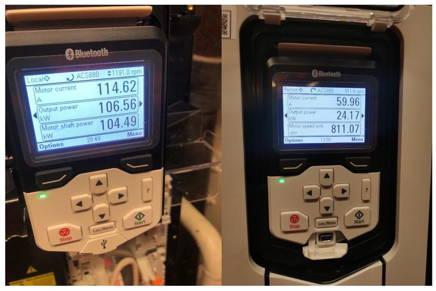
BO21E-20 Improving the efficiency of Deepsea Aberdeen's freshwater cooling system

 7.3 Results .................................................................................................................................... 41
 7.4 Test discussion and conclusions ............................................................................................. 42
8 Energy and cost saving potential ................................................................................................... 45
 8.1 Energy saving potential in the FW cooling circuit .................................................................. 45
 8.2 Energy saving potential in seawater cooling circuit............................................................... 46
 8.3 Seawater Simulation .............................................................................................................. 47
 8.4 Total savings ........................................................................................................................... 49
9 Commissioning Procedure ............................................................................................................. 51
10 Discussion ................................................................................................................................... 52
 10.1 Vibrations in freshwater pump .............................................................................................. 52
 10.2 Cement unit not getting sufficient flow ................................................................................. 53
 10.3 Uncertainty around diesel engines ........................................................................................ 54
 10.4 Uncertainty around seawater sub-system ............................................................................. 55
 10.5 FW temperature exceeding max design temperature........................................................... 55
11 Conclusion .................................................................................................................................. 56
12 References .................................................................................................................................. 57
Appendix A ............................................................................................................................................. 58

Rev: 1.3 Page 6 of 58 31.05.2021
BO21E-20 Improving the efficiency of Deepsea Aberdeen's freshwater cooling system

 Table of Figures
Figure 1. Deepsea Aberdeen .................................................................................................................. 10
Figure 2. Simplified illustration of cooling system. ................................................................................ 12
Figure 3. Illustration of cooling system, which is functionally almost identical for each quadrant. .... 12
Figure 4. Typical layout for a K-Chief 700 control system ..................................................................... 14
Figure 5. Illustration of the current setup(a) and the implementation of the VFD (b) ......................... 16
Figure 6. Simplified model, including VFD and temperature transmitter. ............................................ 17
Figure 7. Unpacking the ABB ACS880 VFD ............................................................................................. 18
Figure 8. Menu selection of the ABB Software interface....................................................................... 19
Figure 9. FBD programming with Abb software..................................................................................... 20
Figure 10. FBD programming for the fans in the du/dt cabinet ............................................................ 20
Figure 11. Network setup, divided into two sub-networks for each quadrant. .................................... 21
Figure 12. Profibus DP-card to make VFD Profibus compatible ............................................................ 21
Figure 13. Thermistor motor protection ................................................................................................ 23
Figure 14. Connection diagram from ABB hardware catalog ................................................................ 24
Figure 16. Mechanical protective case for ABB drive ............................................................................ 25
Figure 17. Pressure transmitter used for pump control and fault detection. ....................................... 26
Figure 18. Sensor connection ................................................................................................................. 27
Figure 19. Proposed designed cabinet for Du/dt filter with sufficient IP rating.................................... 27
Figure 20. SW sensor setup. ................................................................................................................... 28
Figure 21. Festo Pneumatic actuator with CMX poistioner. .................................................................. 31
Figure 22. The Break Resistor. ................................................................................................................ 31
Figure 23. Schematic illustrating control logic and signal flow. ............................................................. 32
Figure 24. The Anchor Winch cooling system. ....................................................................................... 33
Figure 25. One of four Mud pumps. ....................................................................................................... 34
Figure 26. Automated valve and bypass WCCU. .................................................................................... 34
Figure 27. Chiller unit. ............................................................................................................................ 35
Figure 28. FMEA analysis. ....................................................................................................................... 36
Figure 29. Siemens S7-1500 PLC. ........................................................................................................... 37
Figure 30. Testing rig to test VFD software. ........................................................................................... 38
Figure 31. Abb drive composer PID configuration and TIA-Portal. ........................................................ 38
Figure 32. Illustration of the VFD and du/dt filter setup during testing. ............................................... 39
Figure 33. VFD and du/dt filter setup during testing. ............................................................................ 39
Figure 34. Volumetric flow rate formula for ultrasonic flowmeter from datasheet [7]. ....................... 40
Figure 35. Illustration of ultrasonic flowmeter principle. ...................................................................... 40
Figure 36. Different configurations of opened and closed valves during testing. ................................. 40
Figure 37. Power consumption before (left) and after (right) implementing pressure regulator. ....... 42
Figure 38. Pressure data from the pumps discharge side during testing. ............................................. 43
Figure 39. Pressure data from discharge side, with RPM limit .............................................................. 44
Figure 40. Seawater temperature between Orkney and Utsira between 1986-2016. [8] ................... 46
Figure 41. Illustration of sensor locations in the FW system ................................................................. 47
Figure 42. Illustration of data we received. ........................................................................................... 47
Figure 43. Illustration of processed data in our software ...................................................................... 48
Figure 44. Illustration of processed data combined into a single datatype. ......................................... 48
Figure 45. Simulation of SW flow ........................................................................................................... 49

Rev: 1.3 Page 7 of 58 31.05.2021

BO21E-20 Improving the efficiency of Deepsea Aberdeen's freshwater cooling system

Figure 46. Snippet of Commissioning Procedure document ................................................................. 51
Figure 47. FW cooling pump structure................................................................................................... 52
Figure 48. 41.78Hz and 48.25 Hz Total Modal Displacement ................................................................ 53

Rev: 1.3 Page 8 of 58 31.05.2021
BO21E-20 Improving the efficiency of Deepsea Aberdeen's freshwater cooling system

Abbreviations
 FBD Function block diagram

 FW Freshwater

 FWD Forward

 IAS Kongsberg’s Integrated automation system

 MCC Motor control Center

 MODU Mobile offshore drilling unit

 PKW Parameter values

 PLC Programmable Logic Controller

 PT Pressure transmitter

 PZD Process Data

 STBD Starboard

 STO Safe Torque Off

 SW Seawater

 TT Temperature Transmitter

 TV Temperature control valve

 VFD Variable frequency drive

 VSP Variable speed pump

 WCFDI Worst case failure design intent

Rev: 1.3 Page 9 of 58 31.05.2021
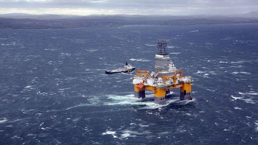
BO21E-20 Improving the efficiency of Deepsea Aberdeen's freshwater cooling system

 1 Introduction
This project report will present a solution to the stated problem of our bachelor thesis at the Western
Norway University of Applied Sciences. The purpose of the thesis is that we, as students, must acquire
knowledge about performing and solving a project together in a group. The problem was given to us
by Odfjell Drilling. They wanted us to look at the possibilities of reducing the energy needed to operate
the central cooling system on Deepsea Aberdeen.

In later chapters, we will describe the steps we will take, how we acquire the necessary and relevant
information to find a solution. In the main part of the report, we will describe the specifications and
other details that are relevant to the task. Examples of this are the description of hardware, software,
protocols, standards, test procedures and application designs.

 1.1 Contracting entity
Odfjell Drilling is an offshore drilling contractor that specializes in the operation of deep-water, harsh
environment, Mobile Offshore Drilling Units (MODU). The offshore industry is very competitive and
everchanging. The last couple of years there has been an extreme drive to become more
environmentally friendly. This means that for Odfjell Drilling to stay competitive in the market, it is
essential to have the energy efficient rigs.

Odfjell Drilling currently has a fleet of five rigs. In our thesis we will be focusing on Deepsea Aberdeen.
Deepsea Aberdeen is a sixth generation MODU designed for harsh environment areas. The rig was
delivered from Daewoo shipyard in South Korea in 2014. Deepsea Aberdeen has for the last couple of
years operated on the coast of Scotland. The vessel has recently finished its contract and is in the early
stages of new contracts in Norway. As a result of the environmental drive, especially in Norway, the
vessel will be undergoing several upgrades to make it more energy efficient.

Figure 1. Deepsea Aberdeen

Rev: 1.3 Page 10 of 58 31.05.2021
BO21E-20 Improving the efficiency of Deepsea Aberdeen's freshwater cooling system

 1.2 Problem description
With the everchanging environmental standards, Odfjell Drilling has given us the opportunity to have
a look at the rigs cooling systems, with the aim of saving energy. The rig is designed to operate at
maximum load with a seawater temperature of 32 °C. Normally it is operating at a much lighter load
and is currently operating in the North Sea, which has an average temperature span of 6-17 °C.
Currently both the seawater and the freshwater pump operates at full speed even though there is no
need for it. This leads to unnecessary usage of energy and accompanying emissions. The aim of our
bachelor thesis is to design a dynamic control system that actively regulates the cooling system to
reduce the energy consumption onboard.

As the systems stands today, it is quite clear that the cooling system runs inefficiently in terms of fuel
usage. The low temperatures in the North Sea, combined with the amount of cooling needed across
the consumers on the rig makes the current system over dimensioned. This means that the pump is
not required to run at maximum speed to provide enough pressure to uphold the recommended flow
throughout the pipes.

Due to the high pressure from the pump, several pipes were measured to receive higher flow than
recommended, and as such lead to higher erosion of the pipes, which has historically been a problem
on similar rigs. Additionally, higher flow will lead to higher noise levels. We also discovered that valves
were being closed by crewmembers to combat this noise. The of closing valves will result in a pressure
increase in the system. Additionally, it will cause the flow obstructed by the valves to move elsewhere,
leading to increasing the flow through the other pipes/consumers instead. This effectively transfers
the problem to a new location in the system.

 1.3 Cooling System Description
Deepsea Aberdeen is divided into four quadrants, each with its own diesel-powered generators, power
grid and cooling system. Due to the rig's quadrant-based design, we have decided to focus on one of
the quadrants, The Port aft. quadrant, to gain a better fundamental understanding of the system. We
will later in the project do a reduced analysis on the other three regarding the total savings potential.

The cooling systems in each quadrant is functionally almost identical. Each system consists of a
freshwater and a seawater sub-system. The freshwater system is a closed loop pump circuit, while the
seawater system is an open loop pump circuit. The seawater system is used to cool down the
freshwater through a heat exchanger. The purpose of the freshwater circuit is to cool down consumers
on the rig. Typical examples of consumers needing cooling includes Diesel engines, generator,
transformers, and breaking resistors. To illustrate the core functionality of the system, we made a
simplified model shown in figure 2. Figure 3 illustrates that the system consists of many duplicate
components in parallel to each other. This is due to redundancy and maintenance reasons. It is
important to note that the freshwater circuit has most of its consumers in parallel to each other. In
addition, the freshwater is pumped from below sea level to upper deck level, approximately 40 meters
in height.

Rev: 1.3 Page 11 of 58 31.05.2021
BO21E-20 Improving the efficiency of Deepsea Aberdeen's freshwater cooling system

Figure 2. Simplified illustration of cooling system.

Figure 3. Illustration of cooling system, which is functionally almost identical for each quadrant.

The system regulates the temperature of the freshwater circuit through a three-way valve (TV) and a
temperature transmitter. The temperature control system is located at the suction side of the pump,
in front of the heat exchanger. If the temperature is above selected setpoint, which is currently set to
36 ⁰C, the control system will let more water through the heat exchanger. If the temperature is below
the setpoint, more water will bypass the heat exchanger. This temperature regulation must be taken
into consideration when assessing the control strategy of both the freshwater and the seawater circuit.

 1.4 Current energy usage
As the system stands today, it consumes 684 kW of electrical power, equivalent to 6 GWh each year.
All this energy is currently being produced with diesel generators on board the rig, consuming about
1200 tonnes of diesel each year. This amounts to around 3800 tonnes of Co2 and 52 tonnes of NOx
[1], and with the increasing focus on a sustainable industry, reducing this would be a competitive

Rev: 1.3 Page 12 of 58 31.05.2021
BO21E-20 Improving the efficiency of Deepsea Aberdeen's freshwater cooling system

advantage for Odfjell. To put these numbers into perspective, this is equivalent to 375 household's
energy consumption, or 2400 fossil cars greenhouse gas emissions [2]. The cost of running this system
including diesel and environmental taxes [3] [4] is about 9 million NOK annually.

 1.5 Specification of requirements
Project requirements

 • Design an alternative system for freshwater cooling.
 • Evaluate the financial viability of the implementation of VFD and automated valves on
 seawater cooling system.
 • Design an alternative system for seawater cooling.
 • Evaluate the financial viability of the implementation of VFD on seawater cooling system.
 • Execute Failure mode effect analysis on design.
 • Evaluate the effect on climate (CO2, NOx)
 • Make materials list.
 • Create necessary documentation for Kongsberg software implementation.
 • Create ABB Drive software
 • Create commissioning procedures.

Technical requirements

 • Redundancy according to rig design philosophy
 • Automated/remote operated flow control on consumers with high wastage

 1.6 Redundancy philosophy
The design philosophy of Deepsea Aberdeen follows DNV-GL recommended guidelines for system
design on dynamic position (DP) vessels [5]. By definition, a dynamic positioning vessel automatically
maintains its position exclusively by means of controlled thrust. Deepsea Aberdeen is designed to a
DP-3 standard, which is the highest tier of standard in its classification. The DP-3 classification requires
that the vessel will not lose its position due to a single failure of any critical systems such as, generators,
thrusters, or switchboards. The DP-3 classification also requires the loss of an entire
subdivision/redundancy group due to a fire or a flooding should not hinder the vessels DP
compatibilities. It is important to understand that the central cooling system delivers cooling to critical
systems onboard, therefore it is important for us to take the DP-3 requirements into consideration
when making changes to the system.

Deepsea Aberdeen is equipped with a K-Chief 700 control and monitoring system delivered by
Kongsberg Marine. The system is a fully integrated automation system covering Power management,
machinery, propulsion, and safety system. The systems are built on a distributed IO and control design,
placing the IO’s closer to the process, making it flexible and redundant. The layout below shows a
typical K-Chief 700 system. All the upgrades that we will be done to the central cooling system will
have to be integrated into the K-Chief machinery control system.

Rev: 1.3 Page 13 of 58 31.05.2021
BO21E-20 Improving the efficiency of Deepsea Aberdeen's freshwater cooling system

Figure 4. Typical layout for a K-Chief 700 control system

 2 Main Solutions Ideas
The project is divided into three technical sub-projects and a sub-project that focuses on budgeting
and the saving potential of the technical solutions. The three technical sub-projects are VFD
implementation on freshwater system, implementation of automated valves and VFD implementation
on seawater system. We will discuss the main ideas for these in this section of the report. The next
section, 2.1, will cover some information on power consumption and total pressure head.

 2.1 General Information
As you can see in the formula for Power consumption (P) of a centrifugal pump in a closed loop system.
The only two independent variables are Flow rate (Q) and Pump Head (H). Meaning that to reduce the
power consumption, we must reduce these. The pump head is the total resistance the pump must
overcome. The head is usually measured in Bar or in “meters of head”. Meters of head represents a

Rev: 1.3 Page 14 of 58 31.05.2021
BO21E-20 Improving the efficiency of Deepsea Aberdeen's freshwater cooling system

height of an equivalent static column of water. Information on this topic was based on a document
titled Calculating the Pump Head by Fluid handling Inc.

 ∗ ∗ = ( )
 = = ( 3 /ℎ)
 367∗ = ℎ ( )
 = ( / 3)
 =

The pump head consists of static head, friction head and velocity head. Static head represents the net
change in height. The friction head, which is also referred to as pressure drops, occurs when the water
flows through any component. These are for example heat exchangers, piping, fittings, and more. The
velocity head is the energy required to accelerate water to a higher velocity. In closed loop systems,
such as the FW circuit, the starting point is the same as the ending point. Therefore, the starting
velocity equals the final velocity, so velocity head is not a consideration.

The freshwater cooling system is a closed loop circuit. The pump is required to transport freshwater
from the pontoon level to consumers at the upper deck level, a height difference of approximately 40
meters. Since the system is closed looped, each meter of altitude the water is pumped upwards has
an equal drop in height downwards. Therefore, the system is unaffected by static head. The velocity
head is not considered in closed loop systems as stated earlier. This means that the total pump head,
the resistance the pump must overcome, is entirely the friction head of the system. Where the
pressure drops due to friction is from for example piping, heat exchangers, and various fittings. [6] [7]

 ℎ =
As the system stand today, the pump is either operating fully on or fully off. To make the system more
energy efficient, we must control the speed of the pump. This can be done by modifying the existing
system and installing a Variable frequency drive (VFD) allowing us to control the pump speed.

 2.2 VFD implementation on the freshwater system
Controlling the pump with a variable frequency drive (VFD) can reduce energy consumption by
regulating the output pressure of the pump. Ensuring sufficient flow through consumers while
reducing setpoint pressure can significantly reduce power consumption. Regulating for constant
setpoint pressure also gives us the ability to close valves of individual consumers without increasing
pressure in the system.

Rev: 1.3 Page 15 of 58 31.05.2021
BO21E-20 Improving the efficiency of Deepsea Aberdeen's freshwater cooling system

 Figure 5. Illustration of the current setup(a) and the implementation of the VFD (b)

 2.3 Implementation of automated valves
As the system stands, the pump is operating at a constant full speed. The valves in the system are also
intended to be fully open, even though we observed that crew members had manually closed them.
The result of closing the valves of consumers is a pressure increase in the whole freshwater system. By
using the synergy effect between using a VFD to regulate for pressure we can close valves to reduce
flow without increasing pressure. This means we can design a control system for automated flow
control for individual consumers of the cooling water.

Our solution idea consists of mounting actuators on existing valves to achieve control over the flow to
these consumers. The valve control system will be able to completely cut off inactive consumers. This
will lead to a reduction flow, which means the pump must work less to maintain the setpoint pressure.
Different consumers may require different control strategies depending on energy savings relative to
cost and risk management. This will be discussed in the technical solution for automated valve system.

 2.4 VFD implementation on the seawater system
The purpose of the seawater cooling system is to reduce the temperature of the freshwater cooling
system. As of now, the system is running at full speed. The solution will be installing a VFD, like the
freshwater cooling system. Instead of regulating for pressure, we will be regulating the temperature
in the freshwater circuit. Essentially, we want to control the circulating flow of the seawater circuit,
depending on the temperature of the freshwater loop. This will substitute the current temperature
regulation of the three-way valve. By doing so we will bypass the existing three-way valve, causing all
the FW to flow through the heat exchangers, reducing the excess SW power wastage.

Rev: 1.3 Page 16 of 58 31.05.2021
BO21E-20 Improving the efficiency of Deepsea Aberdeen's freshwater cooling system

Figure 6. Simplified model, including VFD and temperature transmitter.

Rev: 1.3 Page 17 of 58 31.05.2021
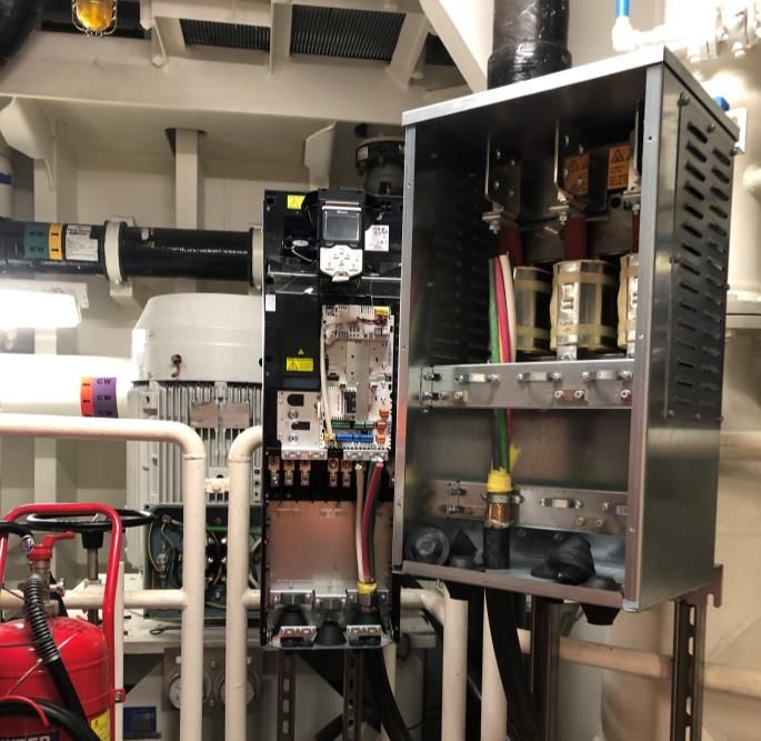
BO21E-20 Improving the efficiency of Deepsea Aberdeen's freshwater cooling system

 3 Freshwater and Seawater VFD Solutions
 3.1 General Solution
In our design we have decided to incorporate a distributed control philosophy. The IAS will be
responsible for sending start, stop and setpoint reference. While the ABB Drive will have full control
over the actual control loop. By doing it this way, we relieve Kongsberg of significant responsibility to
make a more redundant system. In the case of a failure in the IAS, the system will continue to operate
normally. Additionally, we believe that we can reduce the commissioning costs significantly, due to
Kongsberg not having to take the time to finely tune the PID controller. This can be done internally by
Odfjell.

We have decided to use the ABB ACS880 VFD due to how simple the drive is to use and commission in
the field. Additionally, the software for the Drive is extremely user friendly and free to use. When
working on this project we are intending to make the solution simple enough for someone internally
in Odfjell Drilling to commission the drives.

 Figure 7. Unpacking the ABB ACS880 VFD.
BO21E-20 Improving the efficiency of Deepsea Aberdeen's freshwater cooling system

Figure 8. Menu selection of the ABB Software interface.

When we had decided that we were going to go with the ACS880, we had to decide if we wanted to
use the wall mounted drives or the floor mounted drives. In our opinion the decision was quite simple.
The Floor mounted drives are made in Rittal steel cabinet solutions and are notorious for rusting when
placed in harsher conditions. Our intention with this project has always been to make as local as
possible. Placing the floor mounted locally in a Seawater pump room would to some degree be
irresponsible. The wall mounted drives however are made in plastic with a relatively high IP rating of
IP55. The wall mounted drives are also significantly easier to handle due to their smaller frame size.

In addition to the ACS880’s being simple to work with they are also relatively cheap. In the case of one
or multiple drives failing, it is simply cheaper and more cost efficient to replace the whole drive, rather
than having Field Service engineers from ABB come out and repair them. This would not be the case if
we chose to use the floor mounted cabinets.

 Programming the VFD
A big reason for the use of ABB drives is the integrated adaptive programming feature. It is essentially
a simple function block diagram (FDB) programming feature. We will be using this feature to determine
the setpoint pressure for the PID controller and the fan control for the Du/dt cabinet.

One of the features we wanted to incorporate into the drive was that the drive was going to continue
operating normally at the assigned setpoint, even in the case of a communication loss. To do so we
had to create some simple logic to compare the input signal from the PROFIBUS to the last input signal.
In the case that the new input signal is smaller than “1” we know that we have had a communication

Rev: 1.3 Page 19 of 58 31.05.2021
BO21E-20 Improving the efficiency of Deepsea Aberdeen's freshwater cooling system

loss due to all the input signals being “0” in the case of a failure. If this happens, the drive will use the
old value saved in the data storage parameter in the drive.

Figure 9. FBD programming with Abb software

Figure 10. FBD programming for the fans in the du/dt cabinet

 PID controller
A PID controller (proportional-integral-derivative controller) is a control loop system that calculates an
error value based on the current output value and a chosen setpoint value. The PID controller will
correct for this error to decrease it for each loop, until the output value equals the set point value. The
correction is calculated as a sum of three different control terms, a proportional, integral, and
derivative term. The proportional term corrects the current output value proportional to the target
value. As the error approaches zero, so does the correction, meaning that the target value will never
be reached. The integral term increases the error value by combining the previous error values,
ensuring the controller does not stop before the target is reached. However, this will result in
overshoot, as the combined error will not reach zero without going past the target value. The
derivative term slows down the increasing error value from the integral term to minimize overshoot.

Rev: 1.3 Page 20 of 58 31.05.2021
BO21E-20 Improving the efficiency of Deepsea Aberdeen's freshwater cooling system

 Communication Protocol
Each quadrant will consist of two Profibus-networks to ensure redundancy. Each network consists of
a Kongsberg RCU (remote controller unit), one SW pump VFD, and one FW pump VFD. The Kongsberg
RCU will act as the Master, and the VFD’s will act as slaves. Additionally, for the VFD to be Profibus
compatible we must add a Profibus-DP card to one of the free slots on the drive.

Figure 11. Network setup, divided into two sub-networks for each quadrant.

 Figure 12. Profibus DP-card to make VFD Profibus compatible

When deciding on the telegram we wanted we were quite clear on the fact that we did not want to
change any parameter values (PKW) and that we wanted to be able to access as much process data
(PZD) as possible. Therefor we decided to use the PPO 6 telegram, which has no parameter values
and 10 process data.

Rev: 1.3 Page 21 of 58 31.05.2021
BO21E-20 Improving the efficiency of Deepsea Aberdeen's freshwater cooling system

 Telegram Name Cyclic telegram Length

 PPO 6 0 PKW + 10PZD In/Out

PZD – Process data

PKW – Parameter values

Table 1. Input data for VFD.

 Address Name Length Description
 FBA Data out 1 Control Word 16bit See control Word
 description below.
 (Start, Stop, Reset)
 FBA Data out 2 Pressure reference 16bit Pressure reference =
 pressure setpoint in
 IAS*100. Example:
 7.2Bar = 720.

Table 2. Output data for VFD.

 Address Name Length Description
 FBA Data in 1 Status Word 16bit See status Word
 description below.
 FBA Data in 2 Speed % 16bit Range 0-100%
 FBA Data in 3 KW output 16bit Power output = (Value
 from drive)/10000.
 Example: 16000/10000
 = 1.6kW

Table 3. Control commands sent as 16-bit word from IAS to VFD. Relevant bits are highlighted.

 Bit Name Description
 0 (LSB) Off1 Control (Start Stop) True = start, False = stop
 1 Off2 Control ALWAYS TRUE
 2 Off3 Control ALWAYS TRUE
 3 Run ALWAYS TRUE
 4 Ramp out zero ALWAYS TRUE
 5 Ramp Hold ALWAYS TRUE
 6 Ramp In zero ALWAYS TRUE
 7 Reset True = reset alarm and faults
 8 Inching 1 ALWAYS FALSE
 9 Inching 2 ALWAYS FALSE
 10 Remote cmd ALWAYS TRUE
 11 Extr ctrl loc ALWAYS FALSE
 12 User bit0 ALWAYS FALSE
 13 User bit1 ALWAYS FALSE
 14 User bit2 ALWAYS FALSE
 15 (MSB) User bit3 ALWAYS FALSE

Rev: 1.3 Page 22 of 58 31.05.2021
BO21E-20 Improving the efficiency of Deepsea Aberdeen's freshwater cooling system

Table 4. VFD status which is sent as 16-bit word to IAS system. Relevant bits are highlighted.

 Bit Name Description
 0 (LSB) Ready to switch on True = ready
 1 Ready run True = running
 2 Ready ref NA
 3 Tripped True = tripped
 4 Off2 Inactive NA
 5 Off3 Inactive NA
 6 Switch-on inhibited NA
 7 Warning True = warning
 8 At setpoint NA
 9 Remote True = System in remote mode
 10 Above limit NA
 11 User bit0 NA
 12 User bit1 (PT sensor failure) False = Pressure sensor failure. pump stops and stby
 pump has to start
 13 User bit2 (Du/dt cabinet True = high, alarm needs to be displayed in IAS.
 temperature too high)
 14 User bit3 NA
 15 (MSB) NA

 Thermal protection
Thermal protection will be installed to prevent damage caused by overheating. The protection system
will consist of built-in thermistors inside the windings of the motor and a FPTC thermistor protection
module connected to the ABB VFD. The FPTC has two inputs, a fault input, and a warning input. The
fault input triggers the “Safe torque off” function in the drive, limiting all torque generation, essentially
stopping the motor. The warning input generates a warning signal to the drive. This signal is purely for
indicating a fault and has no other function.

 Figure 13. Thermistor motor protection

In the figure below, we can see how the FPTC module must be connected to the motor and the existing
STO IO clamps.

Rev: 1.3 Page 23 of 58 31.05.2021
BO21E-20 Improving the efficiency of Deepsea Aberdeen's freshwater cooling system

 Figure 14. Connection diagram from ABB hardware catalog

 Du/dt filter
A VFD typically creates a lot of noise from the drive output, which can be damaging to the motor. A
VFD produces a lot of fast rising output voltage when converting the DC power source to an AC output,
causing the output voltage to be higher than desired voltage. A typical motor like the one being used
in the experiment is not properly isolated to handle the higher voltage, causing additional stress on
the motor, cable insulation and motor bearings.

To reduce the risk of damaging the motor we will be using a Du/dt filter. A Du/dt filter uses inductors
to reduce the Du/dt-value of the output of the drive, making the outgoing waveforms significantly
smoother. During testing on the rig, the motor would most likely not have taken any damage based on
the short amount of time it was running through the VFD, but it was a precaution we took for safety.

 Figure 15. Voltage and current without filter left, and with filter right.

Rev: 1.3 Page 24 of 58 31.05.2021
BO21E-20 Improving the efficiency of Deepsea Aberdeen's freshwater cooling system

 Upgrading motors for VFD applications
When installing a VFD on a motor, certain requirements need to be met to prevent damage on the
motor. The motor winding insulation, motor bearings and the pump operating speed range are the
major factors that determines if the motor is compatible with a VFD or not. The motor winding
insulation needs to be able to withstand the frequency spikes that may come from the VFD, while the
motor bearings must be protected from potential common mode voltages. These voltages can
potentially build up and discharge through the motor bearings if not properly isolated.

When running a motor through a VFD, the speed of the pump can be set both higher and lower than
the baseline pump speed. This requires the motor to be able to provide itself sufficient cooling with
the reduced fan speed that comes with reduced rpm. When driven at higher speed, the pump
operating speed range must be great enough to not overload the motor, as the increase in power draw
is proportional to the speed increase cubed. Taking these requirements into consideration, the current
motor on the rig needs to be upgraded to new ones that meets the requirements. [8]

 Mechanical protection for ABB Drives
When we initially proposed to install the VFD’s locally in the pump room, the crew were worried that
the drives would be exposed to excess mechanical abuse due to the extensive work and service that
takes place in these rooms. In order protect the VFD’s from this abuse, we decided to design a simple
stainless-steel enclosure.

 Figure 15. Mechanical protective case for ABB drive

 3.2 Freshwater VFD
Onboard Deepsea Aberdeen there are eight main freshwater cooling pumps, two in each pump room.
All the pumps will be fitted with Variable frequency drives (VFD) to actively regulate the flow of the
FW cooling system by regulating for pressure. The relevant pumps and sensors are listed below:

Rev: 1.3 Page 25 of 58 31.05.2021
BO21E-20 Improving the efficiency of Deepsea Aberdeen's freshwater cooling system

 Tag Description Disch. PT
 722-PA-001A FRESHWATER COOLING PUMP PORT FWD 722-PT-103
 722-PA-001B FRESHWATER COOLING PUMP PORT FWD 722-PT-106
 722-PA-001C FRESHWATER COOLING PUMP STBD FWD 722-PT-203
 722-PA-001D FRESHWATER COOLING PUMP STBD FWD 722-PT-206
 722-PA-002A FRESHWATER COOLING PUMP PORT AFT 722-PT-303
 722-PA-002B FRESHWATER COOLING PUMP PORT AFT 722-PT-306
 722-PA-002C FRESHWATER COOLING PUMP STBD AFT 722-PT-403
 722-PA-002D FRESHWATER COOLING PUMP STBD AFT 722-PT-406

 Freshwater VFD software
The VFDs for the FW pumps will be controlled by the IAS via Profibus-DP communication. The existing
Main/standby pump logic will remain as is. The existing power fault detection is to be eliminated and
replaced with pressure fault detection logic. In the following cases below, the main pump is to stop,
and the standby pump is to start:

 - VFD Tripped
 - VFD Pressure fault
 - VFD Pressure sensor failure

In the case of a fault, the control room operator has the option to reset the fault in IAS. In the case of
communication failure, the IAS is only to start backup pump when a pressure drop is detected, or if
manually overridden. Even with a communication failure the VFD should continue to work normally,
running on integrated controller unless it has had a power loss.

The VFDs speed will be determined by a pressure controller integrated in the VFD’s software. The
pressure setpoint will be written to the VFD by IAS as a 16 bit integer. The VFD will be connected to
the relevant PT sensor in series with the IAS, giving both the VFD and IAS access to the same PT data.
Speed in percent and power output in kW is to be displayed on IAS control panel. In the case of High
Du/dt temp, a warning is to be displayed on control panel and recommended to change drive.

Figure 16. Pressure transmitter used for pump control and fault detection.

 Pressure transmitter
For the VFD to obtain the same pressure transmitter signal as the IAS, it was determined that is would
be most suitable and cost efficient to connect to the existing pressure transmitter in series with the
RCU. By connecting the VFD directly to the PT we can increase the sample rate and eliminate the 100ms

Rev: 1.3 Page 26 of 58 31.05.2021
BO21E-20 Improving the efficiency of Deepsea Aberdeen's freshwater cooling system

delay that would occur if we were to be forwarded the signal from the RCU. See figure below for sensor
connection diagram.

Figure 17. Sensor connection

 Du/dt cabinet for FW VFD
Due to ABB not being able to supply a Du/dt filter with a sufficient IP rating for the FW VFD, we had to
design out own cabinet solution. The required IP rating for electrical equipment in pump rooms
according to DNV GL is IP44 [5], ABB only Supplies Du/dt enclosures up to IP22.

 Figure 18. Proposed designed cabinet for Du/dt filter with sufficient IP rating.

 Specification for supplier

 Description Quantity
 Rittal stainless steel 316 cabinet 500x5000x300 1
 ABB Du/dt filter FOCH0260-70 1
 Rittal 230V fans 2
 Rittal exhaust filter 2
 Temperature transmitter 1

The proposed design makes it possible for the VFD to control the temperature of the cabinet with the
use of the integrated IO’s and relays. The 230V Power from the fans will obtained from the existing
space heaters for the old motors. By using this as the power source, the power will come from the
same MCC as the motor, eliminating issues regarding getting power from other redundancy groups.

Rev: 1.3 Page 27 of 58 31.05.2021
BO21E-20 Improving the efficiency of Deepsea Aberdeen's freshwater cooling system

 3.3 Seawater VFD
There are eight main seawater cooling pumps. Two in each pump room for cooling the FW cooling
system via the central water coolers/heat exchangers. One pump in each quadrant will be fitted with
a VFD will be implemented on the SW system to actively regulate the flow of the SW control the FW
cooling system temperature.

 Tag Description Freshwater TT tag.
 721-PA-001A MAIN SEAWATER COOLING PUMP PORT FWD TBC
 721-PA-001C MAIN SEAWATER COOLING PUMP STBD FWD TBC
 721-PA-002A MAIN SEAWATER COOLING PUMP PORT AFT TBC
 721-PA-002C MAIN SEAWATER COOLING PUMP STBD AFT TBC

 Seawater VFD software
The VFDs for the SW pumps will be controlled by the IAS via Profibus-DP communication. The existing
Main/standby pump logic will remain as is. The existing low pressure fault detection is to be eliminated
and replaced with FW temperature low detection. In the following cases below, the main pump is to
stop, and the standby pump is to start:

 - VFD Tripped
 - VFD Warning
 - VFD not able to obtain setpoint temperature.

In the case of a fault, the control room operator has the option to reset the fault in IAS. In the case of
communication failure, the IAS is only to start backup pump when a pressure drop is detected, or if
manually overridden. Even with a communication failure the VFD should continue to work normally,
running on integrated controller unless it has had a power loss.

The VFDs for the SW pumps will be controlled by the IAS via Profibus-DP communication. The motor
speed will be determined by a temperature controller integrated in the VFDs software. The
Temperature setpoint will be given to the VFD by IAS. The VFD will be connected to a separate
Temperature transmitter. The existing temperature transmitter will be used by the IAS to monitor the
system. In the case of the VFD not being able to obtain the setpoint, the standby pump is to be started.

Figure 19. SW sensor setup.

Rev: 1.3 Page 28 of 58 31.05.2021
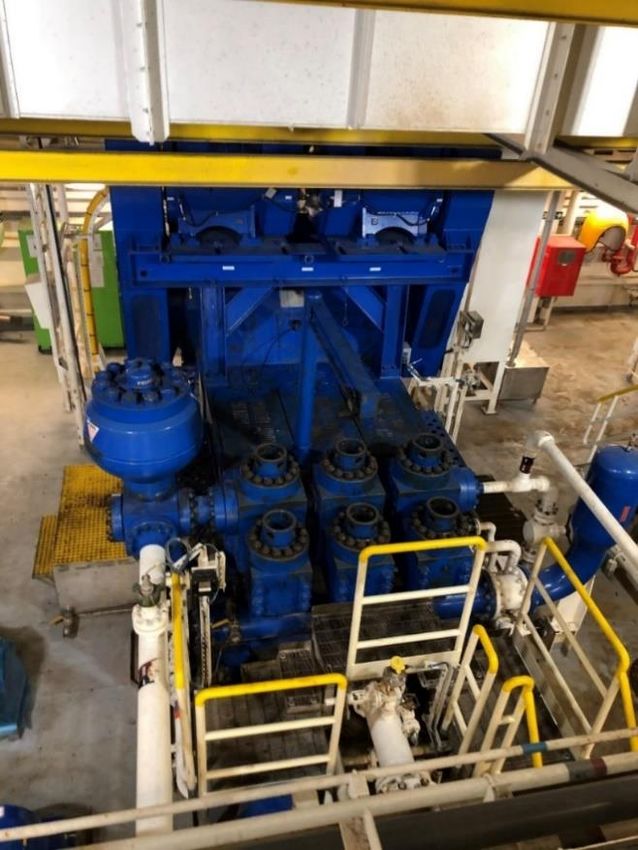
BO21E-20 Improving the efficiency of Deepsea Aberdeen's freshwater cooling system

 Temperature transmitter
The temperature sensor to be used is an ABB TSP341-N non-invasive temperature sensor. This
temperature sensor is mounted on outside of the pipe without the need to drill a hole or shutting
down the system. The temperature sensor measures temperature using an algorithm containing the
parameters: wall temperature, measuring medium temperature, ambient temperature, medium
velocity, pipe diameter and dynamic viscosity. The calculated temperature is sent via a 4-20mA analog
signal from a temperature transmitter with a response time of T90 < 30s for rapid changes in
temperature. This means the measurement will be within 90% of the actual temperature in less than
30 seconds, see datasheet [9] for information on the ABB TSP341-N. Additionally, the response time
of the sensor will also be dependent on the flow in the system. We believe this is a sufficient response
time as the system has circulating water that should slow a potential temperature increase.

 Figure 20. ABB non-invasive temperature sensor TSP341-N

Rev: 1.3 Page 29 of 58 31.05.2021
BO21E-20 Improving the efficiency of Deepsea Aberdeen's freshwater cooling system

 4 Flow control to consumers
 4.1 Introduction
In this section of the report, we will discuss our proposed design for the automated valve system. For
more information about specifications of the system please see Appendix. The document is titled
Functional description and design changes to DAB cooling system.

The implementation of automatic valves can only be applied after the implementation of a VFD, which
regulates the speed of the pump to achieve a constant setpoint pressure. As the system stands, using
a constant speed pump, the closing of valves will result in a pressure increase. This pressure increase
will be counteracted by the VFD, which is regulating for constant pressure setpoint. This allows us
reduce flow in pipes by closing the valves. This was also verified during testing on the rig, as discussed
later in section 7.4. The result of closing valves is a reduction of the head required to maintain the flow.

Additionally, the friction loss will decrease proportionally with a reduction in flow in a well-designed,
closed loop system [7]. Assuming the FW system is a well-balanced and designed system, the reduction
of flow should make the system run at a more optimal state regarding efficiency and erosion. In
summary, this will allow us to optimize the system by designing a control system for automated flow
control for individual consumers of the cooling water.

 4.2 Actuator choice
The valves we want to control are quarter-turn butterfly valves. For some consumers we want an
actuator to control the valve to a precise position between 0-90 degrees. For other consumers we want
an actuator to completely open or close the valve. In both cases we goal is for valve to regulate
depending on temperature. According to DNV-GL guidelines for design, found in section 7.4.6, the fail-
safe condition for temperature regulating valves in freshwater cooling systems should be fail open [5].
This will ensure no harm on the consumers due to lack of cooling.

When choosing suitable actuators for our project we considered cost of component, installation costs
and risk management. We ended up choosing pneumatic powered actuators for our application. The
main advantages of pneumatic actuators are their simplicity, they are affordable, and we have easy
access to pressurized air. Pneumatic actuators can easily be equipped with fail-safe option. A spring-
loaded actuator will be chosen for both applications to mechanically open the valve in case of any
detected failure.

We will need two types of pneumatic actuators, one for binary control (fully open or closed) and one
for position control. Both will use spring loaded single acting pneumatic actuators. The spring allows
the actuator to open the valve in case of failure. For the position control, to regulate the actuator for
a setpoint position, we will need an additional positioner component which attaches to the actuator.

Rev: 1.3 Page 30 of 58 31.05.2021
BO21E-20 Improving the efficiency of Deepsea Aberdeen's freshwater cooling system

Figure 21. Festo Pneumatic actuator with CMX poistioner.

 4.3 The Break Resistor cooler control system
The Break Resistor cooler is a consumer of the cooling system consisting of a resistor which takes
excess electric energy that is generated by draw works or anchor winches. This consumer requires
different amounts of cooling depending on the activity of the rig. Even with low activity, the break
resistor will still need cooling. Therefore, we want dynamic flow control for The Break Resistor cooler.
We will achieve this by regulating for setpoint temperature using an existing temperature transmitter
within the consumer. The actuator choice is a single acting pneumatic actuator with a positioner. Single
acting means the actuator only needs one air intake. The positioner is a control loop that regulates the
position from position feedback measurement, which is located within the positioner.

 Figure 22. The Break Resistor.

Rev: 1.3 Page 31 of 58 31.05.2021
BO21E-20 Improving the efficiency of Deepsea Aberdeen's freshwater cooling system

The goal of this control system is to regulate the temperature of the cooling water. The figure shows
the control schematic for The Break Resistor control valve. It consists of an inner and an outer feedback
loop in cascade. It is important to note that the inner loop is the positioner component which is
mounted on the actuator. The system rescieves a setpoint temperature (default is 36 °C). The setpoint
is compared to the measured feedback signal to generate a temperature error signal. This error signal
goes through the PID controller to genereate a position gain. The position gain is compared to the
actual positon of the valve through messurement and the error is sent to the position controller, which
adjusts the position of the valve. Ultimately, the control system will dynamically regulate the flow by
adjusting the valve position of the consumer depending on a temperature messurement and setpoint.

Figure 23. Schematic illustrating control logic and signal flow.

The control room operator can override the temperature setpoint in the IAS system. The operator is
also able to open an close the valve with manual ovveride. The standard PID-controller was chosen
due to being simple and effective.

4.4 The Anchor Winch cooler control system
There are four different anchor winches, one for each quadrant. The anchor winches are only used
when deploying or raising the rigs anchors and will therefore be inactive most of the time. However,
when they are in use, they are considered critical consumers and requires sufficient cooling. For this
consumer we want to control flow with a binary control strategy, either open or closed, based on a
setpoint temperature.

Each anchor winch has an individual closed loop cooling circuit with a heat exchanger towards the main
freshwater circuit. Most of the time the local cooling circuit provides enough cooling, but when more
cooling is needed the valve on the main freshwater circuit will open and run through the heat
exchanger, determined by the temperature in the local circuits. This will be measured by adding a non-
invasive temperature transmitter to each of the systems which will constantly signal the current
temperature to the IAS. A pneumatic actuator will be added to the main freshwater circuit by each of
the anchor winches to control flow through the heat exchanger. The actuator will open the valve by
signal from the IAS based on the measured temperature.

The actuators used are spring loaded and set to having the valve normally open. This will ensure that
in the event of signal loss, power loss, pressure loss in the pneumatic actuator or if the positional
sensor of the valve does not correspond with the valves current setpoint, the valve will always be
opened to prevent damage on the anchor winch due to lack of cooling. This event will also send an
alarm to the IAS monitoring system.

Rev: 1.3 Page 32 of 58 31.05.2021
You can also read