Cancer cell enrichment on a centrifugal microfluidic platform using hydrodynamic and magnetophoretic techniques
←
→
Page content transcription
If your browser does not render page correctly, please read the page content below
www.nature.com/scientificreports
OPEN Cancer cell enrichment
on a centrifugal microfluidic
platform using hydrodynamic
and magnetophoretic techniques
Amir Shamloo*, Amin Naghdloo & Mohsen Besanjideh
Isolation of rare cancer cells is one of the important and valuable stages of cancer research. Regarding
the rarity of cancer cells in blood samples, it is important to invent an efficient separation device for
cell enrichment. In this study, two centrifugal microfluidic devices were designed and fabricated for
the isolation of rare cancer cells. The first design (passive plan) employs a contraction–expansion
array (CEA) microchannel which is connected to a bifurcation region. This device is able to isolate the
target cells through inertial effects and bifurcation law. The second design (hybrid plan) also utilizes
a CEA microchannel, but instead of using the bifurcation region, it is reinforced by a stack of two
permanent magnets to capture the magnetically labeled target cells at the end of the microchannel.
These designs were optimized by numerical simulations and tested experimentally for isolation of
MCF-7 human breast cancer cells from the population of mouse fibroblast L929 cells. In order to
use the hybrid design, magnetite nanoparticles were attached to the MCF-7 cells through specific
Ep-CAM antibodies, and two permanent magnets of 0.34 T were utilized at the downstream of the
CEA microchannel. These devices were tested at different disk rotational speeds and it was found
that the passive design can isolate MCF-7 cells with a recovery rate of 76% for the rotational speed of
2100 rpm while its hybrid counterpart is able to separate the target cells with a recovery rate of 85%
for the rotational speed of 1200 rpm. Although the hybrid design of separator has a better separation
efficiency and higher purity, the passive one has no need for a time-consuming process of cell labeling,
occupies less space on the disk, and does not impose additional costs and complexity.
Cell separation is a basic and essential stage of many biological investigations, especially in the field of single
cell analysis1 and drug d evelopment2. In the last two decades, microfluidic technology has provided different
techniques for separation and sorting various biological components based on their physical and chemical
properties. Generally, these techniques are categorized into three main groups, including passive, active, and
hybrid (combined) t echniques3. Active methods utilize an external force field for cell separation and manipu-
lation while the passive ones just rely on the interaction of particles with the flow field and the geometry of
microchannels. Obviously, the hybrid methods are the combination of passive and active separation methods
which profit from the abilities of both methods. The main advantage of the passive methods is its no need for
the external force for separation. This feature leads to rapid and low-cost separation. Also, the viability of the
cells can be preserved admissibly due to the absence of external force. The main examples of passive methods of
separation include pinch flow f ractionation4, deterministic lateral d
isplacement5, and employing inertial effect
such as dean flow fractionation6 and Zweifach–Fung effect7. On the other hand, active methods can provide some
special advantages over the passive counterparts. Active methods often have higher throughput and separation
efficiency than passive ones. However, they need more equipment, and the cells can probably be damaged by the
external forces used in these methods. Furthermore, most of the active methods suffer from long residence time
and consequently low flow rate because the cells should be sufficiently exposed to the external force field. The
conventional active methods of cell separation include e lectrophoresis8, dielectrophoresis9, magnetophoresis10,
acoustophoresis11, and optical tweezers12. Hybrid methods of separation can be another route for cell separation
and sorting. In this way, the combination of active and passive methods proffers higher sensitivity and tenability
and enhances the ability for multiplex separation13. Moreover, utilizing the advantages of both passive and active
methods can lead to higher separation efficiency and can decrease the time and cost of the separation process.
Department of Mechanical Engineering, Sharif University of Technology, Tehran, Iran. *email: shamloo@sharif.edu
Scientific Reports | (2021) 11:1939 | https://doi.org/10.1038/s41598-021-81661-2 1
Vol.:(0123456789)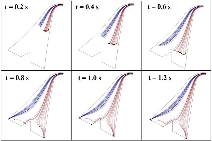
www.nature.com/scientificreports/
Figure 1. Effect of bifurcation region on separation of particles. Particles placed above the critical streamline
are drawn into the high-flow-rate branch while those located under the critical streamline are conducted to the
low-flow-rate branch.
In addition to the method of separation, microfluidic platform is another important issue that can affect the
quality of the separation. Rotating platform (also known as ‘Lab-on-a-CD’) is one of the promising microfluidic
platforms for conducting biological assays. On this platform, fluid flow is supplied by centrifugal force. So,
syringe pumps and all the other external interconnections are eliminated. Also, fluid controlling can be easily
done by using simple passive v alves14. This platform has been employed in the integrated biosensors to achieve
a high-sensitivity detection of pathogens15 and accelerate gene amplification processes16,17. Furthermore, the
centrifugal force on a spin unit can be employed to separate particles based on size and density. Morijiri et al.18
implemented a pinched-flow structure on a rotating disk, where different particles were placed on their own
pathways based on size and then separated based on size and density in a peripheral channel due to the effect of
centrifugal force. Yeo et al.19 mounted a spiral microchannel on a rotating disk and successfully separated 200
and 500 nm fluorescent nanoparticles at the outlets. They also utilized this device to extract the microvesicles
released from the suspension of MCF-7 and H1975 cell lines. Finally, western blot analysis was conducted to
distinct two different microvesicles through checking the CD63 exosomal marker. Compared with the conven-
tional methods, the proposed device required less operation time and extracted the microvesicles at ten folds
lower rotational speed. Lee et al.20 constructed a four-layer on-disk filtration device to separate CTCs spiked in
a whole blood sample. The sample was driven towards a track-etched polycarbonate membrane by centrifugal
force. The pore size of 8 μm was chosen for the membrane, and MCF-7 cells were trapped on the membrane with
an average efficiency of 61% for the spin speed in the range of 600–3600 rpm. To avoid membrane clogging, the
authors suggested diluting the sample. They also showed that dilution up to 1:3 ratio has no significant effect on
capture efficiency or purity.
Some researchers have employed active methods of separation on the rotating platform to create a more com-
pact and effective device for particle sorting. Kirby et al.21 developed a lab-on-a-CD magnetophoretic scheme to
separate magnetically-tagged particles and cells from a background population. The target cells were specifically
labeled with magnetic beads and deflected towards an on-CD permanent magnet inside the stagnant carrier flow.
A similar pattern was employed by Glynn et al.22 to separate CD4-positive cells (HL60) from different spiked sam-
ples. The samples were treated with Dynabeads CD4 magnetic beads, and the specific bindings were just formed
between HL60 cells and Dynabeads. The results depicted that more than 80% of the target cells would be isolated
from different spiked samples. However, when two types of human cells (HL60 as CD4-positive, and HeLa as
CD4-negative) were spiked in the sample, the purity of the isolated target cells would be decreased due to some
cell–cell interactions. Chen et al.23 designed a multistage centrifugal microfluidic device that captures magneti-
cally labeled non-target cells. Capillary valves were employed to connect the device stages, and four ring-shaped
magnets were located on the device to maximize the magnetic binding force. To fulfill the aim of each stage, the
device was rotated based on a specific rotational protocol in the range of 0–1000 rpm. MCF-7 cells were used
as the rare target cells in two different spiked samples with a large number of Jurkat cells and mononuclear cells
(MNCs). Separation yields were determined for 10 to 1000 MCF-7/106 Jurkat cells and ~ 47 MCF-7/106 MNCs.
The results depicted an average yield of 60 ± 10 for all the experiments. To remove the requirement of the cell
labeling process, Shamloo and B esanjideh24 suggested utilizing negative magnetophoresis on a rotating disk. The
proposed device was reinforced by a dual-purpose permanent magnet that could participate in mixing the sample
and ferrofluid and also exert the magnetic repulsive force on the particles. The results depicted that the combina-
tion of centrifugal and magnetic force can improve recovery rates for binary and ternary separation of particles.
The main aim of this study is to introduce a low-cost and simple separation device which can rapidly isolate
the rare cells with proper efficiency. Therefore, in the first step, we considered designing a passive separator using
just inertial effects on the rotating platform. To this end, combination of a bifurcation region and a contrac-
tion–expansion array (CEA) microchannel is considered. Employing a bifurcation region can be considered as a
simple and effective passive technique of separation. Based on the bifurcation law, when a suspension of particles
flows through a bifurcation region, most of the particles are attracted to the high-flow-rate branch while fewer
particles travel into the low-flow-rate branch. This phenomenon is also known as Zweifach–Fung effect and can
be explained by the pressure gradient and shear stress distribution applied to the p articles25. Figure 1 depicts
how bifurcation law conducts most of the particles towards the branch with a higher flow rate. If centers of the
particles are located above the critical streamline, they are drawn into the high-flow-rate branch. Otherwise,
Scientific Reports | (2021) 11:1939 | https://doi.org/10.1038/s41598-021-81661-2 2
Vol:.(1234567890)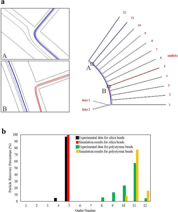
www.nature.com/scientificreports/
particles are conducted towards the branch with the lower flow rate. It should be noted that the critical streamline
is placed near to the low-flow-rate branch, and it approaches more to this branch by increasing the flow rate
ratio between two branches. Yang et al.25 introduced a microfluidic device for blood plasma separation using
bifurcation law. Also, Geng et al.26 utilized bifurcation law for separation of plasma from whole blood sample.
Their device was also reinforced by centrifugal and diffuser-nozzle effects.
On the other hand, particle focusing and separation can be performed by using inertial hydrodynamic forces.
Along a straight microchannel with a parabolic velocity profile, equilibrium positions of particles are determined
by balancing wall-induced and shear-induced lift forces. However, in a curved channel, the curvature can induce
secondary flow, which exerts Dean drag force to the particles. Balancing lift and Dean drag forces determine
the equilibrium positions of p articles27. De Carlo et al.28 used an asymmetric curved microchannel for particle
focusing. Also, spiral microchannels can employ the Dean drag force to focus and separate the particles29,30. It
has been observed when particles pass through a straight channel with successive contractions and expansions
(CEA microchannel), they experience Dean drag force similar to that exerted on particles into a curved chan-
nel with constant cross-section31,32. In the entrance of the contraction region, particles are affected by Dean
drag forces. However, passing through the contraction region, particles also experience the inertial lift forces33.
Therefore, a force balancing determines the migration routes of the particles into a CEA microchannel based
on the size of particles.
In the second step of this study, the construction of a simple hybrid microseparator was intended so that
separation efficiency would be enhanced notably. Therefore, the combination of a CEA microchannel and a
magnetophoretic separation technique was considered. Among all conventional active methods, it seems that
magnetophoresis is more proper for the separation of rare cells from the blood samples. Magnetic force interacts
indirectly with the cells and does not jeopardize their v iability34. Furthermore, in magnethophoretic assays, the
target cells are labeled by magnetic nanoparticles through antigen–antibody complexes. So, in addition to the
physical properties, the biological properties of the target cells are involved in separation and consequently, more
separation efficiency would be expected.
As deduced from the literature, achieving a simple and effective separation plan is still an unresolved problem
for the enrichment of the rare cells. Most of the proposed devices suffer from low purity and recovery rates or
have complex designs and impose high costs for mass production. The pivotal reason for this challenge should
be sought in the complex hydrodynamic behavior of particle suspensions. Recently, computational models have
been widely used to design more effective lab-on-a-chip systems35,36. Hence, our plans were optimized based
on numerical particle tracing simulations such that the on-disk hydrodynamic phenomena can be utilized for
the separation goal. Moreover, experimental results confirm that the proposed plans would be used simply and
offer high separation efficiency.
Theory
Device description. Figure 2a shows the passive design of the separation device, which utilizes both inertial
hydrodynamic forces and bifurcation law for cell enrichment. This device comprises a peripheral CEA micro-
channel, which is directly connected to a bifurcation region at its last part. Centrifugal force acts on particles
inside the inlet chamber and drives them into the peripheral CEA microchannel, where particles are aligned on
their equilibrium paths through force balancing. It has been proven that by utilizing a CEA microchannel on a
stationary platform, particles are sorted based on the size by balancing lift and dean drag forces31. However, on
the rotational platform, centrifugal force, which is a size-dependent force, also acts effectively to separate two
different-sized particles. At the end of the CEA microchannel, the fluid flow is divided into two branches of
non-equal flow rates to utilize bifurcation phenomena for cell separation. Design of this region was optimized
by numerical simulations so that the target cells are placed on streamlines below the critical streamline and
conducted to the low-flow-rate branch, which pours into the target chamber. On the other hand, most of the
non-target cells are conducted towards the upper side of CEA microchannel by the effect of inertial forces and
flow through the high-flow-rate branch, which pours into the non-target chamber. Therefore, two different-sized
particles can be separated by employing the inertial effects of CEA microchannel and bifurcation law.
To employ the hybrid design of the separation device, the bifurcation region is replaced with a magnetic
region at the end of the CEA channel. Therefore, the magnetically tagged cancer cells would be captured by the
permanent magnets. Figure 2b shows the desired hybrid design of separator, which takes advantage of inertial
forces and magnetophoretic separation technique for cell enrichment. Figure 2c shows the four-sector centrifugal
platform fabricated by CNC micromachining.
Governing equations. The governing equations of fluid flow consist of continuity and momentum equa-
tions of Newtonian and incompressible fluid flow which are expressed as follow:
� =0
∇ ·V (1)
� ·∇ V � + f�b
� = −∇P + µ∇ 2 V (2)
ρ V
where V is the velocity vector ( ms−1), P is pressure (Pa), and ρ and µ represent density (kg m −3) and dynamic
viscosity (Nsm−2) of fluid, respectively. f b denotes the body forces
−
→ (
Nm −3
), which consists of centrifugal force
(ρ ω � ), Coriolis force ( 2ρ V
� × (�r × ω) � ×ω � ), and Euler force (ρ ω̇ × �r ). ω
and r refer to angular velocity and
distance from the center of rotation, respectively. It should be noted that Euler force is neglected supposing
constant disk rotational speed.
Scientific Reports | (2021) 11:1939 | https://doi.org/10.1038/s41598-021-81661-2 3
Vol.:(0123456789)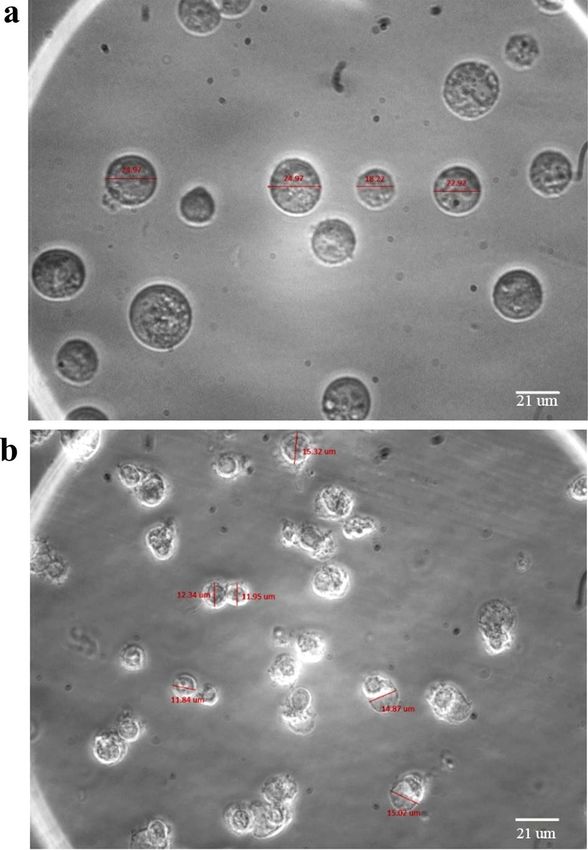
www.nature.com/scientificreports/

                                            Figure 2.  Schematic illustration of the separation device. (a) Passive design. (b) Hybrid design. (c) Device
                                            fabricated by CNC micromachining of a plexiglass plate.

                                               To determine the trajectory of particles, the Lagrangian approach of Newton’s second law of motion is con-
                                            sidered as follows:
                                                                            d 2 �rp
                                                                       mp           = F�drag + F�lift + F�centrifugal + F�Coriolis + F�magnetic             (3)
                                                                            dt 2

          Scientific Reports |   (2021) 11:1939 |                https://doi.org/10.1038/s41598-021-81661-2                                                  4

Vol:.(1234567890)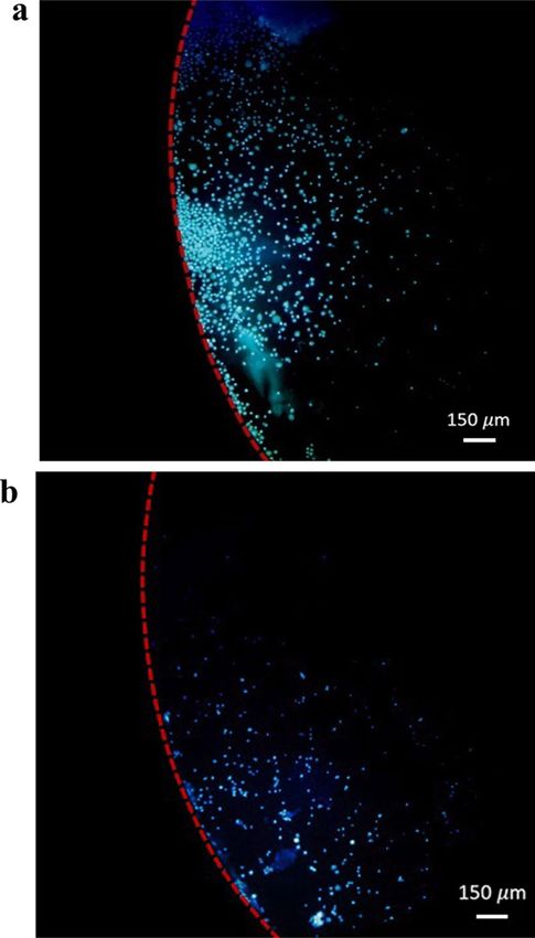
www.nature.com/scientificreports/
During the numerical simulation of this work, fluid velocity and pressure fields were obtained by simultane-
ously solving Eqs. (1) and (2). Then, the trajectories of the particles were determined by employing Eq. (3). It
should be noted that the magnitude of forces mentioned in this equation is dependent on the particle Reynolds
number defined as follows:
ρdp V − Vp
Rep = (4)
µ
where dp is the particle diameter and V , and Vp denote fluid and particle velocities, respectively. Drag force action
on a particle with mass of mp can be obtained by applying Stokes drag force as bellow:
1
Fdrag = mp V − Vp (5)
τp
In order to consider the effect of fluid inertia on drag force, τp is calculated by Schiller-Naumann correlation
as follows37:
4ρp dp2
τp = (6)
3µCD Rep
where
24
CD = 1 + 0.15Rep0.678 (7)
Rep
Total lift force acting on the particles is the result of shear-induced and wall-induced lift forces which can be
calculated by an overall relation suggested by Asmolov38 for Rep < 1 :
2 d4
Cl Um p
Flift = (8)
Dh2
where Cl is the lift coefficient, which depends on the location of particles in the cross-section of the channel. Um
is the maximum flow velocity, and Dh is hydraulic diameter defined as 2wh/(w + h) (w and h denotes width and
height of channel, respectively).
On the centrifugal platform, particles are affected by centrifugal, Coriolis, and Euler forces. Euler force is
often ignored, assuming constant angular velocity. Centrifugal force is exerted on particles radially outwards
from the center of rotation, while the Coriolis force acts perpendicular to angular velocity and particle velocity
vectors. These forces can be calculated by the following equations:
F�centrifugal = mp ω (9)
� × �rp × ω
�
F�Coriolis = 2mp V
� ×ω
� (10)
By applying magnetophoretic technique of separation, magnetic force is exerted on particles labelled with
magnetite nanoparticles. This force can be expressed a s39:
χp − χm
F�magnetic = � .∇ B
�
2µ
Vp B (11)
0
where χp, and χm are magnetic susceptibilities of particle and surrounding medium, respectively. Vp is the par-
ticle volume. B
denotes magnetic flux density (T), and µ0 is permeability of the free space ( 4π × 10−7 Hm−1).
Experimental setup
Microfluidic device fabrication. Two desired designs of the microfluidic device were fabricated using
CNC micromachining of plexiglass plates. The circular plexiglass plates are 0.6 mm thick with a diameter of
120 mm. A 0.2 mm milling bit was used to carve out the patterns of the device into a plate with a depth of
0.2 mm. A second circular plate of the same size was used to close and finalize the microfluidic designs. Vents
and sample loading port on both plans were drilled as through holes on this second plate using the same milling
bit. Afterward, the pair of plates were bonded to each other using a double-sided pressure-sensitive adhesive
(PSA). To reduce the surface roughness of the microchannels, the patterned surface was polished with acetone
as a weak solvent of plexiglass. To this end, the method of Ogilvie et al.40 was used. Based on this method, the
acetone container is placed inside a steam bath, and due to the low evaporation point of acetone (55 °C), acetone
is vaporized and sprayed onto the plexiglass plate to smooth the machined surface.
The final fabricated centrifugal platform is depicted in Fig. 2c, which consists of two passive and two hybrid
designs of the separator. As is shown in this Figure, the hybrid designs are supported with a stack of two NdFeB
permanent magnets at the downstream of the CEA channel. Finally, to operate the microfluidic device, the disk
was mounted on a rotational apparatus, where the desired rotational speed is adjusted through a PID control-
ler and measured by an optical sensor. Figure S1 depicts a schematic of the electronic circuit of the rotational
apparatus.
Scientific Reports | (2021) 11:1939 | https://doi.org/10.1038/s41598-021-81661-2 5
Vol.:(0123456789)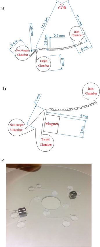
www.nature.com/scientificreports/
Figure 3. Electron microscopy images of the target and non-target cells in the vicinity of magnetite
nanoparticles. (a) Binding of magnetite nanoparticles and MCF-7 cells through specific EP-CAM antibodies. (b)
Nanoparticles are not bonded to L929 cells.
Cell counting. To detect the target cells from non-target ones, cell staining method was used. According to
this method, the target cells were stained with DAPI fluorescent dye, and two identical optical and fluorescence
microscopy images were provided from the samples collected from each outlet chamber. Figure S2 illustrates
both optical and fluorescent images taken from a part of the sample extracted from the target chamber of the
passive separation device. Both stained and unstained cells can be seen in the optical image while in the fluores-
cent image, just stained cells are observed. Thereby, the target cells can be distinguished from the population of
the non-target cells. To quantify the cell numbers, a Python image processing library was used. The stained cells
of each outlet were counted via the fluorescent image while the number of unstained cells can be determined by
counting the cells observed in the optical image and subtracting from the stained cell numbers.
Synthesis of nanoparticles and cell‑nanoparticle binding. To exploit the hybrid plan, the target
cells (MCF-7 cells) should be labelled with magnetic nanoparticles. Therefore, Magnetite (Fe3 O4 ) nanoparticles
were prepared through the coprecipitation method41,42 and then attached to the target cells via antigen–antibody
complexes.
In order to synthesis the magnetite nanoparticles, Fe (II) and Fe (III) salts are separately dissolved in hydro-
chloric acid at 80 °C. Then, these solutions are mixed to produce Fe2+ and Fe3+. Finally, by adding an ammonia
solution, magnetite is formed as a black precipitate. After drying this sediments, magnetite nanoparticles are
obtained. Figure S3 shows magnetite during the drying process and a microscopic image of magnetite nanopar-
ticles with an average diameter of 20 nm.
By adding some interfering substances, magnetite nanoparticles can be bound to the EP-CAM antibodies,
which in turn, specifically bind to the antigens on MCF-7 cells. Arginine, as an α-amino acid with two amine
and carboxyl groups, can trap magnetite nanoparticles through a shell-core binding so that the carboxyl groups
are located outwards and can be bound to the amine group of the antibodies. To active the functional groups and
forming nanoparticle-antibody conjugation, 1-Ethyl-3-dimethylaminopropyl (EDC) and N-Hydroxysuccinimide
(NHS) were used. Figure 3 depicts the specific binding of magnetite nanoparticles to the MCF-7 cells. As is seen
in Fig. 3a, magnetite nanoparticles are aggregated around the MCF-7 cell membranes. This type of binding is
specifically formed between EP-CAM antibodies and MCF-7 cells. It should be noted that non-target cells (L929
cells in this study) are not affected by magnetite nanoparticles, as is seen in Fig. 3b.
Results and discussion
Simulation results. Since the experimental optimization of microfluidic devices is always a tedious and
time-consuming process, numerical simulations can be a good alternative to achieve the best design of these
systems. In this work, simulations were performed by the finite element method. Fluid velocity and pressure
Scientific Reports | (2021) 11:1939 | https://doi.org/10.1038/s41598-021-81661-2 6
Vol:.(1234567890)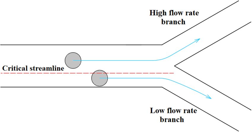
www.nature.com/scientificreports/

                                  Figure 4.  Comparison of simulation and experimental results of Morijiri et al.18 at the rotational speed of
                                  750 rpm. (a) Simulated trajectories of two particles with different sizes and densities (red: silica beads, and blue:
                                  polystyrene beads). (b) Recovery rates obtained by the numerical methods are compared with the experiments.

                                  fields were determined by solving the governing equations of fluid flow. Afterward, to obtain the trajectories of
                                  particles, Newton’s second law of motion was applied to the particles by the Lagrangian approach.
                                      As the first step of the numerical investigation, simulation results of a centrifugal microfluidic separator were
                                  compared with experiments conducted by Morijiri et al.18. Figure 4a shows this Lab-on-a-CD device and the
                                  simulated trajectories of two different-sized silica and polystyrene particles at the rotational speed of 750 rpm.
                                  Particles are entered through inlet 1, and the sheath flow of inlet 2 focuses them onto the upper sidewall in the
                                  pinched segment. Particles are arranged on different streamlines based on their sizes and then are sorted by
                                  centrifugal force based on size and density. According to the simulations, all the silica beads (ρ = 2.0 g cm−3,
                                  d = 5 μm) leave the device through outlet 5, and the polystyrene beads (ρ = 1.05 g cm−3, d = 3 μm) are collected
                                  from outlets 10–12. Figure 4b compares the recovery rates of simulation results with that of the experiment. As
                                  is evident from this figure, numerical simulations are in good agreement with experiments.

Scientific Reports |   (2021) 11:1939 |                https://doi.org/10.1038/s41598-021-81661-2                                                     7

                                                                                                                                                 Vol.:(0123456789)
www.nature.com/scientificreports/
Fluid viscosity (µ) 1.002 × 10⁻³ Nsm−2
Fluid density (ρ) 100 kg m−3
Particle density (ρp) 1050 kg m−3
Magnet’s strength ( B) 0.34 T
Relative permeability of magnet 3.6
Table 1. Physical properties considered for simulations.
To ensure that the results are independent of the grid size, a grid independence study was conducted. Several
grid densities were constructed, and velocity fields and particle recovery rates were investigated. It was found
that an unstructured tetrahedral grid with a mean characteristic size of 23 μm is proper for the passive design
of separator. Also, a similar grid with a mean characteristic size of 36 μm was found proper for the fluid domain
of hybrid design. A summary of the mesh independence study is presented in Table S1 and Figures S4 and S5.
Moreover, Figures S6 and S7 show the selected grids for the passive design and the end part of the hybrid design,
respectively.
To exploit the best effect of CEA microchannel and bifurcation phenomena on particle separation, several
microchannel designs and disk rotational speeds were examined. Also, for the special case of the hybrid plan, the
design of the magnetic region and magnet’s strength were optimized to achieve the best performance of separa-
tion. MCF-7 breast cancer cells and mouse fibroblast L929 cells were chosen as the target and non-target cells,
respectively. Also, the cell ratio in the sample was assumed to be 1:10 as MCF-7s/L929s. Based on experimental
measurements, the average size of MCF-7 and L929 cells were considered 23 µm and 14 µm, respectively. Besides,
physical properties of the sample and magnet are presented in Table 1. To evaluate the performance of separa-
tion device, recovery rate and purity are introduced as two determinant parameters. Recovery rate is defined as
the ratio of the number of a specific cell collected from a chamber over the whole number of the same cell. Also,
purity is defined as the ratio of the number of a specific cell recovered from a chamber over the whole number
of cells existing in the same chamber.
Simulation results of the passive design of separator show that a CEA microchannel with 20 contrac-
tion–expansion steps which is connected to a bifurcation region would be able to conduct two different-sized
particles (14 and 23 µm) in approximately two distinct pathways. This ability can also be guaranteed for relatively
a wide range of rotational speeds (900–3000 rpm). However, the best performance of the separation device could
be achieved at 2400 rpm. In this rotational speed, 100% of MCF-7s are collected from the target chamber with
a purity of 78%. Figure S8 shows the contour plots of the fluid velocity for the passive design at disk rotational
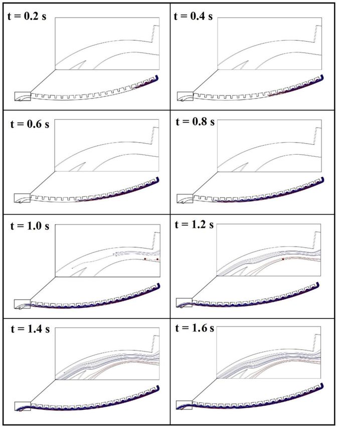
speed of 2400 rpm. Figure 5 depicts the trajectories of particles at different times with intervals of 0.2 s. In this
figure, trajectories of the target particles (MCF-7 cells) and non-target particles (L929 cells) are shown in red
and blue lines, respectively. As illustrated in this figure, after successive flow contractions and expansions, the
target particles are deflected towards the outer streamlines (respect to the center of rotation). Subsequently, these
particles pass underneath the critical streamline and are entered into the low-flow-rate branch. On the other
hand, non-target particles are located on inner streamlines that pass above the critical streamline and conducted
inside the high-flow-rate branch. Therefore, the target particles can be enriched through a contraction–expan-
sion array and bifurcation phenomena.
In the hybrid design, a CEA microchannel similar to that of passive design is employed to take apart the direc-
tions of two different-sized particles. However, the target particles are assumed to be labeled with paramagnetic
nanoparticles and experience a magnetic field at the end part of the separation device. In this way, the target
particles are attracted to the target chamber through the magnetic force, while the non-target particles move
along their paths towards the non-target chamber.
To avoid the huge memory usage of hybrid plan simulations, just the magnetic region of this plan was inves-
tigated and the boundary conditions at the inlet of this region were considered as those which calculated for
this section of passive plan. To study the effect of disk rotational speed on separation efficiency, a wide range of
rotational speed (900–3000 rpm) was considered. As an example, the trajectories of particles at the rotational
speed of 2100 rpm is depicted in Fig. 6 at different times with intervals of 0.2 s. In this situation, 70% of the target
cells are collected from the target chamber with purity of close to 100%. Simulation results predict that the best
performance of the hybrid plan can be achieved at 1500 rpm so that 100% of the target cells are recovered from
the target chamber with 100% purity. Based on simulation results of passive and hybrid devices, we selected
the proper test range of rotational speed for each of them to achieve high recovery rate of target cells and low
recovery rate of non-target cells, simultaneously.
Experimental results. MCF-7 cells as target cancer cells, and L929 mouse fibroblasts as non-target cells
were cultured at 37 °C, 5% CO2, and 95% relative humidity. Figure 7 shows size distribution of MCF-7 and L929
cells with mean diameters of 23 µm and 14 µm, respectively. The target cells were stained with DAPI fluorescent
dye and then rinsed with Phosphate-buffered saline (PBS) solution. The final sample was prepared by suspend-
ing the cells in 15 ml PBS including 2% fetal bovine serum (FBS). Meanwhile, 4% glutaraldehyde was added into
Scientific Reports | (2021) 11:1939 | https://doi.org/10.1038/s41598-021-81661-2 8
Vol:.(1234567890)www.nature.com/scientificreports/
Figure 5. Simulated trajectories of 23 µm-particles (as MCF-7s) in red lines and 14 µm-particles (as L929s) in
blue lines by using passive design of separator at the rotational speed of 2400 rpm.
sample to prevent cell aggregation. It should be recalled that to employ the hybrid plan, magnetite nanoparticles
were bound to the target cells using the method described previously, and glutaraldehyde was not used in sample
due to the its adverse effect on antigen–antibody interactions.
Scientific Reports | (2021) 11:1939 | https://doi.org/10.1038/s41598-021-81661-2 9
Vol.:(0123456789)www.nature.com/scientificreports/
Figure 6. Simulated trajectories of 23 µm-particles (as MCF-7s) in red lines and 14 µm-particles (as L929s) in
blue lines at the end of the hybrid design of separator at the rotational speed of 2100 rpm.
Figure 7. Size distribution of target and non-target cells. (a) MCF-7 cells with a mean diameter of 23 µm and
(b) L929 cells with a mean diameter of 14 µm.
Scientific Reports | (2021) 11:1939 | https://doi.org/10.1038/s41598-021-81661-2 10
Vol:.(1234567890)www.nature.com/scientificreports/
Figure 8. Fluorescent images of MCF-7 cells captured by the passive centrifugal separator at the rotational
speed of 2100 rpm. (a) Target chamber. (b) Non-target chamber.
Before using the separation device, microchannels were filled with PBS to reduce the effects of surface ten-
sion. The spike sample of MCF7 and L-929 cells was prepared for the tests with a cell ratio of 1:10 and the overall
cell count of ~ 5000 cells per microliter of PBS buffer. After the injection of 2 µl of the spike sample in the inlet
chamber, each test was run for one minute and the tests were replicated 5 times for each intended disk rotational
speed. At the end of each trial, the outlet chambers were drained separately into two petri dishes, where their
contents were analyzed to count the cell numbers by the method previously discussed. It should be mentioned
that at the end of each test, microchannels were rinsed with PBS and trypsin to ensure that all the cells are
detached from the channel surfaces.
In order to experimentally investigate the passive design of separation device, the device was tested at three
different rotational speeds of 2100, 2400, and 2700 rpm. Figure 8 shows the fluorescent images of MCF-7 cells
captured in target and non-target chambers at the rotational speed of 2100 rpm. To summarize all the results
obtained from the passive design of separator, Fig. 9 represents both numerical and experimental recovery rates
of MCF-7 and L929 cells from the target chamber. Based on experiments, the maximum recovery rate of target
cells in the passive design of separator can be achieved at the rotational speed of 2100 rpm. This result is relatively
consistent with the results observed from simulation, which predicted the best performance of the passive plan at
the rotational speed of 2400 rpm. In the rotational speed of 2100 rpm, 76% of MCF-7 cells were recovered from
target chamber. Nevertheless, about 40% of L929 cells were also collected into this chamber. Considering the
trends of simulation results suggests that testing the device at lower rotational speeds would cause an increase
in the recovery rate of non-target cells that is not desirable as it adversely affects the target cell purity.
Finally, hybrid design of separation device was tested experimentally. To this end, device performance was
evaluated at three different rotational speeds of 1200, 1500, and 1800 rpm. The respective recovery rates of MCF-7
and L929 cells from the target chamber are presented in Fig. 10. Meanwhile, the simulation results of the hybrid
Scientific Reports | (2021) 11:1939 | https://doi.org/10.1038/s41598-021-81661-2 11
Vol.:(0123456789)www.nature.com/scientificreports/
Figure 9. Numerical and experimental recovery rates of MCF-7 and L929 cells from the target chamber of the
passive design of separator.
Figure 10. Numerical and experimental recovery rates of MCF-7 and L929 cells from the target chamber of the
hybrid design of separator.
plan are illustrated and compared with experimental data in this figure. It is obvious that experimental and
numerical results are in good agreement. Furthermore, the maximum recovery rate of target cells is predicted at
the rotational speed of 1200 rpm, where 85% of MCF-7 and 18% of L929 cells are collected into the target cham-
ber. This result conforms to the findings from simulations at 1200 rpm, where all the target cells were recovered
into the target chamber with 100% purity.
A comparison between two studied plans of separation device shows that the hybrid design of separator is
able to separate more percentage of the target cells with higher purity. On the other hand, the passive design of
separator is easily operated without the time-consuming process of cell labeling and imposing additional costs.
Consequently, there is a tradeoff between accuracy and easiness of separation method to choose the desired
design of separator.
Conclusion
In this study, two passive and hybrid centrifugal designs of a separator device were investigated for enrichment of
the rare cancer cells. The passive design utilizes the advantages of CEA microchannel and bifurcation to separate
cancer cells from the population of non-target cells. However, in hybrid design, the CEA microchannel is directly
connected to a magnetic region, where a magnetophoretic technique is utilized to separate the magnetically
labelled target cells from the non-target ones. Numerical simulations were carried out to determine the optimized
geometries and disk rotational speeds for both passive and hybrid designs. Afterward, the optimized designs
were fabricated through CNC micromachining of plexiglass plates and tested to separate MCF-7 cells as target
cells from the population of mouse L929 cells as non-target cells. To employ the hybrid plan, magnetite nano-
particles were bound to MCF-7 cells through the specific EP-CAM antibodies. Experiment results indicated that
by utilizing the passive design of the separator at 2100 rpm, 76% of MCF-7 cells were recovered from the target
chamber while 40% of L929 cells were also collected from this chamber. Additionally, the hybrid design was able
Scientific Reports | (2021) 11:1939 | https://doi.org/10.1038/s41598-021-81661-2 12
Vol:.(1234567890)www.nature.com/scientificreports/
to collect 85% of MCF-7 cells and only 18% of L929 into the target chamber at the rotational speed of 1200 rpm.
As is evident from the experiments conducted in the reported rotational speeds, the hybrid design of separator
is able to simultaneously offer a higher recovery rate and purity for cell enrichment at the optimal rotational
speeds suggested by the simulation results. Nevertheless, the passive design can be a convenient choice for rapid
and admissible enrichment of cancer cells with no need for grueling and time-consuming process of cell labeling.
Received: 28 September 2020; Accepted: 8 January 2021
References
1. Antfolk, M., Kim, S. H., Koizumi, S., Fujii, T. & Laurell, T. Label-free single-cell separation and imaging of cancer cells using an
integrated microfluidic system. Sci. Rep. 7, 46507 (2017).
2. Li, X., Chen, Y. & Li, P. C. A simple and fast microfluidic approach of same-single-cell analysis (SASCA) for the study of multidrug
resistance modulation in cancer cells. Lab Chip 11, 1378–1384 (2011).
3. Sajeesh, P. & Sen, A. K. Particle separation and sorting in microfluidic devices: A review. Microfluid. Nanofluid. 17, 1–52 (2014).
4. Yamada, M., Nakashima, M. & Seki, M. Pinched flow fractionation: continuous size separation of particles utilizing a laminar flow
profile in a pinched microchannel. Anal. chem. 76, 5465–5471 (2004).
5. Huang, L. R., Cox, E. C., Austin, R. H. & Sturm, J. C. Continuous particle separation through deterministic lateral displacement.
Science 304, 987–990 (2004).
6. Di Carlo, D., Edd, J. F., Irimia, D., Tompkins, R. G. & Toner, M. Equilibrium separation and filtration of particles using differential
inertial focusing. Anal. chem. 80, 2204–2211 (2008).
7. Yen, R. & Fung, Y. Effect of velocity distribution on red cell distribution in capillary blood vessels. Am. J. Physiol. Heart Circ. 235,
H251–H257 (1978).
8. Breadmore, M. C. et al. Recent advances in enhancing the sensitivity of electrophoresis and electrochromatography in capillaries
and microchips (2012–2014). Electrophoresis 36, 36–61 (2015).
9. Shamloo, A. & Kamali, A. Numerical analysis of a dielectrophoresis field-flow fractionation device for the separation of multiple
cell types. J. Sep. Sci. 40, 4067–4075 (2017).
10. Liu, C., Stakenborg, T., Peeters, S. & Lagae, L. Cell manipulation with magnetic particles toward microfluidic cytometry. J. Appl.
Phys. 105, 102014 (2009).
11. Shamloo, A. & Parast, F. Y. Simulation of blood particle separation in a trapezoidal microfluidic device by acoustic force. IEEE
Trans. Electron Devices 66, 1495–1503 (2019).
12. Jonáš, A. & Zemanek, P. Light at work: The use of optical forces for particle manipulation, sorting, and analysis. Electrophoresis
29, 4813–4851 (2008).
13. Yan, S., Zhang, J., Yuan, D. & Li, W. Hybrid microfluidics combined with active and passive approaches for continuous cell separa-
tion. Electrophoresis 38, 238–249 (2017).
14. Gorkin, R. et al. Centrifugal microfluidics for biomedical applications. Lab Chip 10, 1758–1773 (2010).
15. Wei, X. et al. Multiplexed instrument-free bar-chart spinchip integrated with nanoparticle-mediated magnetic aptasensors for
visual quantitative detection of multiple pathogens. Anal. chem. 90, 9888–9896 (2018).
16. Naghdloo, A., Ghazimirsaeed, E. & Shamloo, A. Numerical simulation of mixing and heat transfer in an integrated centrifugal
microfluidic system for nested-PCR amplification and gene detection. Sens. Actuators, B Chem. 283, 831–841 (2019).
17. Dou, M., Sanjay, S. T., Dominguez, D. C., Zhan, S. & Li, X. A paper/polymer hybrid CD-like microfluidic SpinChip integrated with
DNA-functionalized graphene oxide nanosensors for multiplex qLAMP detection. Chem. Commun. 53, 10886–10889 (2017).
18. Morijiri, T., Sunahiro, S., Senaha, M., Yamada, M. & Seki, M. Sedimentation pinched-flow fractionation for size-and density-based
particle sorting in microchannels. Microfluid Nanofluidics 11, 105–110 (2011).
19. Yeo, J. C. et al. Label-free extraction of extracellular vesicles using centrifugal microfluidics. Biomicrofluidics 12, 024103 (2018).
20. Lee, A. et al. All-in-one centrifugal microfluidic device for size-selective circulating tumor cell isolation with high purity. Anal.
Chem. 86, 11349–11356 (2014).
21. Kirby, D. et al. Centrifugo-magnetophoretic particle separation. Microfluid. Nanofluid. 13, 899–908 (2012).
22. Glynn, M. et al. Centrifugo-magnetophoretic purification of CD4+ cells from whole blood toward future HIV/AIDS point-of-care
applications. J. Lab. Autom. 19, 285–296 (2014).
23. Chen, C.-L. et al. Separation and detection of rare cells in a microfluidic disk via negative selection. Lab Chip 11, 474–483 (2011).
24. Shamloo, A. & Besanjideh, M. Investigation of a novel microfluidic device for label-free ferrohydrodynamic cell separation on a rotat-
ing Disk (IEEE Trans. Biomed, Eng, 2019).
25. Yang, S., Ündar, A. & Zahn, J. D. A microfluidic device for continuous, real time blood plasma separation. Lab Chip 6, 871–880
(2006).
26. Geng, Z., Zhang, L., Ju, Y., Wang, W. & Li, Z. in 15 International Conference on Miniaturized Systems for Chemistry and Life Sciences
2011, Washington. 224–226.
27. Zhang, J. et al. Fundamentals and applications of inertial microfluidics: A review. Lab Chip 16, 10–34 (2016).
28. Di Carlo, D., Irimia, D., Tompkins, R. G. & Toner, M. Continuous inertial focusing, ordering, and separation of particles in micro-
channels. PNAS 104, 18892–18897 (2007).
29. Bhagat, A. A. S., Kuntaegowdanahalli, S. S. & Papautsky, I. Continuous particle separation in spiral microchannels using dean
flows and differential migration. Lab. Chip 8, 1906–1914 (2008).
30. Kuntaegowdanahalli, S. S., Bhagat, A. A. S., Kumar, G. & Papautsky, I. Inertial microfluidics for continuous particle separation in
spiral microchannels. Lab Chip 9, 2973–2980 (2009).
31. Lee, M. G., Choi, S. & Park, J.-K. Inertial separation in a contraction–expansion array microchannel. J. Chromatogr. A 1218,
4138–4143 (2011).
32. Shamloo, A., Abdorahimzadeh, S. & Nasiri, R. Exploring contraction–expansion inertial microfluidic-based particle separation
devices integrated with curved channels. AIChE J. 65, e16741 (2019).
33. Lee, M. G. et al. Inertial blood plasma separation in a contraction–expansion array microchannel. Appl. Phys. Lett. 98, 253702
(2011).
34. Hejazian, M., Li, W. & Nguyen, N.-T. Lab on a chip for continuous-flow magnetic cell separation. Lab Chip 15, 959–970 (2015).
35. Madadelahi, M., Acosta-Soto, L. F., Hosseini, S., Martinez-Chapa, S. O. & Madou, M. J. Mathematical modeling and computational
analysis of centrifugal microfluidic platforms: A review. Lab Chip 20, 1318–1357 (2020).
36. Shen, F., Li, X. & Li, P. C. Study of flow behaviors on single-cell manipulation and shear stress reduction in microfluidic chips using
computational fluid dynamics simulations. Biomicrofluidics 8, 014109 (2014).
37. Schiller, L. Über die grundlegenden Berechnungen bei der Schwerkraftaufbereitung. Z. Vereines Deutscher Inge. 77, 318–321 (1933).
Scientific Reports | (2021) 11:1939 | https://doi.org/10.1038/s41598-021-81661-2 13
Vol.:(0123456789)www.nature.com/scientificreports/
38. Asmolov, E. S. The inertial lift on a spherical particle in a plane Poiseuille flow at large channel Reynolds number. J. Fluid Mech.
381, 63–87 (1999).
39. Pamme, N. & Manz, A. On-chip free-flow magnetophoresis: Continuous flow separation of magnetic particles and agglomerates.
Anal. Chem. 76, 7250–7256 (2004).
40. Ogilvie, I. et al. Reduction of surface roughness for optical quality microfluidic devices in PMMA and COC. J. Micromech. Microeng.
20, 065016 (2010).
41. Morel, A.-L. et al. Sonochemical approach to the synthesis of Fe3O4@ SiO2 core-shell nanoparticles with tunable properties. ACS
Nano 2, 847–856 (2008).
42. Hyeon, T. Chemical synthesis of magnetic nanoparticles. Chem. Commun. 8, 927–934 (2003).
Author contributions
A.S. designed the experiments, managed the project, analyzed the data and wrote the paper, A.N., ran the simu-
lations and experiments, analyzed the data and wrote the paper. M.B. analyzed the data and wrote the paper.
Competing interests
The authors declare no competing interests.
Additional information
Supplementary Information The online version contains supplementary material available at https://doi.
org/10.1038/s41598-021-81661-2.
Correspondence and requests for materials should be addressed to A.S.
Reprints and permissions information is available at www.nature.com/reprints.
Publisher’s note Springer Nature remains neutral with regard to jurisdictional claims in published maps and
institutional affiliations.
Open Access This article is licensed under a Creative Commons Attribution 4.0 International
License, which permits use, sharing, adaptation, distribution and reproduction in any medium or
format, as long as you give appropriate credit to the original author(s) and the source, provide a link to the
Creative Commons licence, and indicate if changes were made. The images or other third party material in this
article are included in the article’s Creative Commons licence, unless indicated otherwise in a credit line to the
material. If material is not included in the article’s Creative Commons licence and your intended use is not
permitted by statutory regulation or exceeds the permitted use, you will need to obtain permission directly from
the copyright holder. To view a copy of this licence, visit http://creativecommons.org/licenses/by/4.0/.
© The Author(s) 2021
Scientific Reports | (2021) 11:1939 | https://doi.org/10.1038/s41598-021-81661-2 14
Vol:.(1234567890)You can also read