Network Portable IR Speed Dome - User Manual - Videovision
←
→
Page content transcription
If your browser does not render page correctly, please read the page content below

User Manual of Network Portable IR Speed Dome

Network Portable IR Speed Dome

                                                       User Manual

                            0
User Manual of Network Portable IR Speed Dome

User Manual
COPYRIGHT © 2019 Hangzhou Hikvision Digital Technology Co., Ltd.
ALL RIGHTS RESERVED.
Any and all information, including, among others, wordings, pictures, graphs are the
properties of Hangzhou Hikvision Digital Technology Co., Ltd. or its subsidiaries
(hereinafter referred to be “Hikvision”). This user manual (hereinafter referred to be
“the Manual”) cannot be reproduced, changed, translated, or distributed, partially or
wholly, by any means, without the prior written permission of Hikvision. Unless
otherwise stipulated, Hikvision does not make any warranties, guarantees or
representations, express or implied, regarding to the Manual.
About this Manual
This Manual is applicable to Network Portable IR Speed Dome.
The Manual includes instructions for using and managing the product. Pictures, charts,
images and all other information hereinafter are for description and explanation only.
The information contained in the Manual is subject to change, without notice, due to
firmware updates or other reasons. Please find the latest version in the company
website (http://overseas.hikvision.com/en/).
Please use this user manual under the guidance of professionals.
Trademarks Acknowledgement
              and other Hikvision’s trademarks and logos are the properties of
Hikvision in various jurisdictions. Other trademarks and logos mentioned below are
the properties of their respective owners.
Legal Disclaimer
TO THE MAXIMUM EXTENT PERMITTED BY APPLICABLE LAW, THE PRODUCT
DESCRIBED, WITH ITS HARDWARE, SOFTWARE AND FIRMWARE, IS PROVIDED “AS IS”,
WITH ALL FAULTS AND ERRORS, AND HIKVISION MAKES NO WARRANTIES, EXPRESS
OR IMPLIED, INCLUDING WITHOUT LIMITATION, MERCHANTABILITY, SATISFACTORY
QUALITY, FITNESS FOR A PARTICULAR PURPOSE, AND NON-INFRINGEMENT OF THIRD
PARTY. IN NO EVENT WILL HIKVISION, ITS DIRECTORS, OFFICERS, EMPLOYEES, OR
AGENTS BE LIABLE TO YOU FOR ANY SPECIAL, CONSEQUENTIAL, INCIDENTAL, OR
INDIRECT DAMAGES, INCLUDING, AMONG OTHERS, DAMAGES FOR LOSS OF BUSINESS
PROFITS, BUSINESS INTERRUPTION, OR LOSS OF DATA OR DOCUMENTATION, IN
CONNECTION WITH THE USE OF THIS PRODUCT, EVEN IF HIKVISION HAS BEEN
ADVISED OF THE POSSIBILITY OF SUCH DAMAGES.
REGARDING TO THE PRODUCT WITH INTERNET ACCESS, THE USE OF PRODUCT SHALL
BE WHOLLY AT YOUR OWN RISKS. HIKVISION SHALL NOT TAKE ANY RESPONSIBILITES
FOR ABNORMAL OPERATION, PRIVACY LEAKAGE OR OTHER DAMAGES RESULTING
FROM CYBER ATTACK, HACKER ATTACK, VIRUS INSPECTION, OR OTHER INTERNET

                                             1
User Manual of Network Portable IR Speed Dome

SECURITY RISKS; HOWEVER, HIKVISION WILL PROVIDE TIMELY TECHNICAL SUPPORT IF
REQUIRED.
SURVEILLANCE LAWS VARY BY JURISDICTION. PLEASE CHECK ALL RELEVANT LAWS IN
YOUR JURISDICTION BEFORE USING THIS PRODUCT IN ORDER TO ENSURE THAT YOUR
USE CONFORMS THE APPLICABLE LAW. HIKVISION SHALL NOT BE LIABLE IN THE EVENT
THAT THIS PRODUCT IS USED WITH ILLEGITIMATE PURPOSES.
IN THE EVENT OF ANY CONFLICTS BETWEEN THIS MANUAL AND THE APPLICABLE LAW,
THE LATER PREVAILS.

                                           2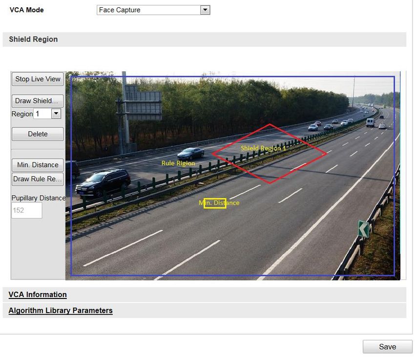
User Manual of Network Portable IR Speed Dome

Regulatory Information
FCC Information
FCC compliance: This equipment has been tested and found to comply with the
limits for a digital device, pursuant to part 15 of the FCC Rules. These limits are
designed to provide reasonable protection against harmful interference when the
equipment is operated in a commercial environment. This equipment generates,
uses, and can radiate radio frequency energy and, if not installed and used in
accordance with the instruction manual, may cause harmful interference to radio
communications. Operation of this equipment in a residential area is likely to cause
harmful interference in which case the user will be required to correct the
interference at his own expense.
FCC Conditions
This device complies with part 15 of the FCC Rules. Operation is subject to the
following two conditions:
1. This device may not cause harmful interference.
2. This device must accept any interference received, including interference that may
cause undesired operation.
EU Conformity Statement

                    This product and - if applicable - the supplied accessories too are
                    marked with "CE" and comply therefore with the applicable
                    harmonized European standards listed under the Low Voltage
                    Directive 2015/35/EU, the EMC Directive 2014/30/EU, the RoHS
                    Directive 2011/65/EU.

             2012/19/EU (WEEE directive): Products marked with this symbol
             cannot be disposed of as unsorted municipal waste in the European
             Union. For proper recycling, return this product to your local supplier
             upon the purchase of equivalent new equipment, or dispose of it at
             designated collection points. For more information see:
www.recyclethis.info.

                2006/66/EC (battery directive): This product contains a battery that
                cannot be disposed of as unsorted municipal waste in the European
                Union. See the product documentation for specific battery
                information. The battery is marked with this symbol, which may
include lettering to indicate cadmium (Cd), lead (Pb), or mercury (Hg). For proper
recycling, return the battery to your supplier or to a designated collection point. For
more information, see: www.recyclethis.info.

                                              3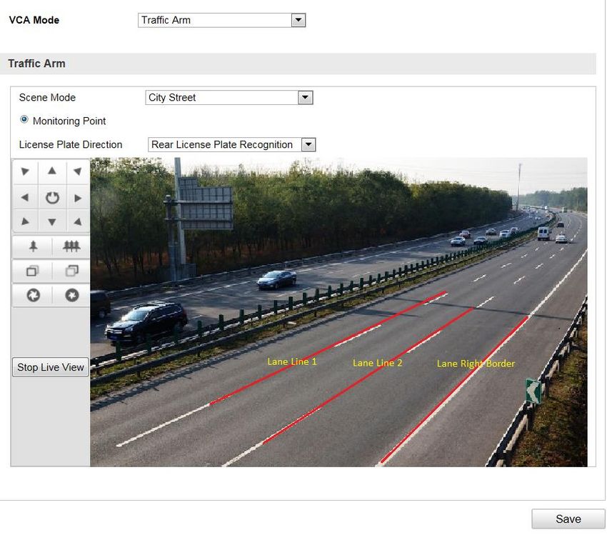
User Manual of Network Portable IR Speed Dome
Safety Instruction
These instructions are intended to ensure that the user can use the product correctly
to avoid danger or property loss.
The precaution measure is divided into ‘Warnings’ and ‘Cautions’:
Warnings: Serious injury or death may be caused if any of these warnings are
neglected.
Cautions: Injury or equipment damage may be caused if any of these cautions are
neglected.
Warnings Follow these safeguards to Cautions Follow these precautions to
prevent serious injury or death. prevent potential injury or material
damage.
Warnings:
Please adopt the power adapter which can meet the safety extra low voltage (SELV)
standard. The power consumption cannot be less than the required value.
Do not connect several devices to one power adapter as an adapter overload may
cause over-heating and can be a fire hazard.
When the product is installed on a wall or ceiling, the device should be firmly fixed.
To reduce the risk of fire or electrical shock, do not expose the indoor used product
to rain or moisture.
This installation should be made by a qualified service person and should conform
to all the local codes.
Please install blackouts equipment into the power supply circuit for convenient
supply interruption.
If the product does not work properly, please contact your dealer or the nearest
service center. Never attempt to disassemble the product yourself. (We shall not
assume any responsibility for problems caused by unauthorized repair or
maintenance.)
4
User Manual of Network Portable IR Speed Dome
Cautions:
Make sure the power supply voltage is correct before using the product.
Do not drop the product or subject it to physical shock. Do not install the product
on vibratory surface or places.
Do not expose it to high electromagnetic radiating environment.
Do not aim the lens at the strong light such as sun or incandescent lamp. The strong
light can cause fatal damage to the product.
The sensor may be burned out by a laser beam, so when any laser equipment is
being used, make sure that the surface of the sensor not be exposed to the laser
beam.
For working temperature, please refer to the specification manual for details.
To avoid heat accumulation, good ventilation is required for a proper operating
environment.
While shipping, the product should be packed in its original packing.
Please use the provided glove when open up the product cover. Do not touch the
product cover with fingers directly, because the acidic sweat of the fingers may
erode the surface coating of the product cover.
Please use a soft and dry cloth when clean inside and outside surfaces of the
product cover. Do not use alkaline detergents.
Improper use or replacement of the battery may result in hazard of explosion.
Please use the manufacturer recommended battery type.
Notes:
For the camera supports IR, you are required to pay attention to the following
precautions to prevent IR reflection:
Dust or grease on the dome cover will cause IR reflection. Please do not remove
the dome cover film until the installation is finished. If there is dust or grease on
the dome cover, clean the dome cover with clean soft cloth and isopropyl alcohol.
Make certain the installation location does not have reflective surfaces of objects
too close to the camera. The IR light from the camera may reflect back into the lens
causing reflection.
The foam ring around the lens must be seated flush against the inner surface of
the bubble to isolate the lens from the IR LEDS. Fasten the dome cover to camera
body so that the foam ring and the dome cover are attached seamlessly.
5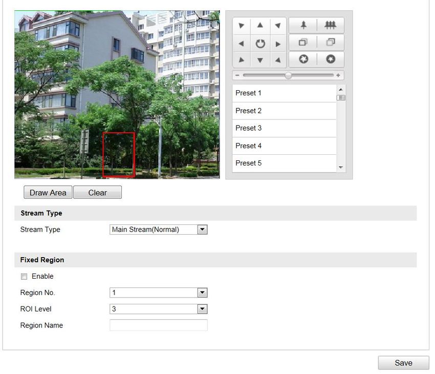
User Manual of Network Portable IR Speed Dome

                                            Table of Contents
CHAPTER 1 INTRODUCTION .................................................................................................... 9

   1.1        PRODUCT INTRODUCTION .................................................................................................... 9
   1.2        KEY FEATURE ..................................................................................................................... 9

CHAPTER 2 NETWORK CONNECTION ................................................................................. 10

   2.1        SET SPEED DOME OVER LAN............................................................................................. 10
   2.2        SET SPEED DOME OVER WAN ............................................................................................ 11
      2.2.1        Connect via Wi-Fi AP.................................................................................................. 11
      2.2.2        Connect with Static IP Address .................................................................................... 11
      2.2.3        Set Dialing .................................................................................................................. 12

CHAPTER 3 ACTIVATION......................................................................................................... 13

   3.1        ACTIVATE VIA WEB BROWSER............................................................................................ 13
   3.2        ACTIVATE VIA SADP SOFTWARE ........................................................................................ 14

CHAPTER 4 LOGIN .................................................................................................................... 15

CHAPTER 5 LIVE VIEW ............................................................................................................ 16

   5.1        POWER-UP ACTION ............................................................................................................ 16
   5.2        LIVE VIEW INTERFACE INTRODUCTION ............................................................................... 16
   5.3        START LIVE VIEW .............................................................................................................. 17
   5.4        RECORD AND CAPTURE IMAGES MANUALLY ...................................................................... 19
   5.5        PTZ CONTROL .................................................................................................................. 19
      5.5.1        PTZ Control Panel ...................................................................................................... 19
      5.5.2        Set/Call a Preset ......................................................................................................... 20
      5.5.3        Set/Call a Patrol ......................................................................................................... 21
      5.5.4        Set/Call a Pattern........................................................................................................ 22
   5.6        CONFIGURE LIVE VIEW PARAMETERS ................................................................................ 23

CHAPTER 6 PLAYBACK............................................................................................................ 24

   6.1        PLAY BACK VIDEO FILES ................................................................................................... 24
   6.2        DOWNLOAD VIDEO FILES .................................................................................................. 25

CHAPTER 7 PICTURE................................................................................................................ 27

CHAPTER 8 CAPTURE .............................................................................................................. 28

CHAPTER 9 SPEED DOME CONFIGURATION ...................................................................... 29

   9.1        LOCAL PARAMETERS CONFIGURATION ............................................................................... 29
   9.2        SYSTEM CONFIGURATION .................................................................................................. 30
      9.2.1        View Device Information ............................................................................................. 30
      9.2.2        Configure Time ........................................................................................................... 31
      9.2.3        Maintenance ............................................................................................................... 32
      9.2.4        Configure RS-232........................................................................................................ 34
      9.2.5        Configure RS-485........................................................................................................ 35
                                                                        6
User Manual of Network Portable IR Speed Dome

  9.2.6       Configure DST (Daylight Saving Time) ........................................................................ 36
  9.2.7       Service ........................................................................................................................ 36
9.3       NETWORK CONFIGURATION ............................................................................................... 37
  9.3.1       Connect to Access Platform ......................................................................................... 37
  9.3.2       Configure Port ............................................................................................................ 37
  9.3.3       Configure QoS ............................................................................................................ 38
  9.3.4       Configure Email .......................................................................................................... 38
  9.3.5       Connect to Hik-Connect .............................................................................................. 40
9.4       NETWORK CONNECTION CONFIGURATION .......................................................................... 41
  9.4.1       Configure TCP/IP ....................................................................................................... 41
  9.4.2       Configure Wi-Fi .......................................................................................................... 42
  9.4.3       Configure Wi-Fi Hotspot ............................................................................................. 43
  9.4.4       Configure Location ..................................................................................................... 44
  9.4.5       Configure Dialing ....................................................................................................... 45
  9.4.6       Configure Bluetooth .................................................................................................... 47
9.5       VIDEO AND AUDIO CONFIGURATION ................................................................................... 47
  9.5.1       Configure Video .......................................................................................................... 47
  9.5.2       Configure Audio .......................................................................................................... 49
  9.5.3       Configuring ROI ......................................................................................................... 49
9.6       PTZ CONFIGURATION ........................................................................................................ 50
  9.6.4       Configure Basic PTZ Parameters ................................................................................ 50
  9.6.5       Configure Park Actions ............................................................................................... 51
  9.6.6       Configure Scheduled Tasks .......................................................................................... 52
  9.6.7       Clear PTZ Configurations ........................................................................................... 54
9.7       IMAGE CONFIGURATION ..................................................................................................... 55
  9.7.1       Configure Display ....................................................................................................... 55
  9.7.2       Configure OSD ........................................................................................................... 60
  9.7.3       Configure Text Overlay................................................................................................ 61
9.8       SECURITY PARAMETERS CONFIGURATION .......................................................................... 62
  9.8.1       Manage User Accounts................................................................................................ 62
  9.8.2       Configure RTSP Authentication ................................................................................... 64
  9.8.3       Configure IP Address Filter ......................................................................................... 65
9.9       ALARMS CONFIGURATION .................................................................................................. 66
  9.9.1       Configure Alarm Input ................................................................................................ 66
  9.9.2       Configure Alarm Output .............................................................................................. 68
  9.9.3       Handle Exception ........................................................................................................ 69
9.10      STORAGE CONFIGURATION ................................................................................................ 70
  9.10.1      Configure Recording Schedule..................................................................................... 70
  9.10.2      Manage Storage .......................................................................................................... 72
  9.10.3      Configure NAS ............................................................................................................ 73
  9.10.4      Configure Snapshot ..................................................................................................... 74
9.11      CAPTURE CONFIGURATION ................................................................................................ 76
  9.11.1      Configure Camera Position Parameters ...................................................................... 76
  9.11.2      Configure Image ......................................................................................................... 76

                                                                    7
User Manual of Network Portable IR Speed Dome

  9.11.3    Configure Blacklist...................................................................................................... 78
  9.11.4    Configure Vehicle Counting ......................................................................................... 80
  9.11.5    Configure Vehicle Characteristics................................................................................ 80
9.12   VCA CONFIGURATION ....................................................................................................... 81
  9.12.1    Configure Traffic Arm ................................................................................................. 81
  9.12.2    Configure Face Capture .............................................................................................. 82
9.13   STATUS ............................................................................................................................. 83

                                                                  8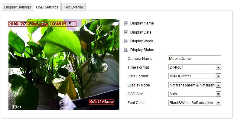
User Manual of Network Portable IR Speed Dome
Chapter 1 Introduction
1.1 Product Introduction
Embedded with 4G, Wi-Fi, GPS module, LPR (License Plate Recognition) and face
capture algorithm, and deep learning algorithm, DS-MH6171I-A(S) network portable
IR speed dome (hereinafter referred to as speed dome) is widely used in temporary
events surveillance and license plate recognition for mobile scenes, e.g. parade, strike,
outdoor concert, law enforcement, and onboard monitoring, etc.
1.2 Key Feature
Video
1/2.8" progressive scan CMOS; 1920 × 1080/1280 × 720 resolution
H.265/H.264+/H.264 video compression
30× optical zoom, 16× digital zoom
HLC/BLC/3D DNR/Defog/EIS
Support up to 80 m IR distance
Storage
Dual built-in SD/SDXC card slot, up to 128 GB for each memory card
Communication Module
Support 4G module; 802.11b/g/n Wi-Fi; GPS positioning module; Bluetooth 4.0
Usability
Support quick installation with the magnetic base and the tripod bracket
Support Wi-Fi AP, which allows to connect the phone to the camera directly and
control the camera conveniently
Pluggable battery for continuous work, up to six hours
Replaceable battery for sustainable work
True 360° endless pan and -15° to 90° (auto-flip) tilt movement range for PTZ
Smart Function
Support LPR and blacklist
Face capture
9User Manual of Network Portable IR Speed Dome
Chapter 2 Network Connection
Notes:
You shall acknowledge that the use of the product with Internet access might be
under network security risks. For avoidance of any network attacks and
information leakage, please strengthen your own protection. If the product does
not work properly, please contact with your dealer or the nearest service center.
To ensure the network security of the speed dome, we recommend you to have
the speed dome assessed and maintained termly. You can contact us if you need
such service.
2.1 Set Speed Dome over LAN
To view and configure the speed dome over LAN, you need to connect the speed dome
in the same subnet with your computer, and install the SADP or client software to
search and modify the IP address of the speed dome. You can refer to Chapter 3.2
Activate via SADP Software for IP address modification.
You can directly connect the speed dome to the computer with a network cable, or via
a switch or a router.
Network Cable
Figure 2-1 Direct Connection
Network
Cable
Speed Dome Switch or Router
PC
Figure 2-2 Connection via Switch or Router
10User Manual of Network Portable IR Speed Dome
2.2 Set Speed Dome over WAN
This section explains how to connect the speed dome to WAN with a static or dynamic
IP address.
2.2.1 Connect via Wi-Fi AP
You can connect the speed dome to your PC via Wi-Fi AP (Access Point) network and
transmit the data via the Wi-Fi.
Steps:
1. Search the Wi-Fi with your PC or phone that support Wi-Fi function.
2. Connect the Wi-Fi of the hot spot of the speed dome.
Note:
The default Wi-Fi name is Dome_xxxxxx (Serial No.), and the default password is
abcd1234.
3. Visit the speed dome via web browser or client software.
Notes:
If multiple speed domes are connected in the internet, please edit the IP
address of speed dome in case of the IP address conflict.
For further information about Wi-Fi AP parameters configuration, refer to
Chapter 9.4.2 Configure Wi-Fi.
GPS
Management Center
Intelligent Video
3/4G Service
Management
System
Mobile Client
Portable Speed Dome
Tablet PC
Figure 2-3 Access Speed Dome via Wi-Fi AP
2.2.2 Connect with Static IP Address
Before you start:
Apply a static IP address from an ISP (Internet Service Provider). With the static IP
address, you can connect the speed dome via a router or connect it to WAN directly.
Connect Speed Dome via a Router
Steps:
11User Manual of Network Portable IR Speed Dome
1. Connect the speed dome to the router.
2. Assign a LAN IP address, subnet mask, and gateway. Refer to Chapter 9.4.1
Configure TCP/IP for detailed IP address configuration of the speed dome.
3. Save the static IP in the router.
4. Set port mapping, e.g., 80, 8000, and 554 ports. The steps for port mapping vary
depending on different routers. Please call the router manufacturer for assistance
with port mapping.
5. Visit the speed dome via web browser or client software over the internet.
Network Network Network
Cable Cable Cable
Internet
Router with Static IP
Speed Dome
PC
Figure 2-4 Access the Speed Dome via Router with Static IP Address
Connect Speed Dome with Static IP Address Directly
You can also save the static IP address in the speed dome and directly connect it to the
internet without a router. Refer to Chapter 9.4.1 Configure TCP/IP for detailed IP
address configuration of the speed dome.
Network Network
Cable Cable
Internet
Speed Dome
PC
Figure 2-5 Access the Speed Dome with Static IP Address Directly
2.2.3 Set Dialing
2 SIM cards can be installed on the speed dome, including main SIM card and slave
SIM card. You can configure the dialing settings for each SIM card.
For detailed information, please refer to Chapter 9.4.5 Configure Dialing.
12User Manual of Network Portable IR Speed Dome
Chapter 3 Activation
You are required to activate the speed dome first by setting a strong password for it
before you can use it.
Activation via web browser, SADP, and client software are supported. In the following
sections, activation via web browser and SADP will be taken as examples. You may
refer to the user manual for the details of activation via client software.
3.1 Activate via Web Browser
Steps:
1. Power on the speed dome, and connect the speed dome to the network.
2. Open the web browser.
3. Input the IP address in the address bar, and press Enter to enter the activation
interface.
Note:
The default IP address of the speed dome is 192.0.0.64.
Figure 3-1 Activation Interface (Web)
4. Create a password.
STRONG PASSWORD RECOMMENDED– We highly recommend you create
a strong password of your own choosing (using a minimum of 8 characters,
including at least three of the following categories: upper case letters,
lower case letters, numbers, and special characters) in order to increase
the security of your product. And we recommend you reset your password
regularly, especially in the high security system, resetting the password
monthly or weekly can better protect your product.
5. Confirm the password.
6. Click OK to activate the speed dome and enter the live view interface.
Note:
13User Manual of Network Portable IR Speed Dome
To activate the speed dome under Wi-Fi AP mode, please refer to Section 2.2.1
Connect via Wi-Fi AP.
3.2 Activate via SADP Software
SADP software is used for detecting the online device, activating the device, and
resetting the password.
Get the SADP software from the supplied disk or the official website, and install the
SADP according to the prompts. Follow the steps to activate the speed dome.
Steps:
1. Run the SADP software to search the online devices.
2. Check the device status from the device list, and select an inactive device.
Figure 3-2 SADP Interface
3. Create a password and input the password in the password field, and confirm the
password.
STRONG PASSWORD RECOMMENDED– We highly recommend you create a
strong password of your own choosing (using a minimum of 8 characters,
including at least three of the following categories: upper case letters, lower
case letters, numbers, and special characters) in order to increase the security
of your product. And we recommend you reset your password regularly,
especially in the high security system, resetting the password monthly or
weekly can better protect your product.
4. Click Activate to activate the speed dome.
5. Change the device IP address to the same subnet with your PC by either modifying
the IP address manually or checking Enable DHCP.
14User Manual of Network Portable IR Speed Dome
Chapter 4 Login
Steps:
1. Open the web browser.
2. Input the IP address in the address bar, and press Enter to enter the login interface.
3. Input User Name and Password.
4. Click Login.
Note:
The IP address gets locked if the admin user performs 7 failed password attempts
(5 attempts for the user/operator).
Figure 4-1 Login Interface
5. Follow the installation prompts to install the plug-in before live view and
managing the speed dome.
Note:
You may have to close the web browser to finish the installation of the plug-in.
6. Reopen the web browser after the installation of the plug-in and repeat the above
steps 2-4 to login.
15User Manual of Network Portable IR Speed Dome
Chapter 5 Live View
5.1 Power-up Action
After power-up, the speed dome will perform self-test actions. It begins with lens
actions and then pan and tilt movement. After the power-up self-test actions, the
information as shown in Figure 5-1 will be displayed on screen for 40 seconds.
The System Information displayed on the screen includes the dome model, address,
protocol, version and other information. The COMMUNICATION refers to the baud rate,
parity, data bit and stop bit of the dome. e.g., “2400, N, 8, 1” indicates the dome is
configured with the baud rate of 2400, no parity, 8 data bits and 1 stop bit.
Model XX-XXXXXX-X
Address 0
Communication 0000,0,0,0
Soft Version V000
Camera Software Ver V000
Language Engl ish
Figure 5-1 Power-up Information
5.2 Live View Interface Introduction
The live view interface allows you to view live video, capture images, realize PTZ
control, set/call presets, and configure video parameters.
Log in to the speed dome to enter the live view interface, or you can click Live View
on the menu bar of the main page to enter the live view interface.
16User Manual of Network Portable IR Speed Dome
Figure 5-2 Live View Page
Menu Bar:
Click each tab to enter Live View, Playback, Picture, Configuration, and Capture
interface respectively.
Live View Window:
Display the live video.
Toolbar:
Operations on the live view interface, e.g., live view, capture, record, audio on/off,
two-way audio, etc.
PTZ Control:
Panning, tilting, focusing, and zooming actions of the speed dome. The lighter, wiper,
one-touch focus, and lens initialization control.
Preset/patrol/pattern:
Set and call the preset/patrol/pattern for the speed dome.
Live View Parameters:
Configure the image size and stream type of the live video.
5.3 Start Live View
In the live view window as shown in Figure 5-3, click on the toolbar to start live
view of the speed dome.
17User Manual of Network Portable IR Speed Dome
Figure 5-3 Start Live View
Table 5-1 Descriptions of the Toolbar
Icon Description Icon Description
Stop live view Start live view
Manually capture the
Stop record
pictures
Start record Mute
Audio on and adjust
Stop two-way audio
volume
Start two-way audio 3D zoom
Note:
Before using the two-way audio or recording with audio functions, set the Stream Type
to Video & Audio. Refer to Chapter 9.5.1 Configure Video.
Full-Screen Mode:
You can double-click on the live video to switch the current live view into full screen
or return to normal mode from full screen.
3D Positioning:
Click on the toolbar of live view interface to operate the 3D positioning functions:
Click a position of the live video. The corresponding position will be moved to the
center of the live video.
Hold down and drag the mouse to the lower right on the live video. The
corresponding position will be moved to the center of the live video and zoomed
in.
Hold down and drag the mouse to the upper left on the live video. The
corresponding position will be moved to the center of the live video and zoomed
out.
Refer to the following sections for more information:
Configuring remote recording in Chapter 9.10.1 Configure Recording Schedule.
18User Manual of Network Portable IR Speed Dome
Setting the image quality of the live video in Chapter 9.1 Local Parameters
Configuration and Chapter 9.5.1 Configure Video.
Setting the OSD on live video in Chapter 9.7.2 Configure OSD.
5.4 Record and Capture Images Manually
On the live view interface, click on the toolbar to capture the live images or click
to record the live video. The local saving paths of the captured images and clips
can be set in Configuration > Local Configuration.
To configure remote automatic recording, refer to Chapter 9.10.1 Configure Recording
Storage.
Note:
The captured image will be saved as a JPEG file in your computer.
5.5 PTZ Control
On the live view interface, you can use the PTZ control buttons to control panning,
tilting and zooming.
5.5.1 PTZ Control Panel
On the live view interface, click to show the PTZ control panel or click
to hide it.
Click the direction buttons to control the pan/tilt movements.
Click the zoom/iris/focus buttons to realize lens control.
Figure 5-4 PTZ Control Panel
Table 5-2 Descriptions of PTZ Control Panel
Button Description
Zoom in/out
Focus near/far
Iris +/-
19User Manual of Network Portable IR Speed Dome
Adjust speed of pan/tilt
movements
5.5.2 Set/Call a Preset
A preset is a predefined image position. For the defined preset, you can click the calling
button to quickly view the desired image position.
Set a Preset:
Steps:
1. On the PTZ control panel, select a preset No. from the preset list.
Figure 5-5 Set a Preset
2. Click the PTZ control buttons to move the lens to the desired position.
• Pan the speed dome to the right or left.
• Tilt the speed dome up or down.
• Zoom in or out.
• Refocus the lens.
3. Click to finish the setting of the current preset.
4. (Optional) Click to delete the preset.
Note:
You can configure up to 256 presets.
Call a Preset:
On the PTZ control panel, select a defined preset from the list and click to call the
preset.
For convenient preset selection, refer to the following steps to navigate to the preset
you want.
Steps:
1. Select any preset from the list.
2. Press the preset No. you need on the keyboard.
Note:
The following presets are predefined with special commands. You can only call
them but not configure them. For instance, preset 99 is to “Start auto scan”. If you
call the preset 99, the speed dome starts auto scan function.
20User Manual of Network Portable IR Speed Dome
Table 5-3 Special Presets
No. Function No. Function
34 Back to initial position 46 High beam off
35 Call patrol 1 47 Low beam on
36 Call patrol 2 48 Low beam off
37 Call patrol 3 94 Remote reboot
38 Call patrol 4 95 Call OSD menu
39 Day mode 96 Stop a scan
40 Night mode 99 Start auto scan
41 Call pattern 1 102 Call patrol 5
42 Call pattern 2 103 Call patrol 6
43 Call pattern 3 104 Call patrol 7
44 Call pattern 4 105 Call patrol 8
45 High beam on
5.5.3 Set/Call a Patrol
A patrol is a memorized series of preset function. It can be configured and called on
the patrol settings interface. There are up to 8 patrols for customizing. A patrol can be
configured with 32 presets.
Before you start:
Make sure the presets you want to add into a patrol have been defined.
Set a Patrol:
Steps:
1. On the PTZ control panel, click to enter the patrol settings interface.
2. Select a patrol No. from the dropdown list.
3. Click to enter the adding interface of preset.
Figure 5-6 Add Presets
4. Select preset No.
5. Configure Patrol duration. It is the duration staying on one patrol point. The
speed dome moves to another patrol point after the patrol duration.
6. Click OK to save a preset into the patrol.
7. Repeat the steps from 3 to 6 to add more presets.
21User Manual of Network Portable IR Speed Dome
8. Click to save all the patrol settings.
Call a Patrol:
On the PTZ control panel, select a defined patrol from the dropdown list and click
to call the patrol.
Figure 5-7 Call a Patrol
Table 5-4 Button Description on Patrol Interface
Button Description
Save a patrol.
Call a patrol.
Stop a patrol.
Enter the adding interface of preset.
Modify a preset.
Delete a preset.
Delete all the presets in one patrol.
5.5.4 Set/Call a Pattern
A pattern is a memorized series of pan, tilt, zoom, and preset functions. It can be called
on the pattern settings interface. There are up to 4 patterns for customizing.
Set a Pattern:
Steps:
1. On the PTZ control panel, click to enter the pattern settings interface.
2. Select a pattern No. from the list.
Figure 5-8 Set Pattern
3. Click to enable recording the panning, tilting and zooming actions.
4. Click the PTZ control buttons to move the lens to the desired position after the
information of PROGRAM PATTERN REMAINNING MEMORY (%) is displayed on
22User Manual of Network Portable IR Speed Dome
the screen.
• Pan the speed dome to the right or left.
• Tilt the speed dome up or down.
• Zoom in or out.
• Refocus the lens.
5. Click to save all the pattern settings.
Table 5-5 Button Description on Pattern Interface
Button Description
Start to record a pattern.
Stop recording a pattern.
Call the current pattern.
Stop the current pattern.
Delete the current pattern.
Call a Pattern
Click to call the pattern.
Notes:
The 4 patterns can be operated separately and with no priority level.
When configuring and calling the pattern, proportional pan is valid; the limit
stops and auto flip will be invalid; and the 3D positioning operation is not
supported.
5.6 Configure Live View Parameters
Configure Stream Type:
You can select Main Stream, or Sub-Stream as the stream type of live view. The main
stream is with a relatively high resolution and needs much bandwidth. The sub-stream
is with a low resolution and needs less bandwidth. The default setting of stream type
is Main Stream.
Note:
Refer to Chapter 9.5.1 Configure Video for more details of main stream and sub-stream
configuration.
Configure Image Size:
Click to scale up/down the live view image. The image size can
be 4:3, 16:9, original, or auto.
23User Manual of Network Portable IR Speed Dome
Chapter 6 Playback
This section explains how to view the remotely recorded video files stored in the
network disks or SD cards.
6.1 Play back Video Files
Steps:
1. Click Playback on the menu bar to enter playback interface.
Figure 6-1 Playback Interface
2. Select the date and click Search.
Figure 6-2 Search Video
3. Click to play back the video files found on this date.
4. (Optional) Click the buttons on the toolbar on the bottom of the interface to
24User Manual of Network Portable IR Speed Dome
control playing process.
Figure 6-3 Playback Toolbar
Table 6-1 Playback Toolbar Button Description
Button Description Button Description
/ Play/Pause Stop
Speed down Speed up
Audio on and adjust
Playback by frame
/ volume/Mute
Start/Stop clipping
Capture a picture /
video files
Download video files
Note:
You can choose the file paths locally for downloaded playback video files and
pictures in Local Configuration interface. Refer to Chapter 9.1 Local Parameters
Configuration for details.
5. (Optional) Drag the progress bar to locate the exact playback point. Or input the
time and click to locate the playback point in the Set playback time field.
You can also click to zoom out/in the progress bar.
Figure 6-4 Set Playback Time
Figure 6-5 Progress Bar
The different colors of the video on the progress bar stand for the different video
types.
Figure 6-6 Video Types
6.2 Download Video Files
Steps:
25User Manual of Network Portable IR Speed Dome
1. Click on the playback interface. The window pops up as below.
Figure 6-7 Download Video
2. Select File Type.
3. Set Start Time and End Time.
4. Click Search. The corresponding video files are listed on the left.
5. Check the video file(s) you want to download.
6. Click Download to download the video files.
7. (Optional) Click Download All to download all the searched video files.
Notes:
The progress ratio displays the downloading ratio of the video file.
You can click Stop to stop downloading.
26User Manual of Network Portable IR Speed Dome
Chapter 7 Picture
Click Picture to enter the picture searching interface. You can search, view, and
download the pictures stored in the local storage or network storage.
Notes:
Make sure the SD card or NAS are properly configured before you search picture.
Make sure the capture schedule is configured. Go to Configuration > Parameters
Settings > Storage > Snapshot to set the capture schedule.
Picture Search Interface
Steps:
1. Select File Type.
2. Select Start Time and End Time.
3. Click Search to search the matched pictures.
4. (Optional) Check the pictures and click Download to download the selected
pictures.
5. (Optional) Click Download All to download all the searched pictures.
Note:
Go to Configuration > Local Configuration > Picture and Clip Settings to view the
saving path of pictures or modify the saving path.
27User Manual of Network Portable IR Speed Dome
Chapter 8 Capture
You can view the real-time captured pictures on Capture interface.
Before you start:
Configure traffic arm parameters. Refer to Chapter 9.12.1 Configure Traffic Arm for
details.
Steps:
1. Go to Capture interface.
Figure 8-1 Capture
2. Click the item in Live Capture List, and you can view the captured picture. The
right part shows the captured scene picture, and the left part shows the
recognized license plate picture.
3. Click Open Folder to open the folder storing the captured pictures.
28User Manual of Network Portable IR Speed Dome
Chapter 9 Speed Dome Configuration
9.1 Local Parameters Configuration
Note:
The local configuration refers to the parameters of the live view and other operations
using the web browser.
Steps:
1. Go to Configuration > Local Configuration.
Figure 9-1 Local Configuration Interface
2. Configure the following parameters:
Live View Parameters: Set the protocol type, rules, image format, and live view
performance.
Protocol Type: TCP, UDP, MULTICAST and HTTP are selectable.
TCP: Ensures complete delivery of streaming data and better video quality, yet
the real-time transmission will be affected.
UDP: Provides real-time audio and video streams.
HTTP: Allows the same quality as of TCP without setting specific ports for
streaming under some network environments.
29User Manual of Network Portable IR Speed Dome
MULTICAST: It’s recommended to select the protocol type to
when using the Multicast function. For other information about Multicast,
refer to Chapter 9.4.1 Configure TCP/IP.
Live View Performance: Set the live view performance to Shortest Delay or
Self-adaptive.
Rules: You can enable or disable the rules of dynamic analysis for motion
here.
Image Format: The captured pictures can be saved as different format. JPEG
and BMP are available.
Record File Settings: Set the saving path of the video files.
Record File Size: Select the packed size of manually recorded and downloaded
video files. The size can be set to 256M, 512M or 1G.
Save record files to: Set the saving path for the manually recorded video files.
Save downloaded files to: Set the saving path for the downloaded video files
in Playback interface.
Picture and Clip Settings: Set the saving paths of the captured pictures and clipped
video files.
Save snapshots in live view to: Set the saving path of the manually captured
pictures in Live View interface.
Save snapshots when playback to: Set the saving path of the captured
pictures in Playback interface.
Save clips to: Set the saving path of the clipped video files in Playback interface.
Note:
You can click Browser to change the directory for saving video files, clips, and
pictures.
3. Click Save to save the settings.
9.2 System Configuration
9.2.1 View Device Information
Go to Configuration > Parameters Settings > System > Device Information.
In the Device Information interface, you can edit Device Name.
Other information of the speed dome, such as Model, Device No., Serial No., Firmware
Version, Encoding Version, Number of Channels, Number of HDDs, Number of Alarm
Input, and Number of Alarm Output are displayed. The information cannot be changed
in this menu. It is the reference for maintenance or modification in future.
30User Manual of Network Portable IR Speed Dome
Figure 9-2 Device Information
9.2.2 Configure Time
Purpose:
You can follow the instructions in this section to configure the time which can be
displayed on the video. There are Time Zone, Time Synchronization, Daylight Saving
Time (DST) functions for time settings. Time synchronization consists of auto mode by
Network Time Protocol (NTP) server and manual mode.
Steps:
1. Go to Configuration > Parameters Settings > System > Time Settings.
Figure 9-3 Time Settings
2. Select Time Zone of your location.
3. Synchronize time.
Synchronize Time by NTP Server
31User Manual of Network Portable IR Speed Dome
(1) Check NTP to enable the function.
(2) Configure the following parameters:
Server Address: IP address of NTP server.
NTP Port: Port of NTP server.
Interval: The time interval between the two synchronizing actions by NTP server.
It can be set from 1 to 10080 minutes.
Figure 9-4 Time Sync. by NTP Server
(3) (Optional) Click Test to check whether the confguration is succeeded.
Note:
If the speed dome is connected to a public network, you should use a NTP server
that has a time synchronization function, such as the server at the National Time
Center (IP Address: 210.72.145.44). If the speed dome is set in a customized
network, NTP software can be used to establish a NTP server for time
synchronization.
Synchronize Time Manually
(1) Check Manual Time Sync.
(2) Click to set the system time from the pop-up calendar.
(3) Click Save to save the settings.
Note:
You can also check Sync with computer time to synchronize the time of the speed
dome with the time of your computer.
Figure 9-5 Time Sync. Manually
9.2.3 Maintenance
Reboot the Speed Dome
Steps:
1. Go to Configuration > Parameters Settings > System > Maintenance.
32User Manual of Network Portable IR Speed Dome
2. Click Reboot to reboot the speed dome.
Figure 9-6 Reboot the Device
Restore Default Settings
Steps:
1. Go to Configuration > Parameters Settings > System > Maintenance.
2. Click Restore or Default to restore the default settings.
Note:
Clicking Default will restore all the parameters to default settings including the IP
address and user information. Use this function with caution.
Figure 9-7 Restore Default Settings
Import Configuration File
Steps:
1. Go to Configuration > Parameters Settings > System > Maintenance.
2. Click Browse to select the local configuration file.
3. Click Import to start importing configuration file.
Figure 9-8 Import Configuration File
Note:
You need to reboot the speed dome after importing configuration file.
Export Configuration File
Steps:
1. Go to Configuration > Parameters Settings > System > Maintenance.
2. Click Export and set the saving path to save the configuration file in local storage.
Figure 9-9 Export Configuration File
33User Manual of Network Portable IR Speed Dome
Export Debugging Information
Steps:
1. Go to Configuration > Parameters Settings > System > Maintenance.
2. Click Export Debugging Info.
3. Select the saving path and edit the file name.
4. Click Save.
Figure 9-10 Export Debugging Info.
Upgrade the System
Steps:
5. Go to Configuration > Parameters Settings > System > Maintenance.
6. Select Firmware or Firmware Directory.
Firmware: When you select Firmware, you need to find the firmware in your
computer to upgrade the device.
Firmware Directory: You need to find the directory where the firmware
locates. The device can find the firmware in the directory automatically.
7. Click Browse to select the local upgrade file.
8. Click Upgrade to start remote upgrade.
Figure 9-11 Remote Upgrade
9.2.4 Configure RS-232
Purpose:
The RS-232 serial port is used to control the PTZ of the camera. The configuration of
the PTZ parameters should be done before you control the PTZ unit.
Steps:
1. Go to Configuration> Parameters Settings > System > RS-232.
34User Manual of Network Portable IR Speed Dome
Figure 9-12 RS-232 Settings
2. Set the RS-232 parameters.
3. Click Save to save the settings.
Note:
The baud rate, PTZ protocol, and PTZ address parameters of the speed dome
should be exactly the same as those of the remote control device.
9.2.5 Configure RS-485
Purpose:
The RS-485 serial port is used to control the PTZ of the camera. The configuration of
the PTZ parameters should be done before you control the PTZ unit.
Steps:
1. Go to Configuration> Parameters Settings> System > RS-485.
Figure 9-13 RS-485 Settings
2. Set the RS-485 parameters.
3. Click Save to save the settings.
Note:
The baud rate, PTZ protocol, and PTZ address parameters of the speed dome
should be exactly the same as those of the remote control device.
35User Manual of Network Portable IR Speed Dome
9.2.6 Configure DST (Daylight Saving Time)
Purpose:
If there is the habit of adjusting clocks forward in your country in certain time period
of a year, you can turn this function on. The time will be adjusted automatically when
the Daylight Saving Time (DST) comes.
Steps:
1. Go to Configuration > Parameters Settings > System > DST.
2. Check Enable DST.
3. Set Start Time, End Time, and DST Bias.
4. Click Save to save the settings.
Figure 9-14 DST Settings
9.2.7 Service
You can enable User Lock or SSH in the service interface. After enabling user lock, the
device IP address gets locked if the admin user performs 7 failed password attempts
(5 attempts for the user/operator).
Figure 9-15 Service
36User Manual of Network Portable IR Speed Dome
9.3 Network Configuration
9.3.1 Connect to Access Platform
Purpose:
The device can be connected to iVMS-7200 series platform, providing functions
including live view, two-way audio, alarm, etc.
Steps:
1. Go to Configuration > Parameters Settings > Network Settings > Access Platform
Figure 9-16 Access Platform Settings
2. Check Enable.
3. Input the required information.
Access Server IP: the IP address of the computer running the platform server.
Access Server Port: the network communication port of the platform. The
default value is 7660.
Device ID: the identification name of the device. The device ID should be
registered on the platform first.
4. Click Save to save the settings.
9.3.2 Configure Port
Purpose:
If there is a router and you want to access the speed dome through Wide Area Network
(WAN), you need to forward the 3 ports for the speed dome.
Steps:
1. Go to Configuration > Parameters Settings > Network Settings > Port.
37User Manual of Network Portable IR Speed Dome
Figure 9-17 Port Settings
2. Set the HTTP port, RTSP port, and port of the speed dome.
HTTP Port: The default port number is 80.
RTSP Port: The default port number is 554.
HTTPS Port: The default port number is 443.
Server Port: The default port number is 8000.
3. Click Save to save the settings.
9.3.3 Configure QoS
Purpose:
QoS (Quality of Service) can help to solve the network delay and network congestion
by configuring the priority of data sending.
Steps:
1. Go to Configuration > Parameters Settings > Network Settings > QoS.
Figure 9-18 QoS Settings
2. Configure the QoS settings, including Video/Audio DSCP, Event/Alarm DSCP, and
Management DSCP.
3. Click Save to save the settings.
Note:
The valid DSCP value ranges from 0 to 63. The larger the DSCP value is, the
higher the priority is.
Make sure that you have enabled the QoS function of your network device (such
as a router).
It will ask for a reboot for the settings to take effect.
9.3.4 Configure Email
Purpose:
The system can be configured to send an Email notification to all designated receivers
if an alarm event is detected, e.g., motion detection event, video loss, video tampering,
38User Manual of Network Portable IR Speed Dome
etc.
Before you start:
Go to Configuration > Parameters Settings > Network Connection > TCP/IP to set
the IPv4 Address, IPv4 Subnet Mask, IPv4 Default Gateway, and the Preferred DNS
Server. Refer to Chapter 9.4.1 Configure TCP/IP for detailed information.
Steps:
1. Go to Configuration > Parameters Settings > Network Settings > Email.
2. Configure the following parameters:
Sender: The name of the email sender.
Sender’s Address: The email address of the sender.
SMTP Server: IP address or host name (e.g., smtp.263xmail.com) of the SMTP
Server.
SMTP Port: The SMTP port. The default TCP/IP port for SMTP is 25 (not secured).
And the SSL SMTP port is 465.
Enable SSL: When you enable SSL and disable STARTTLS, emails will be sent after
being encrypted by SSL. The SMTP port should be set as 465 for this encryption
method. When you enable SSL and enable STARTTLS, emails will be sent after
being encrypted by STARTTLS, and the SMTP port should be set as 25.
Note: If you want to use STARTTLS, make sure that the protocol is supported by
your email server. If you enable STARTTLS when the protocol is not supported by
your email sever, your email will not be encrypted.
Attached Image: Check the checkbox if you want to send emails with attached
alarm images.
Interval: The interval refers to the time between two actions of sending attached
pictures.
Authentication (optional): If your email server requires authentication, check
this checkbox to use authentication to log in to this server and input the login
user name and password.
For your privacy and to better protect your system against security risks, we
strongly recommend the use of strong passwords for all functions and
network devices. The password should be something of your own choosing
(using a minimum of 8 characters, including at least three of the following
categories: upper case letters, lower case letters, numbers and special
characters) in order to increase the security of your product.
Proper configuration of all passwords and other security settings is the
responsibility of the installer and/or end-user.
Receiver: The name of the user to be notified. Up to 3 receivers can be
configured.
Receiver’s Address: The email address of user to be notified.
39User Manual of Network Portable IR Speed Dome
Email Settings
3. Click Save to save the settings.
9.3.5 Connect to Hik-Connect
Purpose:
Hik-Connect is an application for mobile devices. With the App, you can view live image
of the speed dome, receive alarm notification, and so on.
Steps:
1. Go to Configuration > Parameters Settings > Network Settings > Hik-Connect.
Hik-Connect Settings
2. Check Enable Hik-Connect.
Note:
The verification code is required when you add the speed dome to Hik-
Connect app.
For more information about Hik-Connect app, refer to Hik-Connect Mobile
40User Manual of Network Portable IR Speed Dome
Client User Manual.
3. Click Save to save the settings.
9.4 Network Connection Configuration
9.4.1 Configure TCP/IP
Purpose:
TCP/IP settings must be properly configured before you operate the speed dome over
network. IPv4 and IPv6 are both supported.
Steps:
1. Go to Configuration > Parameters Settings > Network Connection > TCP/IP.
Figure 9-19 TCP/IP Settings
2. Configure the NIC settings, including the IPv4 Address, IPv4 Subnet Mask and
IPv4 Default Gateway.
Note:
If the DHCP server is available, you can check DHCP to automatically obtain
an IP address and other network settings from that server.
The valid value range of Maximum Transmission Unit (MTU) is 500 ~ 9676.
The default value is 1500.
The Multicast sends a stream to the multicast group address and allows
41You can also read