Planetary Rover Wheel and Lower Leg Structural Design to Reduce Rock Entanglements - Natalie Lawton
←
→
Page content transcription
If your browser does not render page correctly, please read the page content below
Planetary Rover Wheel and Lower Leg
  Structural Design to Reduce Rock
             Entanglements

                         Natalie Lawton

        Space Engineering, master's level (120 credits)
                            2020

                      Luleå University of Technology
       Department of Computer Science, Electrical and Space Engineering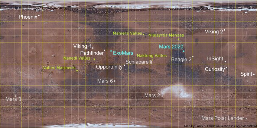
LuleåUniversity of Technology
Department of Computer Science, Electrical and Space Engineering

   Planetary Rover Wheel and Lower Leg
     Structural Design to Reduce Rock
              Entanglements

                                                               Supervisor:
                                                  Dr.-Ing. Florian Cordes
  Author:
                                                              Examiners:
  Natalie Lawton
                                               Prof. George Nikolapolous
                                        Prof. Dr. Dr. h.c. Frank Kirchner

                   A thesis submitted for the degree of

                         MSc Spacecraft Design

                           13th February 2020
Abstract
This thesis looks at the SherpaTT planetary rover. The rover is a hybrid walking and driving
rover that has been developed and built by DFKI and has already been deployed on several Mars
analogue field studies. The SherpaTT rover wheels were found to become entangled in rocks during
the last field deployment in Morocco. As human intervention would be impossible on Mars the
aim is to reduce the possibility of rock entanglements by performing a mechanical redesign of the
wheels. During this redesign care is taken to ensure the current traction, slip-resistance, weight
and strength are not adversely affected. In addition, the durability of the wheels is investigated in
terms of materials to review whether the current wheels are suitable for a mars deployment. An
investigation into the grousers design results in a changed design that aims to both reduce rock
entanglements and increase wheel performance by optimising the grouser height and number over
several different wheel and terrain cases. Wheels are produced for four scenarios, a rigid wheel on
hard ground, a rigid wheel on soft ground, a flexible wheel on hard ground and a flexible wheel on
soft ground. A conceptual investigation into the wheel fork design is carried out to examine the
effects of changing three properties of the wheel fork. The magnitude and location of the stress is
compared for each. Materials are investigated resulting in the recommendation of several potential
material choices which provide an increase in the overall strength and hardness. While SherpaTT
is still in development the 6000 class of aluminium is recommended due to the relative ease with
which it can be worked with. Once SherpaTT moves onto the final stages it is recommended that at
least the grousers are made from the 7000 class of aluminium, which have higher levels of strength
and hardness.
Acknowledgements
I would first like to express my gratitude to my supervisor, Dr.-Ing. Florian Cordes, for all the
help and advice he has provided to enable me to complete this thesis and to Professor George
Nikolakopoulos for assessing my work.
I would also like to acknowledge my colleagues at DFKI, Bremen, who willingly gave their time to
provide feedback and observations on my work, thus facilitating improvements to it.
In particular I am grateful to Prof. Dr. Dr. h.c. Frank Kirchner, Andrej Kolesnikov, B.SC.
and Jonathan Babel, B.SC. for their invaluable time as well as the comments and criticism they
provided me.
I would like to thank all my friends for their support, especially Georges Labrèche, with whom I
have spent many hours locked in various stimulating discussions about Martian exploration.
Finally, I am appreciative of consistent support and encouragement during this sustained endeavour
that my family and my boyfriend have provided.
Contents

1 Introduction                                                                                                                                                          8
  1.1 Motivation and Scope .       .   .   .   .   .   .   .   .   .   .   .   .   .   .   .   .   .   .   .   .   .   .   .   .   .   .   .   .   .   .   .   .   .    8
  1.2 Rover System Overview        .   .   .   .   .   .   .   .   .   .   .   .   .   .   .   .   .   .   .   .   .   .   .   .   .   .   .   .   .   .   .   .   .    9
  1.3 Project Aim . . . . . . .    .   .   .   .   .   .   .   .   .   .   .   .   .   .   .   .   .   .   .   .   .   .   .   .   .   .   .   .   .   .   .   .   .   10
  1.4 Thesis Structure . . . .     .   .   .   .   .   .   .   .   .   .   .   .   .   .   .   .   .   .   .   .   .   .   .   .   .   .   .   .   .   .   .   .   .   11

2 Background                                                                                                                                                           12
  2.1 Parts Introduction . . . . . . . . .                 .   .   .   .   .   .   .   .   .   .   .   .   .   .   .   .   .   .   .   .   .   .   .   .   .   .   .   12
  2.2 Utah and Morocco Campaigns . .                       .   .   .   .   .   .   .   .   .   .   .   .   .   .   .   .   .   .   .   .   .   .   .   .   .   .   .   14
  2.3 Past Work on the SherpaTT . . . .                    .   .   .   .   .   .   .   .   .   .   .   .   .   .   .   .   .   .   .   .   .   .   .   .   .   .   .   16
  2.4 Previous Mars Rovers . . . . . . .                   .   .   .   .   .   .   .   .   .   .   .   .   .   .   .   .   .   .   .   .   .   .   .   .   .   .   .   16
  2.5 Previous Lunar Rovers . . . . . . .                  .   .   .   .   .   .   .   .   .   .   .   .   .   .   .   .   .   .   .   .   .   .   .   .   .   .   .   19
  2.6 Current Work on Planetary Rovers                     .   .   .   .   .   .   .   .   .   .   .   .   .   .   .   .   .   .   .   .   .   .   .   .   .   .   .   21
  2.7 State of the Art Technologies . . .                  .   .   .   .   .   .   .   .   .   .   .   .   .   .   .   .   .   .   .   .   .   .   .   .   .   .   .   23
  2.8 Martian Environment . . . . . . .                    .   .   .   .   .   .   .   .   .   .   .   .   .   .   .   .   .   .   .   .   .   .   .   .   .   .   .   26
  2.9 Potential Mission Locations . . . .                  .   .   .   .   .   .   .   .   .   .   .   .   .   .   .   .   .   .   .   .   .   .   .   .   .   .   .   28
  2.10 Wheel Terramechanics . . . . . . .                  .   .   .   .   .   .   .   .   .   .   .   .   .   .   .   .   .   .   .   .   .   .   .   .   .   .   .   32
  2.11 Durability . . . . . . . . . . . . . .              .   .   .   .   .   .   .   .   .   .   .   .   .   .   .   .   .   .   .   .   .   .   .   .   .   .   .   34
  2.12 Summary . . . . . . . . . . . . . .                 .   .   .   .   .   .   .   .   .   .   .   .   .   .   .   .   .   .   .   .   .   .   .   .   .   .   .   35

3 Design                                                                                                                                                               37
  3.1 Mission . . . . . . . . .    . . . . . . .               .   .   .   .   .   .   .   .   .   .   .   .   .   .   .   .   .   .   .   .   .   .   .   .   .   .   37
  3.2 Grouser and Wheel Fork       Parameters                  .   .   .   .   .   .   .   .   .   .   .   .   .   .   .   .   .   .   .   .   .   .   .   .   .   .   39
  3.3 Grouser Equation . . . .     . . . . . . .               .   .   .   .   .   .   .   .   .   .   .   .   .   .   .   .   .   .   .   .   .   .   .   .   .   .   44
  3.4 Preliminary Designs . .      . . . . . . .               .   .   .   .   .   .   .   .   .   .   .   .   .   .   .   .   .   .   .   .   .   .   .   .   .   .   48
  3.5 Durability Investigation     . . . . . . .               .   .   .   .   .   .   .   .   .   .   .   .   .   .   .   .   .   .   .   .   .   .   .   .   .   .   50
  3.6 Summary . . . . . . . .      . . . . . . .               .   .   .   .   .   .   .   .   .   .   .   .   .   .   .   .   .   .   .   .   .   .   .   .   .   .   52

4 Simulation Results                                                                                                                                                   54
  4.1 Flat Grouser . . . . . .     .   .   .   .   .   .   .   .   .   .   .   .   .   .   .   .   .   .   .   .   .   .   .   .   .   .   .   .   .   .   .   .   .   54
  4.2 Chevron Grouser . . . .      .   .   .   .   .   .   .   .   .   .   .   .   .   .   .   .   .   .   .   .   .   .   .   .   .   .   .   .   .   .   .   .   .   56
  4.3 Sawtooth Grouser . . .       .   .   .   .   .   .   .   .   .   .   .   .   .   .   .   .   .   .   .   .   .   .   .   .   .   .   .   .   .   .   .   .   .   58
  4.4 Rigid Wheel Spokes . .       .   .   .   .   .   .   .   .   .   .   .   .   .   .   .   .   .   .   .   .   .   .   .   .   .   .   .   .   .   .   .   .   .   60
  4.5 Flexible Wheel Spokes .      .   .   .   .   .   .   .   .   .   .   .   .   .   .   .   .   .   .   .   .   .   .   .   .   .   .   .   .   .   .   .   .   .   61
  4.6 Flexible Wheel Rim . .       .   .   .   .   .   .   .   .   .   .   .   .   .   .   .   .   .   .   .   .   .   .   .   .   .   .   .   .   .   .   .   .   .   62
  4.7 Full Wheel Assembly . .      .   .   .   .   .   .   .   .   .   .   .   .   .   .   .   .   .   .   .   .   .   .   .   .   .   .   .   .   .   .   .   .   .   64
  4.8 Comparison Wheel Fork        .   .   .   .   .   .   .   .   .   .   .   .   .   .   .   .   .   .   .   .   .   .   .   .   .   .   .   .   .   .   .   .   .   65
  4.9 Double Wheel Fork . . .      .   .   .   .   .   .   .   .   .   .   .   .   .   .   .   .   .   .   .   .   .   .   .   .   .   .   .   .   .   .   .   .   .   68
  4.10 Taller Wheel Fork . . .     .   .   .   .   .   .   .   .   .   .   .   .   .   .   .   .   .   .   .   .   .   .   .   .   .   .   .   .   .   .   .   .   .   70
  4.11 Slanted Wheel Fork . .      .   .   .   .   .   .   .   .   .   .   .   .   .   .   .   .   .   .   .   .   .   .   .   .   .   .   .   .   .   .   .   .   .   72
  4.12 Summary . . . . . . . .     .   .   .   .   .   .   .   .   .   .   .   .   .   .   .   .   .   .   .   .   .   .   .   .   .   .   .   .   .   .   .   .   .   74

5 Final Results                                                                                                                                                        75
  5.1 Final CAD . . . . . . . . . . . . . . . . . . . . . . . . . . . . . . . . . . . . . . . .                                                                        75
  5.2 Durability Investigation Results . . . . . . . . . . . . . . . . . . . . . . . . . . . . .                                                                       79
  5.3 Summary . . . . . . . . . . . . . . . . . . . . . . . . . . . . . . . . . . . . . . . . .                                                                        80

                                                                   2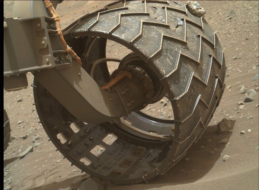
6 Discussion                                                                                       81
  6.1 Summary . . . . . . . . . . . . . . . . . . . . . . . . . . . . . . . . . . . . . . . . .    81
  6.2 Conclusion . . . . . . . . . . . . . . . . . . . . . . . . . . . . . . . . . . . . . . . .   83
  6.3 Improvements and Future Work . . . . . . . . . . . . . . . . . . . . . . . . . . . . .       84

Bibliography                                                                                       92

                                                  3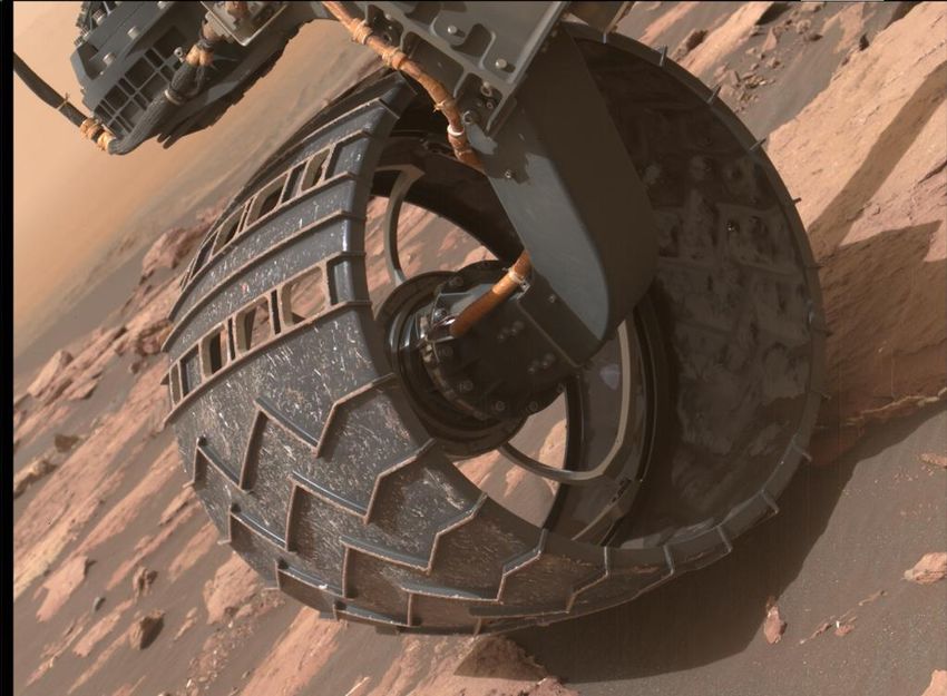
List of Figures
1.1 Sherpa Rover . . . . . . . . . . . . . . . . . . . . . . . . . . . . . . . . . . . . . . . 9
1.2 SherpaTT During the Morocco Field Tests . . . . . . . . . . . . . . . . . . . . . . . 10
2.1 Labelled Diagram of SherpaTT’s Wheel and Lower Leg . . . . . . . . . . . . . . . 12
2.2 Rock stuck on one of Curiosity’s six wheels . . . . . . . . . . . . . . . . . . . . . . 15
2.3 SherpaTT Wheel Fork Stuck on Rock During Morocco Field Tests . . . . . . . . . 16
2.4 Sojourner rocker and wheel assembly . . . . . . . . . . . . . . . . . . . . . . . . . . 17
2.5 Two of the MER wheels with the yellow Solimide infill . . . . . . . . . . . . . . . . 17
2.6 Entrance and exit tracks of Opportunity after freeing itself from a sand dune known
as Purgatory Ripple . . . . . . . . . . . . . . . . . . . . . . . . . . . . . . . . . . . 18
2.7 One of Curiosity’s six wheels . . . . . . . . . . . . . . . . . . . . . . . . . . . . . . 19
2.8 Wire mesh wheels from the Russian Lunokhod lunar rover . . . . . . . . . . . . . . 20
2.9 Wire mesh wheels from the American Apollo lunar rover . . . . . . . . . . . . . . . 20
2.10 Wire mesh wheels from the Chinese Yutu lunar rover . . . . . . . . . . . . . . . . . 21
2.11 Detailed view of Rosalind Franklin (Exomars) wheel . . . . . . . . . . . . . . . . . 22
2.12 Perseverance rover wheels . . . . . . . . . . . . . . . . . . . . . . . . . . . . . . . . 23
2.13 Origami wheel fully extended and fully folded . . . . . . . . . . . . . . . . . . . . . 23
2.14 NASA’s most recent wire mesh wheel . . . . . . . . . . . . . . . . . . . . . . . . . . 24
2.15 Spherical rover . . . . . . . . . . . . . . . . . . . . . . . . . . . . . . . . . . . . . . 24
2.16 Paddle wheels various configurations . . . . . . . . . . . . . . . . . . . . . . . . . . 25
2.17 Potential method of controlling a rover’s centre of gravity . . . . . . . . . . . . . . 25
2.18 Strain gauges interacting with wheel grousers . . . . . . . . . . . . . . . . . . . . . 26
2.19 Omnidirectional wheel potential configuration . . . . . . . . . . . . . . . . . . . . . 26
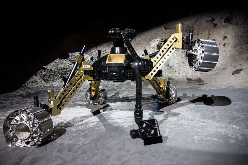
2.20 Map of Mars showing potential mission locations, previous succesful missions, previous
failed missions and planned missions . . . . . . . . . . . . . . . . . . . . . . . . . . 29
2.21 Nanedi Valles inner channel . . . . . . . . . . . . . . . . . . . . . . . . . . . . . . . 29
2.22 Eastern termination of Naktong Valles . . . . . . . . . . . . . . . . . . . . . . . . . 30
2.23 Mamers valley floor and one side of the valley wall . . . . . . . . . . . . . . . . . . 30
2.24 Valles Marineris topography and internal locations . . . . . . . . . . . . . . . . . . 31
2.25 Nilosyrtis Mensae layered deposits . . . . . . . . . . . . . . . . . . . . . . . . . . . 31
2.26 Forces acting upon a static rigid wheel on soft ground . . . . . . . . . . . . . . . . 33
2.27 Scarecrow version of the Curiosity rover . . . . . . . . . . . . . . . . . . . . . . . . 35
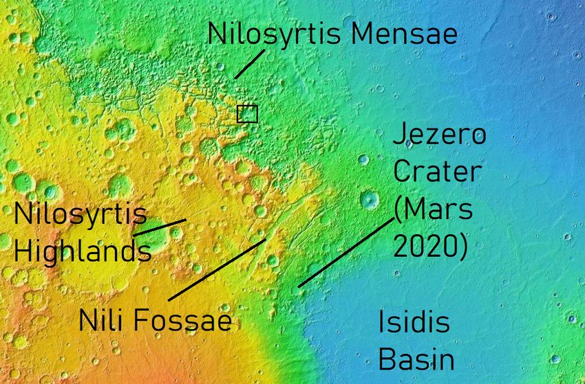
3.1 A topographical map and other notable locales around Nilosyrtis Mensae . . . . . 38
3.2 A topographical map and other notable locales around Nilosyrtis Mensae . . . . . 39
3.3 Figure showing how the angle, spacing and height of the grousers can be altered. . 40
3.4 Figure showing how the shape and pattern of the grousers can be altered. . . . . . 40
3.5 Figure showing how the angle (b), clearance, thickness (f) and electronics (d/e)
could be altered on the wheel fork where (a) shows the original configuration. . . . 43
3.6 Graph showing how the rolling resistance varies with sinkage. . . . . . . . . . . . . 45
3.7 Graph showing how the grouser height varies with the grouser number and regolith
type. . . . . . . . . . . . . . . . . . . . . . . . . . . . . . . . . . . . . . . . . . . . . 46
3.8 Grouser that uses a fold at each end to wrap around the edge of the wheel surface
where it is secured in place with a screw. . . . . . . . . . . . . . . . . . . . . . . . . 48
3.9 Grouser that uses a second piece of metal on the underside of the wheel surface that
pins it in place. . . . . . . . . . . . . . . . . . . . . . . . . . . . . . . . . . . . . . . 48
3.10 Chevron shaped grouser attached via one long tab running along its length. . . . . 48
4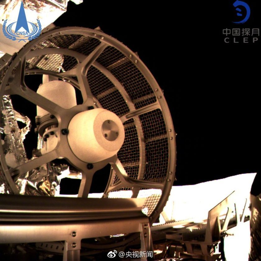
3.11 Grouser that has a zig-zag shape and is attached using metal tabs on either side of
     the grouser. . . . . . . . . . . . . . . . . . . . . . . . . . . . . . . . . . . . . . . . .     49
3.12 Grouser that has a wave pattern and small tabs to attach it to the wheel surface. .              49
3.13 The initial wheel designs using a chevron pattern a) and a straight pattern b). . .              50

4.1    Image showing the set-up of the flat grouser prior to simulation. . . . . . . . . . .          55
4.2    Figure showing the simulation result for the flat grouser under a load of 850 N. . .           55
4.3    Figure showing the set-up of the distributed load on the chevron grouser before
       simulation. . . . . . . . . . . . . . . . . . . . . . . . . . . . . . . . . . . . . . . . .    56
4.4    Figure showing the set-up of the concentrated load on the chevron grouser before
       simulation. . . . . . . . . . . . . . . . . . . . . . . . . . . . . . . . . . . . . . . . .    57
4.5    Figure showing the simulation result for the chevron grouser under a distributed
       load of 850 N . . . . . . . . . . . . . . . . . . . . . . . . . . . . . . . . . . . . . . .    57
4.6    Figure showing the simulation result for the toothed grouser under a load of 450 N.
       The view is from below to show the area where the maximum stress is occurring. .               58
4.7    Image showing the set-up of the sawtooth grouser prior to simulation where multiple
       points are used to apply the force. . . . . . . . . . . . . . . . . . . . . . . . . . . .      59
4.8    Figure showing the simulation result for the toothed grouser under a load of 450 N.
       The view is from below to show the area where the maximum stress is occurring. .               59
4.9    Image showing the set-up of the rigid wheel spokes prior to simulation. . . . . . . .          60
4.10   Figure showing the simulation result for the rigid wheel spokes under a load of 850 N.         61
4.11   Image showing the set-up of the flexible wheel spokes prior to simulation. . . . . .           62
4.12   Figure showing the simulation result for the flexible wheel spokes under a load of
       850 N. . . . . . . . . . . . . . . . . . . . . . . . . . . . . . . . . . . . . . . . . . . .   62
4.13   Image showing the set-up of the flexible wheels inner rim prior to simulation. . . .           63
4.14   Figure showing the simulation result for the inner wheel rim of the flexible wheel
       under a load of 850 N. . . . . . . . . . . . . . . . . . . . . . . . . . . . . . . . . . .     63
4.15   Image showing the set-up of the rigid wheel prior to simulations . . . . . . . . . . .         64
4.16   Figure showing the simulation result for full rigid wheel design. . . . . . . . . . . .        65
4.17   Figure showing the simulation result for full rigid wheel design zoomed into the area
       where the maximum stress of 6.692 ˆ 107 N {m2 is occurring. . . . . . . . . . . . . .          65
4.18   Image showing the set-up of the conceptual version of the comparison wheel fork
       prior to simulations. . . . . . . . . . . . . . . . . . . . . . . . . . . . . . . . . . . .    66
4.19   Figure showing the simulation result for the conceptual model of the comparison
       wheel fork with a maximum stress value of 3.219 ˆ 109 N {m2 . . . . . . . . . . . . .          67
4.20   Figure showing the simulation result for the conceptual model of the comparison
       wheel fork with the scale going up to a maximum stress value of 2.000 ˆ 108 N {m2
       to allow an easier comparison with the other models. . . . . . . . . . . . . . . . . .         67
4.21   Image showing the set-up of the conceptual version of a double wheel fork prior to
       simulations . . . . . . . . . . . . . . . . . . . . . . . . . . . . . . . . . . . . . . . .    68
4.22   Figure showing the simulation result for the conceptual model of a double wheel
       fork with the scale showing the maximum stress of 1.452 ˆ 109 N {m2 . . . . . . . .            69
4.23   Figure showing the simulation result for the conceptual model of a double wheel fork
       with the scale going up to a maximum stress value of 2.000 ˆ 108 N {m2 to allow an
       easier comparison with the other models. . . . . . . . . . . . . . . . . . . . . . . .         69
4.24   Image showing the set-up of the conceptual version of the taller wheel fork prior to
       simulations . . . . . . . . . . . . . . . . . . . . . . . . . . . . . . . . . . . . . . . .    70
4.25   Figure showing the simulation result for the conceptual model of the taller wheel
       fork with a maximum stress value of 3.994 ˆ 109 N {m2 . . . . . . . . . . . . . . . . .        71
4.26   Figure showing the simulation result for the conceptual model of the taller wheel
       fork with the scale going up to a maximum stress value of 2.000 ˆ 108 N {m2 to allow
       an easier comparison with the other models. . . . . . . . . . . . . . . . . . . . . . .        71
4.27   Image showing the set-up of the conceptual version of a slanted wheel fork prior to
       simulations. . . . . . . . . . . . . . . . . . . . . . . . . . . . . . . . . . . . . . . . .   72
4.28   Figure showing the simulation result for the conceptual model of the slanted wheel
       fork with a maximum stress value of 3.058 ˆ 109 N {m2 . . . . . . . . . . . . . . . . .        73

                                                 5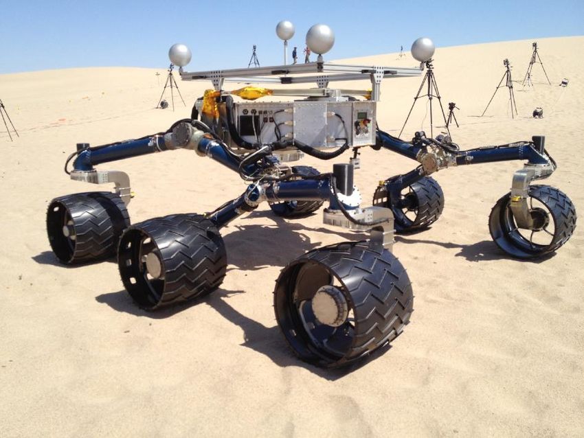
4.29 Figure showing the simulation result for the conceptual model of the slanted wheel
     fork with the scale going up to a maximum stress value of 2.000 ˆ 108 N {m2 to allow
     an easier comparison with the other models. . . . . . . . . . . . . . . . . . . . . . .   73

5.1   Figure showing the final CAD for a rigid wheel on coarse sand. . . . . . . . . . . .     76
5.2   Figure showing the final CAD design for the rigid wheel on soft sand. . . . . . . .      77
5.3   Figure showing final CAD for the flexible wheel on hard ground. . . . . . . . . . .      78
5.4   Figure showing the simulation result for the toothed grouser under a load of 450 N.
      The view is from below to show the area where the maximum stress is occurring. .         79

                                              6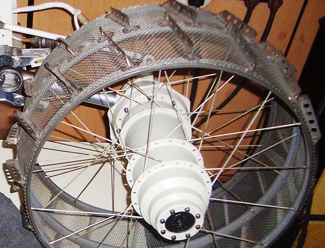
List of Tables

 2.1   Martian Regolith Types and Classification . . . . . . . . . . . . . . . . . . . . . . .   27

 3.1   ESA Martian soil properties . . . . . . . . . . . . . . . . . . . . . . . . . . . . . . . 44
 3.2   Grouser equation results showing what the predicted optimum height and number
       of grouser would be if the SherpaTT current grouser height or grouser number was
       kept the same. The predicted values are shown in italics. . . . . . . . . . . . . . . . 47
 3.3   Table showing suggested grouser parameters for four cases. . . . . . . . . . . . . . 47
 3.4   Mechanical Properties of Several Considered Materials . . . . . . . . . . . . . . . . 51
 3.5   Mechanical Properties of Metal Alloys which Remain Ductile at Cryogenic Temperatures 51

                                                7
Chapter 1
Introduction
This chapter introduces the motivations, scope and goals which provide the basis for this thesis.
Additionally a brief introduction to the Martian rover system that the project is been based upon
is included.
1.1 Motivation and Scope
Since humankind first started to explore space the goal has always been to develop a deeper
understanding of the universe surrounding us. In order to accomplish this there are five potential
methods. The first is studying from afar using a telescope, the second is using an orbiter to fly
close to or around a particular celestial body of interest, the third, fourth and fifth are placing
a lander, a rover or human explorers on the surface of a celestial body. Which method is most
appropriate depends upon the type of celestial body or event, the distance from Earth and the
type of science that is being targeted.
For this thesis Mars has been chosen as the celestial body of interest. Mars today is a barren planet
with little atmosphere, however, there is evidence of a much wetter past [1], [2], [3]. By learning
more about Martian history scientists hope to gain a deeper understanding of both Mars and of
the planetary processes which have caused such changes in the Martian climate. It is additionally
hoped that humans can colonise Mars [4], [5] and searching for clues to Mars’ wetter past should
be able to provide ways in which humans can sustain themselves on Mars. Whilst there is an
aim to send humans to Mars this does not seem likely in the near future due to the huge costs
involved, the new technology that must be developed and tested to ensure humans can be sent and
returned safely from Mars and the increased risk of cross contamination between Earth and Mars.
Given this, there has been substantial interest in Mars with many countries and space agencies
sending a collection of orbiters, landers and rovers to the planet [6]. Orbiters have returned much
important information about Mars, including finding suitable landing sites for the landers and
rovers. However orbiters cannot complete any direct science on the Martian surface. For this a
lander or rover is required. Although a lander can return great surface data it is restricted to the
area in which it landed. As landing areas must be safe enough to land in they are often relatively
flat spaces, however, some of the more interesting science takes place down in the Martian valleys
and craters and up on the Martian mountains and volcanoes. For this a rover is required and in
order for a rover to move around efficiently wheels are required.
The wheels on a planetary rover are a critical component and have a huge impact on the mission
if they are to fail for any reason. Unlike Terrestrial rovers it is not possible to carry out repairs on
planetary rovers and as such any damage they take is permanent. In the best case scenario a failure
would lead to reduced mobility and in the worst case would completely immobilise the rover. If a
rover is completely immobilised it is no different from a lander. Therefore it is important that the
wheels do not fail.
There are several processes in which wheels could fail including;
8• Degradation of the wheel leading to the wheel falling apart.
• Failure of the wheel motors.
• Failure in an electrical connection between the wheel and the main power or logic boards.
• Entanglements in rocks or other surface debris inhibiting movement.
• Excessive sinkage in soft surfaces.
• Inadequate grip or traction on slippery or steep surfaces.
This thesis focuses on the rock entanglement failure mode and more specifically on rock entanglements
with the wheels grousers and the wheel fork. To enable this the SherpaTT rover will be used as
the basis for this research.
1.2 Rover System Overview
The SherpaTT rover is a robot designed and built by DFKI [7]. It is a hybrid walking and driving
rover which is able to transport modular payloads in order to carry out science. Due to the
hybridisation of the walking and driving modes SherpaTT is able to access areas that may be
otherwise unreachable by more traditional rovers whilst still maintaining an efficient drive motion
across more benign terrain. SherpaTT is the successor of the Sherpa rover, both rovers are briefly
described in the following sections.
1.2.1 Sherpa
The original Sherpa rover, seen in Figure 1.1 was constructed as part of the RIMRES project which
aimed to develop technologies which would allow complex tasks to be carried out in difficult areas
through the use of modular and re-configurable robots [8]. Using an actuated suspension system
the Sherpa rover was able to drive both with wheels and by using a stepping motion when the
terrain became too difficult to traverse purely by driving [9]. The Sherpa rover is now retired as
it’s successor, the SherpaTT, is complete.
Figure 1.1: Image showing the original Sherpa rover
91.2.2 SherpaTT
SherpaTT, seen in Figure 1.2, is the successor of Sherpa and builds upon the strengths of Sherpa
whilst improving on the Sherpa’s weaknesses [10]. SherpaTT maintains the hybrid driving and
stepping capabilities of the Sherpa rover, retaining the ability to traverse over more complex
terrain. Changes were made in the legs where knee joints were added providing an increased range
of movement, whilst two rarely used joints that provided the 6th Degree of Freedom (DOF) were
removed [11]. SherpaTT therefore has an increased degree of flexibility in movement compared to
Sherpa. SherpaTT has now completed two field tests, one in Utah and the second in Morocco,
where the rover has been tested in environments similar to ones it may encounter on Mars.
Figure 1.2: SherpaTT During the Morocco Field Tests
The biggest goal of the SherpaTT rover is to complete planetary exploration missions, with key
targets being Mars and the Moon. By using its high flexibility with its movement SherpaTT is
able to traverse terrain that is impossible for a rover that purely drives. This freedom of movement
allows for the exploration of previously unreachable areas. It also makes the rover more robust
than previous rovers in terms of entrapment as SherpaTT can walk out of many entrapments that
would permanently immobilise a rover with only a drive mechanism.
SherpaTT also has the potential to be used in Terrestrial applications where it is too dangerous
to send humans and the terrain too complex for a wheeled rover. Examples of this include areas
containing nuclear waste or underwater environments. A waterproof version of SherpaTT already
exists in the form of SherpaUW [12].
1.3 Project Aim
Whilst the SherpaTT is able to walk its way out of many difficult situations it has been noticed
in field trials that two types of rock entanglement have been occurring. The first entanglement
occurs when a rock becomes wedged between the wheel tread and the grouser. The rock then
travels with the wheel as it turns until it reaches the top of the wheel where the clearance is too
low to allow it to pass. When this happens the rock jams the wheel preventing it from spinning
any further. This entanglement disables the motion of the wheel affected. The second is when the
rover is passing over or close to larger rocks which then become entangled in the rover wheel forks.
10When this occurs the rover beaches itself upon a rock leaving the wheel spinning freely in the air.
SherpaTT must then save itself by using the walking motion to step off the rock. Even though this
entanglement does not have as significant an effect as the grouser mode it is still an undesirable
occurrence for a rover that is intended for use in more challenging terrain. These entanglement
issues are covered in more depth in Section 2.2.
This project’s main aim is to make improvements to the current SherpaTT wheels and lower leg
structure to reduce the number of instances of rock entanglements. The primary ways in which
SherpaTT is currently becoming entangled is via the grousers and the wheel fork. Therefore, in
order to achieve reduced entanglement the grouser and wheel fork design are updated.
Whilst completing this primary aim the project also aims to ensure that other aspects of the
wheels performance are not adversely affected. Therefore careful consideration is made to the
grouser traction performance and the wheel fork stress profile.
Finally the durability of the wheel and lower leg structure is evaluated to ensure that it can
withstand the harsh Martian environment. Recommendations are made regarding materials and
structures.
The aims that are addressed by this thesis can therefore be summarised as follows;
• Reduce rock entanglements with the grousers
– Redesign grousers to remove primary methods of entanglement
– Investigate how the size, shape and number of grousers affects performance
– Rework wheel design to accommodate new grouser set-up
• Reduce rock entanglements with the wheel fork
– Investigate different wheel fork shapes
– Compare the magnitude and location of the stress in different wheel fork shapes
• Propose design to increase the durability of the wheel and lower leg structure
– Recommendations regarding wheel and grouser material
– Recommendations regarding wheel fork structure and material
1.4 Thesis Structure
This thesis is structured as follows:
Chapter 2: Background This chapter introduces the SherpaTT rover and the rock entanglement
problem in more detail. It then discusses past, current, future and state of the art work within
the field of rover wheels. The Martian environment is then explored and potential mission
sites identified. Wheel terramechanics is then introduced and the chapter ends with a note
on durability.
Chapter 3: Design This chapter takes the lessons learned from chapter 2 and begins to iterate
the design. The mission location is narrowed down and the key grouser and wheel fork
parameters are identified. Preliminary designs are found and a durability investigation takes
place.
Chapter 4: Simulation Results This chapter displays the how the simulations were set-up, the
results and the interpretations and conclusions for each of the designed parts.
Chapter 5: Final Results This chapter shows the final wheel designs and explains how they
were arrived at. Notes are made on the wheel fork structure that is best suited for the
wheels. The chapter ends with the results from the durability investigation.
Chapter 6: Discussion This chapter summarises the work undertaken in this thesis and presents
the final conclusions. It then talks about what future work could be completed leading on
from this project.
11Chapter 2
Background
This chapter first provides a more detailed introduction to the SherpaTT rover, explaining the
different parts of the rover before talking about past field test campaigns and elaborating further
on the rock entanglement issues. Next the chapter describes previous and planned Martian rovers,
focusing on the wheel subsystem. Finally the Martian environment and wheel terramechanics are
covered.
2.1 Parts Introduction
The parts of the wheels and lower leg structure on the SherpaTT are listed and described here to
provide an overview of the wheel and lower leg structure system. Figure 2.3 shows where each part
is within the wheel and lower leg system.
Figure 2.1: Labelled Diagram of SherpaTT’s Wheel and Lower Leg.
122.1.1 Wheel Surface
The wheel surface, also known as the outer wheel rim, is the main body of the wheel that has
contact with the ground. The design of the wheel surface determines the shape, size and width of
the wheel. A connection to the rest of the lower leg structure is made through the attachment of
the wheel surface to the springs and spokes.
It is important that the wheel surface is durable enough to withstand driving over hard and
uneven surfaces without cracking or deforming beyond the point of failure for the wheel. As it is
important to minimise the weight of the rover where possible, providing enough durability is often
a delicate balance with the thickness of the wheel surface. Whilst wear on the wheels is inevitable,
particularly if the rover goes beyond its expected lifespan, there should not be any catastrophic
damage due to inadequate durability during a wheel’s expected lifetime. Additionally for rovers
with flexible wheel surfaces, such as SherpaTT [10] and the Exomars Rosalind Franklin rover [13]
the wheel thickness plays an important role in determining how much the wheel is able to flex, with
a thicker surface providing a more rigid wheel and a thinner surface a more flexible wheel.
2.1.2 Grousers
The grousers are attached to the surface of the wheel and are generally spaced at regular intervals.
They provide increased traction for the wheels by utilising increased shear forces when they make
contact with the ground and by increasing the wheels effective radius when the gaps between the
grousers are filled with soil. Research also indicates that having a higher number of grousers and
having taller grousers acts to increase the total drawbar pull, though the benefits become less
significant after a certain point [14], [15], [16]. Sharp edges on the grousers also allow the wheel to
bite into rocks and other hard surfaces when travelling over them thus decreasing the amount of
slip [17].
On the current SherpaTT model the grousers have a saw-tooth edge and are placed in pairs with
a 45˝ angle normal to the wheel surface. SherpaTT has 10 grouser pairs.
2.1.3 Springs
The springs in SherpaTT’s wheels connect the wheel surface to the spokes. The springs allow
the wheel to flex more than it would using stiff spokes. The current SherpaTT wheel deforms by
approximately 7mm under a load of 166kg, SherpaTT’s nominal mass [7]. Given that Hooke’s law
states that Fs “ k ¨ x, where F is the force acting on the spring, k is the spring stiffness and x is the
displacement of the spring from its original position, the spring stiffness of the springs currently
used on SherpaTT is therefore 233 N{mm.
2.1.4 Spokes
The spokes connect the springs to the wheel motor, sensor and wheel fork. They also provide
extra rigidity to the wheel and act to limit the maximum deformation of the wheel possible under
extreme cases.
2.1.5 Wheel Fork
The wheel fork connects the wheel to the main leg of the rover. This important component must
be able to withstand many different stresses having the weight of the rover above it exerting force
downwards, upward forces from the wheel moving over uneven terrain below it, turning torques
acting on it from the wheel steering and shear forces as the wheel traverses slopes.
132.1.6 Sensors
The wheel torque sensor is currently located in the central part of the wheel and lower part of the
wheel fork, measuring both the wheel spin torque and the forces acting on the wheel. Looking at
the torque measurements allows it to be easily seen whether the rover is moving or stuck when the
motor is running, while the force readings provide information on the ground contact of the wheel
which allows for active ground adaption control.
As this sensor currently sticks out of the wheel, increasing the width of the lower leg structure,
there is the potential to move it into the the upper part of the wheel fork where it would measure
the wheel direction torque instead.
2.1.7 Wheel Drive Motor
The drive motor is located in the centre of the wheel and provides the turning force to spin the
wheel. The drive motor dictates the minimum size the central part of the wheel can be which
impacts on the rest of the wheel design when the wheel size is limited by constraints such as
launcher size.
2.2 Utah and Morocco Campaigns
SherpaTT has currently been on two field campaigns, the first in Utah and the second in Morocco.
Due to the rockier nature of the Morocco campaign rock entanglement was not seen until this
campaign.
The Utah campaign took place in 2016 making use of the similarities of the Utah desert and Mars
to validate the SherpaTT’s ability to function in such an environment. Three different natural
terrain test tracks were identified for the rover to follow to observe the rovers performance in
several different scenarios. A flat surface of 20 m was used for the first, for the second a partially
flat 12 m track was used with a 4 m long slope of approximately 8˝ ’s inclination during the central
part of the traverse and finally a 17 m sloped track with up to 28˝ ’s inclination. All runs were
completed at a constant velocity of 0.1 m{s with the exception of the last runs on the sloped track
which experienced 100 % slip after the duricrust was broken and had to be completed at 0.4 m{s
[7].
The Morocco campaign took place in 2018 also making use of the similarities between the Terrestrial
environment in the Moroccan desert and Mars. However the Moroccan field test environment had
some differences to the Utah environment. In Morocco the rocks were far more numerous that
in Utah. The increased prevalence of rocks brought to light some previously unseen issues. It
was noticed that the rover was having several negative interactions with the rocks where the rover
would become entangled via two main situations.
2.2.1 Rock Entanglement via Grousers
This first rock entanglement situation was the more common of the two. Rocks would get stuck in
between the grousers and the wheel surface. They would then travel with the wheel as it turned
and become stuck in in the gap between the wheel and the top of the wheel fork. The wheel would
then be unable to turn freely immobilising the wheel.
During the design phase of SherpaTT this rock entanglement possibility was considered, however
it was thought that any rocks which became trapped in this method would be able to simply fall
off naturally without causing any problems to SherpaTT. As this has since proven to not be the
case this thesis will investigate the causes to the rock entanglement and propose design changes to
prevent or reduce entanglements.
There are several factors about the wheels current design that could be contributing to this
situation. First, these rock entanglements could be due to the angle at which the grousers are
14mounted at. As they are mounted at 45˝ , as seen in Figure 2.1, to the wheels surface this makes
it easier for rocks to become wedged in this gap compared to grousers which are mounted at 90˝ .
Second, the clearance between the wheel and the top of the wheel fork is fairly small. Having a
small clearance means that more rocks that do become stuck cannot pass this point on the wheel
as they are too large to fit through the gap, reducing the chances that the rock will self remove.
Third, the entanglement could be linked with the spacing of the grousers. Currently SherpaTT has
ten double grousers spaced at regular intervals. However as the grousers are doubled this provides
another potential rock entanglement location. These factors are further investigated later in the
thesis.
It was noticed that Curiosity got a rock stuck between its grousers, as seen in Figure 2.2. However,
due to the huge amount of clearance between the wheel surface and any structures above the wheel
the rock was able to continue turning with the wheel until it fell off naturally [18].
Figure 2.2: Rock stuck on one of Curiosity’s six wheels [18]
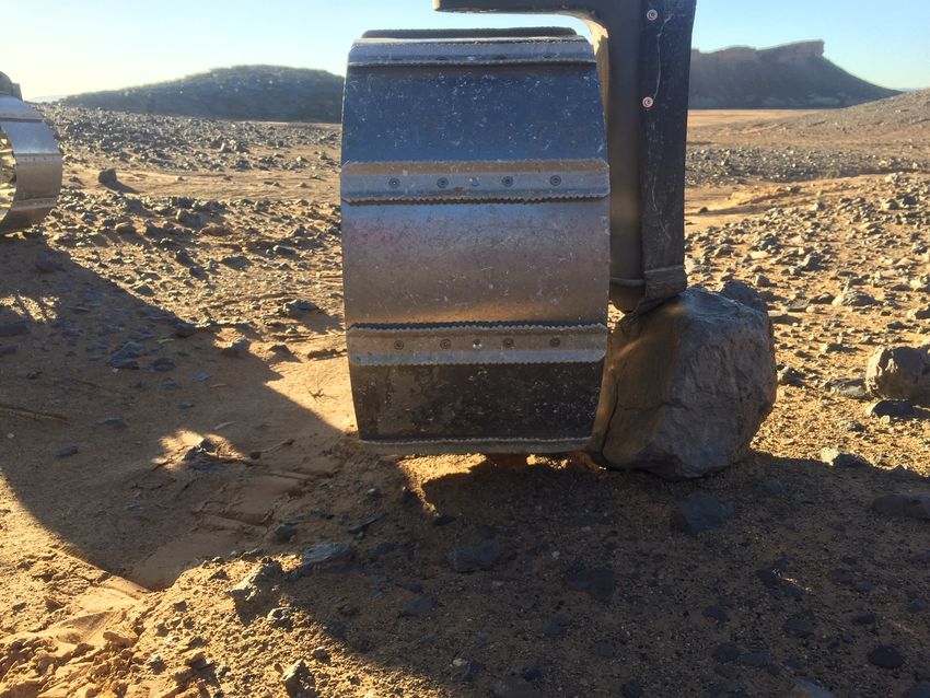
2.2.2 Rock Entanglement via Wheel Fork
Occasionally when driving during the Morocco field campaign the wheel would become marooned
on larger rocks. This would occur when the wheel fork would become stuck on top of a rock leaving
the wheel spinning freely in the air below. In these situations the only way for the rover to free
itself was to perform a stepping manoeuvre. Whilst it is possible for the rover to free itself from this
type of rock entanglement it is preferable that it is not a situation which occurs frequently.
This kind of entanglement has not been noted during any of the previous Martian rover missions.
However, this is possibly due to the way in which the rovers are designed. SherpaTT has the
ability to turn its wheels through nearly 360 degrees. None of the previous Martian rovers have
this capability. Therefore it was possible to ensure that the wheel fork always came in towards
the rover. As each rover has a certain amount of clearance between its body and the ground it is
important to try and ensure that the rover is not driving over anything that it could beach itself
upon, thus reducing the possibility of a wheel fork entanglement.
15Figure 2.3: SherpaTT Wheel Fork Stuck on Rock During Morocco Field Tests
2.3 Past Work on the SherpaTT
The original Sherpa rover featured flexible wheels created by the DLR-RM. Flexible wheels increase
the contact area with the ground, therefore increasing the traction of the wheel and allowing a
narrower wheel to obtain comparable performance to a wider wheel [19]. As the wheel flexes it
matches the ground it is travelling over decreasing the overall stress on the wheel and reducing
the amount of sinkage [20]. Whilst rigid wheels have superior performance on rigid ground the
performance of a rigid wheel significantly degrades on soft ground. The opposite is true for the
flexible wheel as the wheel does not sink as much on soft soils due to the increased ground contact
area [21].
The current SherpaTT also features flexible wheels, however the rigidity is much higher compared
to the previous iteration. The wheels currently used are similar to the proposed flexible wheels by
[20] and flex by approximately 7mm when under the nominal load of 166 kg, as described in more
detail in Section 2.1.3.
2.4 Previous Mars Rovers
As of present four rovers have successfully landed and operated on Mars. These are Sojourner,
Spirit, Opportunity and Curiosity. Each of these have had a number of successes and failures with
their locomotion system which can provide a valuable lesson.
2.4.1 Sojourner
Sojourner was part of NASA’s Pathfinder mission and was the first rover to land on Mars, touching
down on Mars in July 1997 in Ares Vallis. It acted as a proof of concept that it is possible to send
and operate a rover on Mars. Over several months Sojourner travelled approximately 100m, sending
images back via the Pathfinder lander, and opened the path for the future rovers [22].
Sojourner had six wheels of 130mm diameter and 160mm width. Each wheel used stainless steel
spikes to give it better grip on the Martian regolith and the rocker-bogey suspension allows the
16rover to surmount obstacles larger than the wheel diameter. As the first rover to drive on Mars
even less was known about how the wheels would perform on the Martian surface. To enable the
rover to drive through rocky terrain all the corner wheels could be individually steered allowing
the rover to turn through a small radius of 740mm [23], [24]. The wheels can be seen in Figure
2.4.
Figure 2.4: Figure showing Sojourner rocker and wheel assembly[25]
2.4.2 Spirit and Opportunity
Spirit and Opportunity were two identical rovers sent by NASA as part of the Mars Exploration
Rover (MER) programme as part of a mission to discover more about past water activity on Mars.
Spirit landed in the Gusev crater in January 2004 with Opportunity landing two weeks later on
the Meridiani Planum. Spirits mission lasted for over seven years or 2208 Martian Sols, with the
last communication from the rover received in March 2010 and the final communication sent to
the rover in May 2011. Opportunity’s mission lasted over 14 years or 5352 Martian Sols with the
last communication from the rover in June 2018 and the last communication sent to the rover in
February 2019. Spirit covered a total distance of 7.7km and Opportunity 45.16km, the largest
distance covered by any ground vehicle on another celestial body. Both rovers far exceeded their
initial 90 Sol mission [26], [27].
There were six wheels used on each of the MER rovers. Each wheel was 250mm in diameter
and was milled from a single piece of aluminium. This reduced the amount of excess weight and
stress points where parts would join together as screws or welding points were eliminated. As the
engineers were concerned about rock, dust and debris getting inside the wheels and interacting
negatively with the drive and steering mechanisms the yellow foam, Solimide, was added to fill in
the gaps [28]. Two of the wheels can be seen in Figure 2.5.
Figure 2.5: Figure showing two of the MER wheels with the yellow Solimide infill [28].
Both rovers had relatively few problems with their wheels during their missions. However both
rovers suffered from issues with both slip and sinkage. Opportunity become stuck for 5 weeks
17in a sandbank ripple that it was attempting to cross. When all six wheels were on the ripple
surface the rearmost wheels were bearing most of the load and began to sink into the sand.
The sinkage, compounded by very high slip, highly deformable terrain and increased compaction
resistance prevented Opportunity from moving forward. After careful manoeuvring Opportunity
was able to free itself and continue on until it was eventually taken out by the largest Martian
dust storm on record. The sand ripple and deep tracks of Opportunity can be seen in Figure
2.6 [29]. Spirit, however, became permanently entrapped in a soft sand area. The area it was
traversing over consisted of highly deformable sulphate rich soils which were covered by solid but
thin layer of basaltic sand. As the solid top layer hid the deformable ground underneath it was not
possible to detect dangerous areas ahead of time. Spirit became temporarily entrapped a few times
before it’s permanent embedding event in the Troy area. After the rover tilted and its front left
wheel became embedded in a sand trap all rescue attempts over the following nine months were
unfortunately unsuccessful. It then continued as a stationary science platform until its mission end
[26], [30].
Figure 2.6: Figure showing the entrance and exit tracks of Opportunity after freeing itself from a
sand dune known as Purgatory Ripple [29]
2.4.3 Curiosity
Curiosity was sent to Mars as part of NASA’s Mars Science Laboratory mission with the aim of
discovering if Mars ever had suitable conditions for life. Landing in the Gale crater in August 2012
Curiosity has currently covered over 21km [31].
At four times larger than its predecessors Curiosity’s wheels were updated from the MER rovers but
still maintain some similarity. The wheels are much larger, at 500 mm diameter and 400 mm width,
in order to carry the increased weight, and have a new grouser design using a chevron pattern.
The chevron pattern provides extra resistance against side slip, thereby improving the wheels
performance when traversing slopes. Additionally the chevron pattern granted a location where
sharp edges could be utilised to aid the rover when overcoming obstacles or climbing up rockier
surfaces. As with the MER rovers the wheel is machined from a singular piece of aluminium which
improves the mechanical properties of the wheel. However, Curiosity’s wheels do not have the
Solomide cover. This allows rock, dust and debris to flow in but also makes it easier to flow out
again [17] [32]. The wheel can be seen in Figure 2.7.
18Figure 2.7: One of Curiosity’s six wheels [18]
Curiosity’s wheels are made from hard anodised, aluminium alloy 7075-T7351 [33]. The 7000
aluminium alloy family have zinc as the major added element and often also contain magnesium,
copper and chromium in smaller quantities. These are most often used in aerospace and high
stress applications. The T73 temper provides an excellent stress corrosion cracking and exfoliation
resistance [34]. The grouser design on Curiosity is not based purely on the traction of the wheel. As
the wheels also functioned as the landing gear for the rover the grousers also had to bring structural
elements into the wheel. As such the design was, as it normally is, a compromise between different
areas [17].
A large factor in the Curiosity wheel design was around the weight of the wheels due to launcher
constraints. Consequently the wheels surfaces are only 0.75mm thick, the thinnest it was possible
to machine [17]. This had great weight savings, however it has caused issues with the mission.
During examinations of routine wheel photos that Curiosity sends back, it was noticed that the
wheels were degenerating at rates faster than expected [35] [32], [36]. The first breaks in the wheel
surface were noticed in October 2013, as the rover drove over an area with many sharp rocks
which were embedded in the bedrock [37] and the first breaks in the wheel grousers seen in March
2017 [38]. It has also been noted that tears are forming at the higher stress points at the pointed
tips of the grousers [32]. Whilst it was always expected that the wheels would degenerate over
time due to wear as the rate was alarming work began to investigate why wear was happening so
fast. The cause was found to be a combination of driving over particularly hard and sharp terrain
and from all the wheels driving at the same pace causing wheels to be dragged over obstacles.
After developing a new algorithm and completing successful testing on a model on Earth that has
the equivalent properties of Curiosity on Mars a traction control software has been employed to
increase the wheel life span. By controlling the speed of each individual wheel the chances of any
wheel being partially dragged over an obstacle is reduced. As each wheel can spin faster when
overcoming an obstacle it can keep up with the other unobstructed wheels which have a shorter
distance to travel. In addition driving plans now actively avoid these sharp embedded rock areas
[35], [36].
Curiosity also had a close encounter with a sand trap during Sol’s 709-711 when making an
attempted entry into Hidden Valley. During the descent down the ramp the wheel spin was
increasing sharply as the sand proved to be far more slippery than expected. However the rover
was able to retreat and on Sol 731 it was decided to reroute around the valley [39].
2.5 Previous Lunar Rovers
In addition to the rovers which have been sent to Mars there are also several which have been sent
to the moon. The wheel design for these rovers is quite distinct to those which have been sent to
Mars as the environmental conditions are very different. The moon is covered mostly in a very
19fine, loosely packed top soil that has a low cohesion. These soil conditions coupled with a gravity
of only 1.62 m{s, compared to the Martian gravity of 3.71 m{s and Earths 9.81 m{s, leads to the
choice of wheels which have a wire mesh structure in order to be as light weight as possible and
to provide an easy exit for lunar soil which ends up inside the wheel. Providing an easy exit for
the lunar soil makes it easier for the wheel to avoid extreme sinkage. Using a wire mesh structure
for the wheels has been possible on the moon as the reduced gravity reduces the stresses that the
wheels will experience. It is desirable to make the wheels as lightweight as possible as it reduces
the payload mass which leads to either a cheaper launch or the allowance to have a larger mass in
other areas of the design. Three agencies have successfully operated rovers on the Moon. The first
was Russia with the Lunokhod rover using a wire mesh supported by thin spokes and a solid rim
and angled grousers to aid traction, as seen in Figure 2.8. Second was NASA with the lunar roving
vehicle as part of the Apollo missions. The wheel can be seen in Figure 2.9 where inner metal
bands are used to support the wire mesh frame of the wheel. Finally the Chinese Yutu rover as
part of the Chang’e mission used a design similar to the Lunokhod wheel but with larger spokes,
as seen in Figure 2.10.
Figure 2.8: Figure showing one of the wire mesh wheels used on the Russian Lunokhod rover [40].
Figure 2.9: Figure showing one of the wire mesh wheels used on the American Apollo lunar rover
[41].
20Figure 2.10: Figure showing one of the wire mesh wheels used on the Chinese Yutu rover [42].
2.6 Current Work on Planetary Rovers
As of present there are currently two rovers aiming for a 2020 launch date and one for a 2022.
ESA’s Rosalind Franklin Rover as part of the Exomars mission, NASA’s Perseverance rover as part
of the Mars 2020 mission and China’s HX-1 rover. As there is very little available information on
the HX-1 rover it will not be presented further.
2.6.1 Rosalind Franklin (Exomars)
ESA’s Rosalind Franklin rover is part of the Exomars mission which is a joint venture with Russia
and part of a bigger joint mission with NASA’s Perseverance rover. Rosalind is due to land on Mars
in 2023 [43]. The mission aim is to search for and collect samples that could provide information
about the biological past of Mars. With a targeted mission lifetime of around 7 months, or 218
Martian Sols the rover will be required to drive several kilometres [13].
Rosalind is around the same size as the MER Rovers and will use a similar airbag descent. The
wheel design was heavily influenced by lander imposed size constraints as in order to fit inside the
lander the wheels could not be too wide. The wheels will be 285mm diameter and 120mm wide and
can be seen in Figure 2.11. To overcome the loss of traction from having narrower wheels Rosalind
employs flexible wheels in order to increase the wheel-soil contact area which reduces the ground
pressure [13]. Using flexible wheels also provides other positive effects such as reduced sinkage on
soft ground, as discussed in Section 2.3.
21Figure 2.11: Figure showing a detailed view of the Rosalind rovers wheel [13]
Alongside the Perseverance rover Rosalind aims to collect samples of the Martian regolith with the
aim being for a later mission to return them to Earth [43].
2.6.2 Perseverance (Mars 2020)
NASA’s part of the joint venture with ESA and Russia is the Perseverance rover, due to land
on Mars in February 2021 in the Jezero crater. With an expected mission time of at least one
Mars year, or 687 Earth days, the Perseverance rover will study and collect soil and rock samples
to search for signs of micro-bacterial life. The collected samples will then be collected by a later
mission for a return to Earth [44], [45].
The Perseverance rover is heavily based upon the design of Curiosity. However with the information
on the state of Curiosity’s wheels there has been some redesign with the wheels. The wheels will
have a thicker skin to prevent penetration happening so readily whilst also changing the grouser
pattern to a wave to eliminate the pointed edges causing localised areas of higher stress. The
number of grousers has been increased from 24 to 48, with tests showing an improved performance
on sharp rocks without degrading the wheel’s performance on sand [46]. The wheel will also be
narrower but with a larger diameter compared to Curiosity being 25 mm larger with a 525 mm
diameter[47], [48]. The rest of the wheel remains unchanged. The wheel for Perseverance can be
seen in Figure 2.12.
22Figure 2.12: Figure showing the wheels on the Perseverance rover [49].
2.7 State of the Art Technologies
In this section various state of the art technologies are examined to provide an overview of where
rover wheels may be headed in the future. Although some of these concepts are already in use
on Earth, or have been used on the Moon, none have been used on any past, present or planned
Martian rovers.
2.7.1 Oragami Wheels
An origami wheel is actively deformable, being able to change its diameter when commanded to
do so. With the wheel fully extended it has the ability to overcome larger obstacles and cross over
larger gaps, when the wheel is folded it is able to fit through smaller gaps. Having the ability to
adapt to its surroundings results in a wheel which is able to cover a variety of rugged terrains that
may be unreachable for a rover with conventional wheels. The difference between an extended and
folded wheel can be seen in Figure 2.13 [50].
Figure 2.13: Figure showing an origami wheel fully extended and fully folded [50]
2.7.2 Wire Mesh Wheels
Wire mesh wheels have been used previously on lunar missions, notably the Lunar Roving Vehicle
from the Apollo missions [41], as discussed in Section 2.5. However, new advances in this area
have produced wire mesh wheels that have the strength and flexibility to withstand Martian and
even Terrestrial usage, utilising the material properties of a titanium alloy and the mechanical
23properties of the mesh structure. NASA has expressed hopes of using this type of wheel, seen in
Figure 2.14, on some of its future rover missions [40].
Figure 2.14: Figure showing the most recent mesh wheel proposed by NASA [40].
2.7.3 Sphere Rover
The sphere rover wheels work by placing the entirety of the rover inside the wheels, creating a
spherical rover, as seen in Figure 2.15. Each side of the sphere is able to spin independently,
therefore being able to propel the rover forward, backwards and to spin the rover. A more recent
design adds a simple hopping mechanism to the base of the sphere allowing the rover to jump out
of places where it may have become stuck. The simplicity of the design makes this type of rover
is very suited to difficult and rugged terrain. One of the main drawbacks with this rover is its
physical limitations on science. The size of the sphere is limited and the shape of the space inside
does not lend itself well to conventional instruments. The instruments on board would also need
to be robust to ensure that regular hopping or potentially large impact forces from drops do not
damage or interrupt data collection [51].
Figure 2.15: Figure showing a spherical rover [51].
2.7.4 Adjustable Paddle Wheels
Adjustable paddle wheels attempt to combine a walking and rolling motion on the wheels. The
paddle lengths can be changed so that the rover is either entirely resting on the paddles, providing
the walking motion, or so that the paddles are essentially fully retracted and the rover rolls as if on
regular wheels, as seen in Figure 2.16. The advantage of this method is that on hard level ground
the most efficient form of locomotion is a pure rolling motion, however when in soft or sloping
ground longer grousers are preferable. This effective controllable grouser length allows for the
24wheels to adapt to the situation that they are in and gives the wheels a higher overall performance
[52].
Figure 2.16: Figure showing the various configurations of the paddle wheel [52].
2.7.5 Centre of gravity (CoG) Movement
Using CoG movement takes inspiration from nature where animals will shift their CoG forward
when climbing hills, particularly seen when animals such as camels climb sand dunes. This CoG
shift provides more efficient traction and reduced slip when applied to rovers. The CoG can be
moved in several ways such as using a movable weight to position the CoG in the most favourable
position, leaning a rover with walking capabilities forward as it climbs or by re-positioning any
movable instrumentation [53], [54]. One such method can be seen in Figure 2.17 where a movable
weight is used.
Figure 2.17: Figure showing a potential method of controlling the CoG of a rover [53].
2.7.6 Real Time Sinkage Detection
This concept aims to be able to detect when a wheel is beginning to sink in order to prevent
full entrapment from sinkage. The proposed method uses strain gauges connected to the grousers
to make real time measurements, as seen in Figure 2.18. If the rover detects that the wheel is
sinking it can then adjust itself to prevent further sinkage. By intervening before a wheel has sunk,
scenarios such as the one experience by the Spirit rover, where the wheels became too embedded
in the regolith, can be avoided [55].
25Figure 2.18: Figure showing how the strain gauges interact with the grousers on the wheel. [55]
2.7.7 Omnidirectional Wheels
Omnidirectional wheels, as seen in Figure 2.19, are already being used in the automation industry
where their ability to move in any direction is a valuable asset. Whilst they have been investigated
for potential use in a rover their inability to carry a high load means they are currently not suitable
for this kind of task [56].
Figure 2.19: Figure showing one possible configuration of an omnidirectional wheel [56].
2.8 Martian Environment
When designing a mission it is important to take into consideration the environment that the
parts will be exposed to. The Martian environment is very harsh with a thin atmosphere, extreme
temperature drops and a terrain that is still not fully understood. Parts used on a rover must
therefore be carefully selected and tested to ensure that they will survive these conditions.
2.8.1 Terrain
The Martian terrain is dominated by dust, sand and rocks in what is broadly known as the Martian
regolith. However, within this broad description are a range of different terrain types. Some areas
are covered in deep sand with rippling sand dunes, others are exposed bed rock, others are rock
debris fields, some are a mixture of all these types. Each type of terrain comes with its own unique
set of challenges. The deformable Martian regolith can be roughly broken down into four different
categories that would likely be traversed by a rover, as shown in Table 2.1 [13]. Each category
has been reproduced on Earth as an Engineering Soil Simulant (ES) to be as close as possible
to conditions on Mars. Rocky terrain such as exposed bedrock is not included in this scale as it
will not deform under the weight of a rover. As no regolith samples have yet been returned from
Mars these reproductions rely on limited data gathered by previous rovers, landers and orbiters
[57].
26Table 2.1: Martian Regolith Types and Classification
Regolith Classification Description Occurrence
Type
Fine Dust ES-1 Compressible, very fine grains, Outside of windy areas
porous and in wind shadows.
Fine Sand ES-2 Low cohesion and shear strength Troughs of sand dunes
Coarse ES-3 Moderate cohesion and shear Frequently occurs at the
Sand strength base of bedrock cliffs
Gravel ES-4 Don’t need to worry about Most common terrain
cohesion or shear strength outside of sand dune
anymore. Has a tendency to areas
clump together.
The key difference between the ES types lies within the mechanical properties of the soils. These
being the properties which define the shear strength, τ ; cohesion, C, and angle of internal friction,
φ, and those used in terramechanics; coefficient of cohesion, kC , coefficient of friction, kφ , and the
sinkage exponent, n. If these properties are known it is possible to determine whether the soil
will be able to support any given wheel or rover. As the mechanical properties of the soil change
depending on the humidity and packing density of the soil, amongst other properties, there are
many variations in the potential behaviour within each of the ES types as well [57]. However, until
material can be collected and successfully returned to Earth for testing it still cannot be truly
known how the wheels will behave when traversing the Martian regolith.
Of these four categories it is the lower classifications with the finer sand which are the trickiest
for a rover to traverse. This is particularly true if the soil is only loosely compacted, meaning the
density is low. High slip rates and sinkage are the two most dangerous aspects of driving through
sandy areas as both have the potential to immobilise a rover. These issues often come together as
when a rover is experiencing high slip rates there is a tendency for it to dig itself deeper into the
regolith thus suffering from sinkage too. Each of the Martian rovers, which have driven more than
a few 100m, have faced at least one moment during their mission where the slip rate was seen to
become exceptionally high as the sand is much slipperier than has been predicted [29], [30], [26],
[39]. Excessive sinkage in one dune proved to be the end of the mobile mission for the Spirit rover
[30], [26].
Exposed bed rock eliminates the risk of sinkage entirely however it brings a new risk. Due to the
hardness of the bedrock there is no give in the ground as the rover drives over it increasing the
forces acting upon the wheel. Where the exposed bedrock is jagged and pointy this problem is
exaggerated further as this creates high localised stress on the wheel which has the potential to
puncture the wheel surface [35], [37]. Increasing the stresses on the wheel accelerates the rate of
wheel degradation, reducing the wheel’s lifetime. Boulder fields can also be particularly tricky for
a rover to navigate, as well as posing a large risk to a landing craft. Where there are large rocks
that the rover cannot drive over the rover must go around. This increases the time it takes to drive
to a destination, reducing the number of potential science sites that the rover will be able to reach
[58].
Within these types of terrain regoliths also lie further terrain features. Mars is covered in many
craters of various sizes and ages creating shallow and deep basins with varying amounts of sediments
layered inside. Valleys cut across the landscape, thought to be formed by ancient water and glacial
processes, ranging from shallow valleys that are noticeable from escarpments to the enormous
depths of Valles Marineris at up to 7km deep [59]. Mesa’s and chaotic landscapes are found in
areas thought to have been formed by glacial processes. Finally Mars has many mountains that
are several kilometres high, thought to be formed via either volcanic processes or through sediment
deposits and erosion. This includes Olympus Mons, the largest known mountain in the solar system
at nearly 22 km high [60]. When considering a mission to Mars these features are often of high
scientific interest due to the high likelihood of accessible sedimentary layers and link with a wetter
and potentially more alive past. However these features create challenging terrain and present
steep, often scree covered, slopes.
27You can also read