Preliminary Proposal for an Alternative Wall Lining Panel Based on Molded Recycled Cellulose and Designed for Home Wiring Refurbishment of ...
←
→
Page content transcription
If your browser does not render page correctly, please read the page content below

sustainability

Article
Preliminary Proposal for an Alternative Wall Lining Panel
Based on Molded Recycled Cellulose and Designed for Home
Wiring Refurbishment of Building Interior Partitions
Raül Serra-Fabregà and Joan-Lluís Zamora-Mestre *

                                          ETS Arquitectura del Vallès, Universitat Politècnica de Catalunya (UPC), 08173 Sant Cugat del Vallès, Spain;
                                          raul.serra@upc.edu
                                          * Correspondence: joan.lluis.zamora@upc.edu; Tel.: +34-680-632-387

                                          Abstract: Old dwellings usually have shortfalls in insulation, acoustic and thermal, and in security
                                          of electrical services in the interior partition walls. A common building solution is to add a wall
                                          lining with a laminate base gypsum board that improves both acoustic and thermal insulation and
                                          facilitates a new invisible cable layout without demolition. Conventional solutions have had limited
                                          success because of time consumption, environmental impact and cost. This research aimed to create
                                          an integrated building system to carry out these interior building refurbishment works quickly,
                                          cleanly and with low inconvenience and environmental impact. The research specifically focused
                                          on incorporating new molded materials that have a low environmental impact and improving the

                                   handling and future modification of the wall lining system. In response to the above goals, the
                                          product development methodology was applied to the design of an internal panel to be inserted
Citation: Serra-Fabregà, R.;
                                          between the existing partition wall and the closure wallboard, which is usually laminated base
Zamora-Mestre, J.-L. Preliminary
                                          gypsum board (LGB). The proposed internalpanel is molded with recycled cellulose pulp (Biprocel)
Proposal for an Alternative Wall
Lining Panel Based on Molded
                                          and has adequate relief designed to improve cable layout tasks and better join the laminate base
Recycled Cellulose and Designed for       gypsum board to the existing wall face. The development resulted from collaboration between the
Home Wiring Refurbishment of              public administration, university researchers and undergraduate students in the co-design process.
Building Interior Partitions.             This research contributes to improving the applications of recycled cellulose fibers in molded panels
Sustainability 2021, 13, 4643. https://   for the building industry, particularly in refurbishment activities.
doi.org/10.3390/su13094643
                                          Keywords: molded panels; cellulose pulp; wiring layout system; wall lining; interior partitions;
Academic Editor:                          dwelling refurbishment
Jurgita Antuchevičienė

Received: 9 February 2021
Accepted: 1 April 2021
                                          1. Introduction
Published: 22 April 2021
                                                In Western countries, the housing sector is facing the widespread problem of refurbish-
Publisher’s Note: MDPI stays neutral
                                          ing urban-dwelling stock to update electrical services and improve insulation performance
with regard to jurisdictional claims in
                                          in line with the needs and aspirations of the population: increased comfort, reduced
published maps and institutional affil-   energy consumption and the introduction of home digitalization [1,2]. This improve-
iations.                                  ment in the built environment should occur in three stages: city, buildings and private
                                          dwellings, with a clear diversity in the available resources and governance systems [3,4] in
                                          different countries.
                                                Turnover in property owners and users occurs daily because of continuous social
Copyright: © 2021 by the authors.
                                          and individual changes. Each change in owner or user of a dwelling is accompanied by
Licensee MDPI, Basel, Switzerland.
                                          additional private investment to adapt the interior space to the new occupants. Interior
This article is an open access article
                                          partition walls are one of the building elements that are usually altered throughout its
distributed under the terms and           life cycle.
conditions of the Creative Commons              Building techniques for removing and replacing interior partition walls that are in
Attribution (CC BY) license (https://     use in the construction market are not very efficient in terms of time and waste at the
creativecommons.org/licenses/by/          building site, leading to high economic and environmental costs. This is probably because
4.0/).                                    these building techniques were developed in a historical period in which salaries were

Sustainability 2021, 13, 4643. https://doi.org/10.3390/su13094643                                       https://www.mdpi.com/journal/sustainability
Sustainability 2021, 13, 4643                                                                                              2 of 18

                                low, work processes were traditional, and site work could be disturbing and unhealthy for
                                the neighborhood because of noise, dust and waste. It is a challenge to update building
                                techniques for interior partition walls focusing on current social and climate changes.
                                Any reengineering of this interior building element must be aligned with the current
                                vectors of evolution:
                                (1)    Periodic changes in the user of the housing stock (rent and purchase);
                                (2)    Home-scale renewal, aligned with buildings and city refurbishment policies:
                                (3)    The growing need for more wired services (energy, security, sensors, lighting, com-
                                       munication, etc.) at home, which does not seem to be slowing;
                                (4)    New “green” refurbishment technologies to make the circular economy a reality [5].

                                2. Literature
                                     First, a review of the existing literature is presented, which allows us to group the
                                research into three sections: scientific-technical, industrial and commercial.

                                2.1. Current Situation of Electrical and Wire Services in Housing
                                      The safety of the oldest electrical installations in homes is a concern in European
                                Union countries, given the current renovation rate of homes and, more specifically, of their
                                electrical installations. In addition, using domestic electricity continues to grow and evolve.
                                Its intensity and complexity are increasing in terms of the quality and safety of electricity
                                used in homes alongside other aspects, such as home automation, telecommunications,
                                self-generation of power, etc. [6].
                                      The results of a study carried out in Spain [7] show in detail some qualitative and
                                quantitative aspects of this situation:
                                (1)    23.87% of living room switches have been modified from the original layout;
                                (2)    25.4% of bedroom switches have been modified from the original layout;
                                (3)    23.6% of kitchen switches have been modified from the original layout;
                                (4)    35.13% of living room sockets have been modified from the original layout;
                                (5)    40.93% of socket outlets are hidden by furniture;
                                (6)    35.20% of plug positions have been modified from the original layout;
                                (7)    38.07% of bedroom sockets are hidden by furniture;
                                (8)    29.6% of kitchen plugs have been modified from the original layout;
                                (9)    77.67% of plugs in living rooms connect adaptors, spools or extension cables;
                                (10)   64.20% of plugs in bedrooms have spools or extensions connected.
                                       In the case of telephony, data and TV networks, the following results were found:
                                (1)    31.7% of telephone connections are modified from the original layout;
                                (2)    16.7% of telephony connections in living rooms have been modified from the original layout;
                                (3)    38.5% of telephone connections in bedrooms have been modified from the original layout;
                                (4)    12.7% of telephone connections in bedrooms have been hidden by furniture;
                                (5)    33.3% of data and TV connections in living rooms have been modified from the
                                       original layout;
                                (6)    18.1% of data and TV connections in living rooms have been hidden by furniture;
                                (7)    40.7% of data connections and TV in bedrooms have been modified from the original layout;
                                (8)    13.8% of data and TV connections in bedrooms are hidden by furniture.
                                      This scientific-technical study reveals the need to develop specific technologies to
                                facilitate changes and/or the relocation of surface elements of the wired services that are
                                supported on interior wall partitions, not only for comfort but also for security (Figure 1).
Sustainability 2021, 13, 4643 3 of 18
Sustainability 2021, 13, x FOR PEER REVIEW 3 of 19
Figure 1.
Figure 1. Example
Exampleof
ofthe
thecurrent
currentsituation
situation
of of electrical
electrical andand wire
wire services
services in dwellings
in dwellings (source:
(source: au-
authors).
thors).
2.2. Commercial State of the Art
2.2. Commercial
The summaryState of thein
shown Art
Table 1 indicates that only a few technical systems are available
The
on the summary
building shown
market in layout
for the Table 1ofindicates that only aand
wired installations, fewnotechnical systems are
recent contributions
available
were on the
found. building
This market
situation for the
contrasts layout
with the of wiredscope
broad installations, andregulations
of current no recent con-
[8],
which allow a greater number of solutions than those that are currently implemented.
tributions were found. This situation contrasts with the broad scope of current regula-
However, the characteristics
tions [8], which allow a greaterof wiring
number areofcontinuously
solutions than evolving andare
those that diversifying, as
currently im-
shown in Table
plemented. 2.
However, the characteristics of wiring are continuously evolving and diver-
sifying, as shown in Table 2.
Table 1. Summary of wiring layout technologies in residential buildings (source: authors).
Table 1. Summary of wiring layout technologies in residential buildings (source: authors).
Strategies Weaknesses Strenuous Threats Opportunities
Strategies Weaknesses Produces Strenuous
noise, Threats Opportunities
dustProduces
and waste,noise,
Affects the basic
affects workers’
dust and waste,
performance of No need to
Affects the basic safety, and
Wall chasing the wall affects workers’Very cheap forecast
No need to
performance
(isolation, of the requires a future needs
Wall chasing safety, and re- Very cheap forecast future
wall (isolation, great deal
stability)
quires
of time a and
to do great deal needs
stability) undo activities
of time to do and
undo activities Available
Alters the visible everywhere
Availableand
Surface technical
No flatness architectural Easy handling with various
channels Alters the visible everywhere
Surface technical appearance kinds of
No flatness architectural ap- Easy handling and with var-
accessories
channels
pearance ious
Improves kinds
otherof
accessories
aspects of wall
Loss of habitable
Wall lining More expensive Not visible performance:
Improves oth-
volume
acoustic, fire,
er aspects of
thermal, etc.
Loss of habitable wall perfor-
Wall lining More expensive Not visible
volume mance: acous-
tic, fire, ther-
mal, etc.
Sustainability 2021, 13, 4643                                                                                                      4 of 18

                        Table 2. Summary of the standardized technical characteristics of the cabling that is considered.

                                   Cables                                                           Comments
          RZ1-K 0.6/1 kV, nominal sections of 1.5 and 2.5   mm2           Reference standards:
       Effective voltage (U) of 1 kV for use in fixed installations       •    Dimensions and material, UNE 21123-4;
                                                                          •    Identification of drivers, UNE 21089-1 (HD 308);
          Rated voltage 0.6/kV test voltage 3.5 kV C.A (5 min)            •    Fire behavior test, UNE 21123-4
        Cross-linked polyethylene (XLPE) insulation, type DIX3
                                                                                       According to Annex 1, UNE 21123-4
         according to HD 603-1. Cover made of polyolefin PO
                                                                           The nominal section of 1.5 mm2 is suitable for the supply of
                                                                                             10 A consumer lighting;
                                                                           The nominal section of 2.5 mm2 is suitable for feeding bases
                      Minimum radius of curvature
                                                                                              between 16 and 20 A;
             4Ø if Ø < 25 mm and 5Ø if 5 mm ≤ Ø ≤ 50 mm
                                                                           The outer Ø of these nominal sections is 5.7 mm and 6.2 mm,
                                                                            which means that the most restrictive radius of curvature
                                                                                                   is 24.8 mm.
            Electrolytically twisted flexible copper conductor
                                                                                  It is substantially cheaper than using a “hose”.
                class 5 according to UNE 21022/IEC 228
      Telephone conductors: cables of 1 pair EV 0.51 mm with an           It is comparable to most drivers used in pre-existing telephone
           outer diameter of 3.7 mm are taken as a reference.                             installations in the study area.
    Data conductors of 6.1 mm outer diameter FTP Class D, Cat5e           It is comparable to most of the conductors used in pre-existing
                   cables are taken as reference.                                    telephone installations in the study area.
        Coaxial 75 Ω, 6.6 mm outer diameter cables are taken as           It is comparable to most drivers used in pre-existing television
                    reference for television drivers.                                     installations in the study area.

                                         The usual cabling technique for wire layout on wall lining is the insertion of cable
                                     conductors into a tube linked to the framework of the wall lining. This solution is suitable-
Sustainability 2021, 13, x FOR PEER REVIEW
                                     and meets current standards but can be improved to reduce the environmental impact and                    5 of 1
                                     avoid thermal and acoustic bridges (Figure 2).

                                       Figure2.2.General
                                       Figure     Generalview of today’s
                                                           view          wallwall
                                                                 of today’s   lining system
                                                                                   lining   at a work
                                                                                          system  at a site.
                                                                                                       work site.

                                            The wall lining system now seems to be the right solution to foster interior dwelling
                                       renovation and support new wiring layouts. The current mainstream solution for wal
                                       lining is laminated base gypsum board (LGB) [9]. Some national and international con
Sustainability 2021, 13, 4643                                                                                                  5 of 18

                                     The wall lining system now seems to be the right solution to foster interior dwelling
                                renovation and support new wiring layouts. The current mainstream solution for wall
                                lining is laminated base gypsum board (LGB) [9]. Some national and international construc-
                                tion codes consider this a viable alternative due to its adequate cost–benefit ratio [10–12].
                                     The use of wall liners avoids demolition work of ancient interior partitions and,
                                therefore, reduces time, debris and accidents. Subsequently, it provides a useful air chamber
                                for the layout of new facilities or the insertion of materials with insulating properties.
                                Finally, it is clad with a light laminate base gypsum board that reproduces conventional
                                interior home finishes.
                                     It seems reasonable to explore the possibilities of evolution of the wall lining itself to
                                adapt to the growing need for renovation and updating of interior vertical walls. Some
                                recent commercial systems, such as HISPALAM [13] or MURALIT [14], introduce the
                                possibility of directly gluing the laminated gypsum board to the existing masonry wall.
                                This evolution points to creating continuous support for LGB wall lining as a way to reduce
                                thickness.
                                     The commercial references that were consulted show that the wiring technology is
                                highly developed and standardized, but the technologies for its layout in buildings still
                                must evolve further to adapt to the processes of updating, replacement and reconfigura-
                                tion. The lack of integration with other building elements, such as thermal and acoustic
                                insulation, is also evident. Everything points to the opportunity to develop systems that
                                integrate both challenges.

                                2.3. Industrial State of the Art
                                     The state of the art of innovative systems for the integration of wire layout and lining
                                walls was consulted on several patent databases:
                                (1)   Patents for invention and utility models of the Spanish Patent and Trademark Office
                                      (SPTO), INVENES;
                                (2)   European Patent Office, ESPACENET;
                                (3)   GOOGLE SCHOLAR, patent portal.
                                     Numerous keywords, their derivatives (plural, words with the same root, etc.) and
                                combinations linked by logical operators were used in the above patent databases. The
                                following English terms and keywords were found: plasterboard, drywall, cable, clad,
                                installation, lining, partition and panel. In addition, the 8th edition of the International
                                Patent Classification (CIP) was used with the following codes:
                                (1)   E04B2 walls, for example, partitions for buildings, the structure of the walls regarding
                                      insulation, specific mounts for walls;
                                (2)   E04C2 construction elements of relatively little thickness to construct parts of buildings.
                                      When this search was completed, many patents that describe types of walling systems
                                were referenced, including wiring layouts, which are most closely linked to the aim of
                                this research.
                                      Some relevant patents are shown in Figures 3–13. As is evident in the selected patents,
                                this research topic was focused on innovation since the end of the twentieth century:
                                (1)   Most of the patented solutions start from using a previous structure of uprights and crossbars;
                                (2)   Most of the solutions are designed to resolve cross conflicts between ducts and frames;
                                (3)   No solution is focused on the insertion of an insulation panel for thermal or acoustic purposes;
                                (4)   Most systems take advantage of the opportunities offered by cold-rolled profiles due
                                      to their folds and gaps;
                                (5)   No concerns about reducing environmental impact are addressed;
                                (6)   There is no consensus about where to fix sockets and switches: on board or on the frame;
                                (7)   There does not seem to be the same interest in guaranteeing access to installations in
                                      the selected solutions;
                                (8)   There is marked conflict between the stiffness of the walls and the flexibility of the wiring;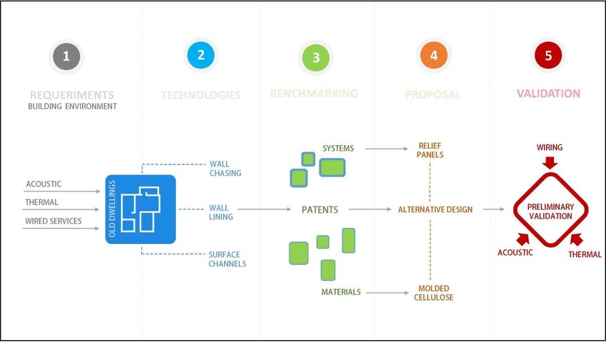
to their folds and gaps;
(5) No concerns about reducing environmental impact are addressed;
(6) There is no consensus about where to fix sockets and switches: onboard or on the
frame;
Sustainability 2021, 13, 4643 (7) There does not seem to be the same interest in guaranteeing access to installations in
6 of 18
the selected solutions;
(8) There is marked conflict between the stiffness of the walls and the flexibility of the
wiring;
(9) Solutions do not seem to consider in general the opportunities presented by the wall
(9) Solutions do not seem to consider in general the opportunities presented by the wall
lining in combination with a previous masonry wall;
lining in combination with a previous masonry wall;
(10) The proposed innovation does not, in general, involve the board but rather the
(10) The proposed innovation does not, in general, involve the board but rather the rela-
relationship between the metal profiles and the electrical wiring;
tionship between the metal profiles and the electrical wiring;
(11) Most of the solutions present the primacy of the upright profiles, and only some raise
(11) Most of the solutions present the primacy of the upright profiles, and only some
the possibility of prefabricating all the panels in the workshop.
raise the possibility of prefabricating all the panels in the workshop.
Sustainability
Sustainability2021, 13,13,
2021, x FOR PEER
x FOR REVIEW
PEER REVIEW 7 7ofof19
Figure 3. The patent [15] is designed to resolve the conflict of passage between the profile of19the
partition
Figure 3.and
Thethe layout
patent [15]ofisthe ducts. Reprinted
designed to resolve from Nelson,
the conflict ofJ.A.and
passagePritchard, M.J.profile
between the (1997).of the
partition and the layout of the ducts. Reprinted from Nelson, J.A.and Pritchard, M.J. (1997).
Figure 4. The patent [16] is designed to resolve the conflict of passage between partitions with high
Figure
Figure4.4.The
Thepatent
patent[16]
[16]isisdesignedto
designedtoresolve
resolvethe
theconflict
conflictofofpassage
passagebetween
betweenpartitions
partitionswith
withhigh
high
ductduct
duct density.
density.
density. Reprinted
Reprinted
Reprinted from
fromfrom Reuter,
Reuter,
Reuter, R.E.,
R.E.,
R.E., Bullwinkle,
Bullwinkle,
Bullwinkle, W.C. W.C.
W.C. and and
and Reuter,
Reuter,
Reuter, R.D.
R.D.
R.D. (1999).
(1999).
(1999).
Figure
Figure 5. Patent
5.5.Patent
Figure Patent[17]
[17][17] incorporates
incorporates
incorporates an intermediate
ananintermediate
intermediate panel panel
panel that
that that supports
supports
supports a large
a alarge
large amount
amount
amount of horizontal
ofofhorizontal
horizontal
cabling
cabling arranged
cablingarranged
arrangedononseparate
separate
on tracks,
separatetracks,but
tracks,butatatthe
but at same
the same
the time,
same time,it itcan
time, it support
can support
can control
support controlcomponents
components
control components and
and aa a
and
track
trackchange
change
track system.
changesystem. Reprinted
system.Reprinted from
Reprintedfrom Waalkes,
fromWaalkes, M.;
Waalkes, M.;Pressnell,
Pressnell,
M.; M.;
Pressnell, M.;Slager,
Slager,
M.; M.;
M.;Shields,
Slager, M.;
Shields,
M.; M.;Kane,
Shields, Kane,B.;B.; B.;
M.; Kane,
Christopher,
Christopher, R.;R.;Boyle,
Christopher, Boyle,
R.; D.;
Boyle,D.;Seiber,
Seiber,
D.; C.;C.;Skillman,
Seiber, Skillman,
C.; Skillman,P.;P.;Chang,
P.;Chang,
Chang,J. J.and
J.and Hand,
and Hand, R.R.(2007).
Hand, R.(2007).
(2007).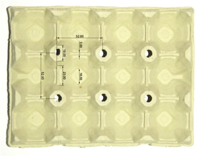
Figure 5. Patent [17] incorporates an intermediate panel that supports a large amount of horizontal
Sustainability 2021, 13, 4643 cabling arranged on separate tracks, but at the same time, it can support control components and
7 of a18
track change system. Reprinted from Waalkes, M.; Pressnell, M.; Slager, M.; Shields, M.; Kane, B.;
Christopher, R.; Boyle, D.; Seiber, C.; Skillman, P.; Chang, J. and Hand, R. (2007).
Sustainability
Sustainability 2021,
2021, 13,
13, xx FOR
FOR PEER Figure
Figure6.6.Patent
PEER REVIEW
REVIEW Patent[18]
[18]isisananevolution
evolutionofofthe
theprevious
previouspatent
patent(Figure
(Figure5)5)and
andwas
wasdesigned
designedtotobebemore
more 88 of
of 19
19
easily
easilyremovable
removableoror prefabricated
prefabricated due
dueto to
thethe
expansive leg leg
expansive system. Reprinted
system. fromfrom
Reprinted Parshad, D.; D.;
Parshad,
Woronecki,
Woronecki,P.P.and
andLiu,
Liu,I.I.(2011).
(2011).
7. Patent
Figure 7.
Figure
Figure Patent[19]
7. Patent [19]isis
[19] isdesigned
designed
designedto to
have
to cable
have
have channels
cable
cable that that
channels
channels do not
doprotrude
that do not from the
not protrude
protrude plane
from
from theofplane
the the of the
plane of the
partition
partition and can be accessed. Reprinted from Wild, R.L. (2001).
partition and
and can
can be
be accessed.
accessed. Reprinted
Reprinted from
from Wild,
Wild, R.L.
R.L. (2001).
(2001).
Figure 8. Patent [20] is designed to have a wiring support panel made from modular pieces that can
Figure
Figure 8.
8. Patent
Patent
be paneled. [20]
[20] is
Reprinted is designed
designed
from to
to have
have
MacDonald, aa wiring
D.B.; wiring support
S.E. andpanel
support
Sanders, panel madeJ.R.from
made
Dykstra, from modular
modular pieces
(2002). pieces that
that can
can
be paneled. Reprinted from MacDonald, D.B.; Sanders, S.E. and Dykstra, J.R.
be paneled. Reprinted from MacDonald, D.B.; Sanders, S.E. and Dykstra, J.R. (2002). (2002).
Sustainability 2021, 13, 4643 8 of 18
Figure 8. Patent [20] is designed to have a wiring support panel made from modular pieces that can
be paneled. Reprinted from MacDonald, D.B.; Sanders, S.E. and Dykstra, J.R. (2002).
Figure
Figure 9. Development of
9. Development ofboth
bothpatents
patents[21,22]
[21,22]was
wasperfected
perfectedinin later
later years,
years, keeping
keeping thethe support
support
Sustainability 2021, 13, x FOR PEER REVIEW
system
system on the ground
Sustainability 2021, 13, x FOR PEER REVIEW ground but
butimproving
improvingthe
theassembly
assemblyand
andpaneling
paneling system
system to to bring
bring it closer
it closer to the
to the ef-9 of 19
ficiency ofofoffice
efficiency officesystems.
systems.Reprinted
Reprintedfrom
fromParshad,
Parshad,D.;
D.;Edwards,
Edwards,J.R.;
J.R.;Woronecki,
Woronecki, P. (2013)
(2013) and
and Liu,
Liu,
I.; Parshad, D.; Woronecki, P. (2013).
I.; Parshad, D.; Woronecki, P. (2013).
Figure 10.10.
Figure Patent
Patent[23]
[23]is
is designed
designed totomake
make the
the solution
solution more
more specific
specific to theto the market,
office office market, as furni-
as furniture
Figure
ture and
and 10. Patent
partitions
partitions form[23]
form isandesigned towhole.
integrated
an integrated whole. make thefrom
solution
Reprinted
Reprinted more
from
Henriott, specific
Henriott,
J.M.; J.M.;to
Metcalf, the(2011).
office
Metcalf,
K.E. K.E.market,
(2011). as f
ture and partitions form an integrated whole. Reprinted from Henriott, J.M.; Metcalf, K.E. (2
Figure 11. Patent [24] is designed to facilitate access to wired installations through a system of
Figure 11. Patent
modular panels [24]
that is designed
integrate to facilitate
control access toaccessories.
and connection wired installations through
These panels a system
are joined by aof
modular
hangingpanels that
system. integrate
Reprinted control
from Bates,and
M.; connection accessories.
Boyce, A.J.; Kang, TheseM.J.;
C.M.; Katje, panels areS.R.;
Lyons, joined by a
Porter,
hanging system. J.D.;
K.E.; Roetman, Reprinted
Sellers, from Bates, G.D.
P.L.; Zaccai, M.; Boyce,
(2011). A.J.; Kang, C.M.; Katje, M.J.; Lyons, S.R.; Porter,
Figure 11. Patent [24] is designed to facilitate access to wired installations through a system o
K.E.; Roetman, J.D.; Sellers, P.L.; Zaccai, G.D. (2011).
modular panels that integrate control and connection accessories. These panels are joined by
hanging system. Reprinted from Bates, M.; Boyce, A.J.; Kang, C.M.; Katje, M.J.; Lyons, S.R.; P
K.E.; Roetman, J.D.; Sellers, P.L.; Zaccai, G.D. (2011).
Figure 11. Patent [24] is designed to facilitate access to wired installations through a system o
Figure 11.
modular Patent
panels that[24] is designed
integrate to facilitate
control access to
and connection wired installations
accessories. through
These panels a system
are joined by
modular panels that integrate control and connection accessories. These panels
hanging system. Reprinted from Bates, M.; Boyce, A.J.; Kang, C.M.; Katje, M.J.; Lyons, are joined
S.R.; b
P
Sustainability 2021, 13, 4643 hanging
K.E.; system.
Roetman, Reprinted
J.D.; fromZaccai,
Sellers, P.L.; Bates, G.D.
M.; Boyce,
(2011).A.J.; Kang, C.M.; Katje, M.J.;9Lyons,
of 18 S.R.;
K.E.; Roetman, J.D.; Sellers, P.L.; Zaccai, G.D. (2011).
Figure 12. Patent [25] is designed to develop a partition from laminated wood profiles. Prop
Figure 12. Patent [25] is designed to develop a partition from laminated wood profiles. Properly
Figure
planned 12. Patentshould
incisions [25] is designed to develop
facilitate the passageaofpartition from laminated
cable housing wood profiles.
without weakening Pro
the parti
planned incisions should facilitate the passage of cable housing without weakening the partition.
planned
Reprinted incisions should facilitate the passage of cable housing without weakening the par
Reprintedfrom Baier,
from Baier, H.H. (2012).
(2012).
Reprinted from Baier, H. (2012).
Figure 13. Patent [26] is designed to develop an aggregate and freestanding panel to accommodate
Figure
all the13. Patent
elements of a[26] is installation
wired designed thatto develop an aggregate
can be completely and freestanding
prefabricated in a workshop. panel to accomm
Reprinted
allFigure
the 13. Patent
elements of a[26] is
wired designed to
installation
from Sutton, T.A.; Bodkins, N.J. (2012).
develop
that canan
be aggregate
completely and freestanding
prefabricated inpanel
a to accom
workshop. R
all the elements of a wired installation
printed from Sutton, T.A.; Bodkins, N.J. (2012). that can be completely prefabricated in a workshop.
printed In the
fromindustrial market,
Sutton, T.A.; some recent
Bodkins, products for wall cladding make interesting
N.J. (2012).
contributions and point in various directions for future evolution:
(1) Internal panels that continuously support the finished board, such as NATURBO® [27];
(2) Lighter internal panels with great ease of cutting on-site, Schlüter® KERDI-BOARD [28];
(3) Systems with a modular presentation, in which the combination of two liners gener-
ates a partition wall AABYAA® [29].
Internal molded panels should solve the issues of contact with the laminate base
gypsum board and contact with the supporting wall. The alternative system is wall lining
of the type called semi-direct. In this case [30], the current standard specifies the type of
fixings and the distances between them, but assuming that the connection between the
laminate base gypsum board and the supporting wall is made through a metal profile.
As a result of financial support for the VALTEC09-2-0032 research project, some
concept tests could be carried out with real market procedures in a pilot study to delimit
aspects specific to the implementation, which are not well enough represented in technical
literature. These include resource consumption, yields and drying times.
The consulted industrial references indicate that the challenge has not been satisfacto-
rily resolved to date, and there are several unexplored avenues of innovation that could be
of use in the challenge presented here.
3. Objectives of the Investigation
Considering the state of the issue, it is clear that there is no efficient solution for
home wiring refurbishment from an industrial and environmental point of view. Because
of technical and social needs, the current technical solutions for wall lining need to be
reconsidered and redesigned to include the requirements listed below.
Sustainability 2021, 13, 4643                                                                                                     10 of 18

                                           Before on-site works:
                                     1.    Time, cost and quality adjustments, due to increasing industrialization and modulation;
                                     2.    A reduction in environmental impact through using recycled materials.
                                           During on-site works:
                                     3.    A reduction in run time and low waste generation through using small modules that
                                           are stackable and light;
                                     4.    Facilitation of work processes through using materials that are easily cut, nailed,
                                           screwed, drilled and fixed on the existing support and to each other;
                                     5.    Facilitation of the fitting of wired networks;
                                           After on-site works:
                                     6.    Improvement in the final technical quality of the set without altering the initial
                                           architectural appearance: facilitation of the fitting of standard laminate base gypsum
                                           board as a finishing layer;
                                     7.    Facilitation of the fitting of thermal and acoustic insulation products.

                                     4. Methods
                                          To carry out the above objectives, a redesign process (Figure 14) was initiated to define
                                     an alternative to the wall lining air chamber based on:
                                     (1)   Replacing the differentiated support elements (uprights) with a continuous structure
    Sustainability 2021, 13, x FOR PEER REVIEW                                                                               11 of 19
                                           should reduce the thickness of the gypsum board that finally coats the liner;
                                     (2) Looking for a recycling material with low environmental impact to materialize this
                                           continuous structure;
                                            The redesign
                                     (3) Providing     thisprocess was structure
                                                            continuous developedwith
                                                                                  as part
                                                                                      reliefofgives
                                                                                               a university
                                                                                                    it greaterproduct
                                                                                                               rigiditydevelopment
                                                                                                                        and the ability
                                       workshop   [31]  in which students and teachers are   trained
                                           to insert the wiring without needing to use point fixings. and collaborate  in this disci-
                                       pline through the design learning processes.

                                      Figure 14. Product
                                              Figure 14. development methodology.
                                                         Product development methodology.

                                      4.1. The
                                           Find redesign
                                                 a Materialprocess
                                                            That Meets
                                                                    wasObjectives
                                                                         developed2, 4 &
                                                                                       as7part of a university product development
                                     workshop     [31] in which
                                            The process          students
                                                          involved        and
                                                                    looking forteachers
                                                                                a materialarethat
                                                                                              trained  and
                                                                                                  can be   collaborate
                                                                                                         formed         in thiswith
                                                                                                                 into a panel  discipline
                                                                                                                                    re-
                                     through
                                      lief thatthe  design
                                                is also     learning Polymers
                                                        machinable.   processes.are the best-positioned materials today in terms of
                                      variety, cost, precision and experience in the electrical sector. However, as they have a
                                      recognized environmental impact,an alternative solution was sought that was organ-
                                      ic,reduced the environmental impact and recovered some industrial wasteand its recy-
                                      cling. This research process was initiated at our own university to establish development
Sustainability 2021, 13, 4643 11 of 18
4.1. Find a Material That Meets Objectives 2, 4 & 7
The process involved looking for a material that can be formed into a panel with relief
that is also machinable. Polymers are the best-positioned materials today in terms of variety,
cost, precision and experience in the electrical sector. However, as they have a recognized
environmental impact, an alternative solution was sought that was organic, reduced the
environmental impact and recovered some industrial waste and its recycling. This research
process was initiated at our own university to establish development synergies.
In this case, cellulose pulp is a good candidate. Recent innovations have been made
in this family of recycled materials that have updated mechanical and waterproofing
performance [32,33]. The authors have focused on Biprocel, a new material developed by a
company that emerged from the Universitat Politècnica de Catalunya (UPC) as a result of
a research project on the transformation of paper factory waste. In 2011, the patent was
published internationally, and the project became a spinoff.
Biprocel is a suitable material [34] for this application because it can be molded easily
to offer the right geometric surface to carry out its function as an interface panel between
laminate base gypsum board lining and a wired network, and it can be obtained in different
densities according to the applications.
This material reduces the environmental impact because it is made from recovered
fiber waste in paper factories and self-recovery of construction companies’ on-site residue.
This new material recovers residues that are considered non-repellent (inks, loads and
glues), and all the water used in their processing is recyclable. Sometime ago, a joint
research development project [35] explored the possibility of applying cellulose pulp
molding technologies to building materials.
4.2. Find a Molded Form That Meets Objectives 1, 3, 5 & 6
To define realistically what the thickness goal of the alternative system should be for
wall lining interior partitions, it was noticed that this dimension was directly established by
the thickness of cast sockets and switch mechanisms manufactured by the electrical indus-
try, which are usually 50 mm. If the thickness of the alternative system fits 50 mm, it will
be easy to use the innovation in the building process without extra works for adaptations.
To explore what might be the most appropriate way to meet the requirements and
at the same time move closer to the current possibilities of the pulp molding technique,
the search was repeated in the patent databases mentioned above. A total of 22 patents
covering the period from 1949 to 2013 were analyzed. The research was completed with
the study of samples that are currently present in the retail market for food packaging and
household appliances (Figures 15 and 16).
From the analysis of these sources, the following findings were collected:
(1) The thickness of the cellulose pulp moldings is similar to that of cardboard paper and
does not exceed 1mm, so it acquires its rigidity due to the double relief on both sides
obtained from a central core. This central core also has slight ribbing;
(2) The relief, conical trunks or prismatic trunks have a slight inclination to facilitate demolding;
(3) At its edges, it is always additionally reinforced by bending to prevent perimeter tearing;
(4) Most of the moldings are stackable, which significantly reduces their volume and
deterioration during transport and storage processes;
(5) The thickness achieved is in most cases around the 50 mm objective set;
(6) Modular molded parts can be obtained, but it is also possible to obtain custom-made
parts for special uses;
(7) Molded cellulose is compatible with wet sprayed cellulose and injected cellulose wool
used in thermal insulation applications in enclosed air chambers;
(8) All collected patents and specimens feature flat ends on both reliefs to facilitate
support on flat surfaces;
(9) There are no sharp edges to avoid damage to the items themselves and to people who
handle them without gloves;
(10) It is not difficult to obtain polygonal or curved surfaces;wall lining interior partitions, it was noticed that this dimension was directly estab-
wall lining interior partitions, it was noticed that this dimension was directly estab-
lishedby the thickness of cast sockets and switch mechanisms manufactured by the elec-
lishedby the thickness of cast sockets and switch mechanisms manufactured by the elec-
trical industry, which are usually 50 mm. If the thickness of the alternative system fits 50
trical industry, which are usually 50 mm. If the thickness of the alternative system fits 50
mm, it will be easy to use the innovation in the building process without extra works for
mm, it will be easy to use the innovation in the building process without extra works for
adaptations.
Sustainability 2021, 13, 4643 adaptations. 12 of 18
To explore what might be the most appropriate way to meet the requirements and at
To explore what might be the most appropriate way to meet the requirements and at
the same time move closer to the current possibilities of the pulp molding technique, the
the same time move closer to the current possibilities of the pulp molding technique, the
search was repeated in the patent databases mentioned above. A total of 22 patents cov-
search was repeated in the patent databases mentioned above. A total of 22 patents cov-
ering (11)
the period from 1949between
A lateral to 2013 were analyzed. The research was completed with the
ering the period from union
1949 to 2013 were moldings
analyzed.is not
Theprovided;
research was completed with the
study of samples ofthat are currently present in the
toretail market foran
food packaging andimpor-
study of(12) Mostthat
samples the
aremoldings
currentlyrequire theinneed
present generate
the retail marketboxes,
for foodaspect that isand
packaging not
household tant
appliances
for use (Figures
in 15 and 16).
buildings.
household appliances (Figures 15 and 16).
FigureFigure
15. Both Both patents
15.patents [36,37][36,37] are designed
are designed to generate
to generate a molded
a molded geometry
geometry to contain
to contain eggs
eggs in in a safe
asafe
Figure 15. Both patents [36,37] are designed to generate a molded geometry to contain eggs in asafe
upright
upright position.
position. Reprinted
Reprinted from Schechter,
from Schechter, A. (1967).
A. (1967). and Grant,
and Grant, J.R. (1953).
J.R. (1953).
upright position. Reprinted from Schechter, A. (1967). and Grant, J.R. (1953).
Figure 16. Ground, lateral and sectional view of a commercially molded cellulose plate for egg storage.
Figure(source:
16. Ground, lateral and sectional view of a commercially molded cellulose plate for egg
authors).
Figure 16. Ground, lateral and sectional view of a commercially molded cellulose plate for egg
storage.
storage.
5. Development of the Molded Panel
From Atthethis
analysis
stage of
of these sources, of
development thethe
following findings
panel,findings
the were collected:
mainwere
geometric characteristics need to
From the analysis of these sources, the following collected:
be defined
(1) The to adapt
thickness of the to all the interior
cellulose renovation
pulp moldings work. to that of cardboard paper
is similar
(1) The thickness of the cellulose pulp moldings is similar to that of cardboard paper
and does not exceed 1mm, so it acquires its rigidity due to the double relief on both
and5.1.
does not exceed and1mm, so
of it acquires its rigidity due to the double relief on both
sidesModulation
obtained from Relief
a centralthe Panels
core. This central core also has slight ribbing;
sides obtained from a central core. This central core also has slight ribbing;
A previous square modulation of 60 × 60 cm is adopted because it is the common
format of building products designed for interior spaces. The molded panels’ feature relief
is formed of two types:
(1) Outputs to support the laminated base gypsum board (LGB);
(2) Channels between the outputs to facilitate the insertion and anchorage of electrical
elements. Channels of diverse width are provided: channels for wiring as described
(Table 2), channels for electrical control boxes (superior and inferior) and channels for
electrical connection and junction boxes (Figure 17).Sustainability 2021, 13, 4643 13 of 18
Sustainability 2021, 13, x FOR PEER REVIEW 14 of 19
Sustainability 2021, 13, x FOR PEER REVIEW 14 of 19
Figure 17. Overall view of the panel: layout of outputs and related channels. (source: authors).
5.2. Jointing of the Panels
Figure 17.Overall view of the panel: layout of outputs and related channels.
To apply these panels to the surface of the previous interior partition wall, it may be
advisable to start with whole panels from one corner because this will produce cutting
waste only at the opposite end and close to the door openings (Figure 18). The joint between
contiguous
Figure 17.Overall panels
view of is
thecreated by overlapping
panel: layout theirrelated
of outputs and borders.
channels.
Figure 18. Overall view of a case application of panels on a wall.The position of the electrical mechanisms and the cutting
border areas are also marked in color.
5.3. Insertion of Electrical Control and Junction Boxes
Figure
Figure 18.
18. Overall
Overall view
view of
of aa case
case application of
Electrical of
application panels on
control
panels on aa wall.
boxes wall.The
Theposition
(switches andof
position the
the electrical
ofsockets) must
electrical mechanisms and
be inserted
mechanisms the
the cutting
and tightly into the
cutting
border areas are also markedmolded
in color. panel, without the need for any machining (Figure 19):
border areas are also marked in color.
5.3. Insertion of Electrical Control and Junction Boxes
Electrical control boxes (switches and sockets) must be inserted tightly into the
molded panel, without the need for any machining (Figure 19):Sustainability 2021, 13, 4643 14 of 18
Sustainability 2021, 13, x FOR PEER REVIEW 15 of 19
5.3. Insertion
(1) 100
Sustainability 2021, 13, x FOR PEER REVIEW mmof channel
Electricalwidth
Controlfor andinsertion
Junction of
Boxes
junction electrical boxes located from 15 of the
19
lower end
Electrical of theboxes
control module;
(switches and sockets) must be inserted tightly into the molded
(2) 74without
panel, mm channel width
the need for insertion
for any machining of(Figure
switches located at 20 cm from the lower end
19):
(1) of the
100 mm module;
(1) 100 mm channel
channelwidth
widthforforinsertion of junction
insertion electrical
of junction boxesboxes
electrical located from the
located fromlower
the
(3) end
74 mmof channel
the width for the insertion of socket boxes, located from the lower end of
module;
lower end of the module;
(2) themm
74 module;
channel width
(2) 74 mm channel width for
for insertion
insertionofofswitches
switcheslocated
locatedatat2020
cmcmfrom
fromthethe
lower endend
lower of
(4) the
Themodule;
casket for fitting the mechanisms of the electrical installation is in the perimeter
of the module;
(3) relief
74 mmofchannel
the areawidth
channel designed
for the
theto insertion
accommodate it. boxes, located from the lower end of
of socket
socket
(3) 74 mm width for insertion of boxes, located from the lower end of
the module;
the module;
(4) The casket for fitting the mechanisms of the electrical installation is in the perimeter
(4) The casket for fitting the mechanisms of the electrical installation is in the perimeter
relief of the area designed to accommodate it.
relief of the area designed to accommodate it.
Figure 19. Perspective view of the location and dimensions of the switches.
5.4. Location of Wires
FigureIn
Figure 19.most
19.
low-voltage
Perspective
Perspective view ofelectrical
view of the
codes
the location
location and[12],
and
the cables
dimensions
dimensions of
must
of the
be housed inside conduits
the switches.
switches.
in a way that facilitates their present installation and the future passage of additional ca-
5.4. Location
blesLocation of Wires
in the future.
5.4. of Wires
In
(1) In most
The low-voltage
basic electrical
outputs are 5 cm codes
in [12], theand
diameter cables
aremust be housed
placed inside vertical
conduitsand
in
most low-voltage electrical codes [12], the cables must beinhoused
diagonal,
inside conduits
a wayhorizontal
that facilitates their present
alignments. installation
In areas where and two the future passage of additional cables
in a way that facilitates their present installation andcontiguous laminated
the future passage base gypsum
of additional ca-
in theboardswill
future. be supported simultaneously, the outputs have an enlarged diameter
bles in the future.
The basic
(Figure outputs are 5 cm in diameter and are placed in diagonal, vertical and
20);
(1) The basic
horizontal outputs are 5 cm in diameter and arelaminated
placed inbase
diagonal, vertical and
(2) In the free spacesIn
alignments. areas
between where
basic two
and contiguous
enlarged outputs, there aregypsum
smallerboardswill
outputs to
horizontal
be supported alignments. In areas where two contiguous laminated base gypsum
facilitatesimultaneously,
the anchorage of the
theoutputs
wiringhave
path.an enlarged diameter (Figure 20);
boardswill be supported simultaneously, the outputs have an enlarged diameter
(Figure 20);
(2) In the free spaces between basic and enlarged outputs, there are smaller outputs to
facilitate the anchorage of the wiring path.
Figure20.
Figure 20.Detailed
Detailedview
viewof
ofthe
theinsertion
insertionof
ofaacable
cable(red)
(red)in
inthe
thedifferent
differentoutputs.
outputs.
5.5. Fixing
In the Laminate Base
free spaces Gypsumbasic
between Boardand enlarged outputs, there are smaller outputs to
facilitate the anchorage of the wiring
Once the electrical wiring workwas path. carried out and supervised, the laminate base
Figure 20. Detailed view of the insertion of a cable (red) in the different outputs.
gypsum board can be installed using the usual screwdrivertechniques. For this work to
be easy
5.5. Fixingand tight, the
Laminate Basemodulation of the outputs must coincide with the standard mod-
Gypsum Board
Once the electrical wiring workwas carried out and supervised, the laminate base
gypsum board can be installed using the usual screwdrivertechniques. For this work to
be easy and tight, the modulation of the outputs must coincide with the standard mod-Sustainability 2021, 13, 4643 15 of 18
5.5. Fixing Laminate Base Gypsum Board
ainability 2021, 13, x FOR PEER REVIEW Once the electrical wiring work was carried out and supervised, 16 of laminate
19
nability 2021, 13, x FOR PEER REVIEW 16 the
of 19 base
gypsum board can be installed using the usual screw driver techniques. For this work
to be easy and tight, the modulation of the outputs must coincide with the standard
ulation themodulation
ulationofofthe laminatebase
laminate
of the
base gypsum
laminate
gypsum base gypsum
board(Figure
board(Figure
board(Figure
21):line
21): line alignmentof21):
alignment
line alignment
ofenlarged
enlarged outputs of enlarged
outputs
(10cm
cmdiameter)outputs
diameter)ininthe(10 cm
thecenter diameter)
centerofofthe in the
themodule, center
module,with of
withan the module,
aninterstice with
intersticebetween an interstice
betweenoutputs
outputsofofbetween
1cm. outputs of
(10 1cm.
Theprototype 1cm.
prototypedesign The prototype
designevolves design
evolvestotoadapt
adapttheevolves to
theprevious adapt
previousconceptthe previous
conceptdesign concept
designtotopulp celluloseto
design
pulpcellulose pulp cellulose
in-
The in-
industry
dustryabilities.
abilities. abilities. Ageometrical
preliminarymodel
geometrical model wasto3D printed to test with different
dustry AApreliminary
preliminary geometrical model was3D
was 3D printed
printed test
to test withdifferent
with different
cableclasses cable
classes(Figure classes
(Figure22)
22)the(Figure 22)
thefeasibility the feasibility
feasibilityofofthe
theinsert of the
insertprocess. insert
process. process.
cable
Figure 21. Detailed
Figure 21. Detailed views of solutions adopted in the outputs to support simultaneouslytwo con-
Figure views of solutions
21. Detailed views adopted in the
of solutions outputs
adopted in to
thesupport
outputssimultaneouslytwo contiguous con-
to support simultaneouslytwo laminated base
gypsum boards.tiguous laminated base gypsum boards.
tiguous laminated base gypsum boards.
Figure 22. Pictures of the first conceptual model. The first prototype wasmade from the polymer by
Figure
Figure 22. 22. Pictures
Pictures of conceptual
of the first the first conceptual model.
model. The first The first prototype
prototype was madewasmade
from thefrom the polymer
polymer by
by 3D printing.
3D printing.
3D printing.
6. Discussion of Preliminary Results
6.6.Discussion
Discussionof ofPreliminary
PreliminaryResultsResults
This preliminary prototype responds to many of the basic premises set for use in
Thispreliminary
This preliminaryprototype
prototyperesponds
respondstotomany many ofthe thebasic
basicpremises
premisesset setfor
foruse
useininthe
the
the refurbishment of building works. of It is a dry process with low environmental impact,
refurbishment ofof building
refurbishment building works.
works. ItIt isis aa dry
dry processwith
processwith low low environmental impact,impact,
lightweight and easy to install, as indicated in detail environmental
in Section 3.
lightweightand
lightweight andeasy
easytotoinstall,
install, asindicated
indicatedinindetaildetailininSection
Section3.3.
After this firstasstep, we must continue to advance to address the following challenges
After this first
After thisoffirst step,we
step,we must
must continue
continue to
to advance
advance toto addressthe
address thefollowing
followingchallenges
challenges
any development in the construction sector: first, proceed to adjust the parameters of
of any development
of any development in the construction sector: first, proceed to adjust the parameters of
strength,indurability
the construction
and safety,sector:
whichfirst, proceed
will ensuretothe adjust theand
density parameters
stability ofof the material;
strength, durability
strength, durability and safety, which will ensure the density and stability of the material;
second,and safety,towhich
proceed adjustwill
the ensure the density
parameters in a way and stability
that of with
is in line the material;
the habits and prefer-
second,proceed
second, proceedtotoadjust
adjustthe theparameters
parameters inaaway waythatthatisisininline
linewiththe
withthehabits
habitsand
andpref-
pref-
ences of workers in the sector,inincluding wall lining professionals and wiring professionals.
erences of workers
erences of workers in the sector, includingwall lining professionals and wiring profes-
A thirdinaspect
the sector, includingwall
is to survey electricallining professionals
component and wiring
manufacturers profes- whether this
to validate
sionals. AA third
sionals. third aspect isis
new aspect
support istoto survey
an survey electrical
opportunity electrical component
component
to incorporate manufacturers
manufacturers
greater toto validate
flexibility into validate
this subsector.
whether this new support is an opportunity to incorporate greater
whether this new support is an opportunity to incorporate greater flexibility into this flexibility into this
subsector.
subsector.
7.7.Future
FutureChallenges
Challenges
Afterthe
After thesatisfactory
satisfactorydevelopment
developmentofofthis
thispreliminary
preliminaryproposal,
proposal,thenext
thenextchallenges
challenges
need to be defined:
need to be defined:Sustainability 2021, 13, 4643 16 of 18
7. Future Challenges
After the satisfactory development of this preliminary proposal, the next challenges
need to be defined:
(1) Guarantee the performance of fixing anchors between the laminated base gypsum
board and the molded panel and between the molded panel and the pre-existing wall;
(2) Facilitate the mechanization and manipulation of the molded panel with single tools
to facilitate insert connection and junction boxes of the wired installation;
(3) This molded panel can complement specific insulating materials that can also be
derived from cellulose fiber. Non-agglomerated cellulose fiber is a type of thermal
and acoustic insulation. It can be applied either blown dry or sprayed wet. It is
essential to ensure the proper performance of the molded panel in contact with
thermal insulation of fiber cellulose that is directly projected on the backside of the
molded panel;
(4) Assessment of using boric salts to give fire retardant, fungicidal and insecticidal
properties to the panel;
(5) Adjustment of the thickness of the molded layer of cellulose fibers to ensure medium-
term dimensional stability;
(6) Adaption of the molded panel design to water supply ducts.
8. Conclusions
(1) New social, technical and environmental challenges force current construction prod-
ucts to evolve to reap benefits on these three fronts. The knowledge acquired in the
past decades will serve as a basis for redefining current products and improving
their suitability;
(2) The product design methodology can benefit the construction sector, especially in the
interior rehabilitation of homes that are usually slower, more expensive and with a
higher environmental impact;
(3) This research contributes to improving the applications of molded panels designed
for the refurbishment and using recycled cellulose fibers in the building industry;
(4) The possibility of designing reliefs for every specific purpose is an opportunity for
the future integration of home services and building elements and reducing mutual
disturbance in various situations;
(5) The authors are confident that small but extensive technical problems linked to
improving interior building quality, such as the one raised here, will gradually emerge.
These challenges are an opportunity for co-design based on better use of existing
industrial potential.
Author Contributions: Conceptualization, R.S.-F. and J.-L.Z.-M.; methodology, R.S.-F. and J.-L.Z.-M.;
validation, R.S.-F. and J.-L.Z.-M.; formal analysis, R.S.-F. and J.-L.Z.-M.; investigation, R.S.-F. and
J.-L.Z.-M.; resources, R.S.-F. and J.-L.Z.-M.; writing—original draft preparation, R.S.-F. and J.-L.Z.-M.;
writing—review and editing, R.S.-F. and J.-L.Z.-M.; visualization, R.S.-F. and J.-L.Z.-M.; supervision,
R.S.-F. and J.-L.Z.-M.; project administration, R.S.-F. and J.-L.Z.-M.; funding acquisition, R.S.-F. and
J.-L.Z.-M. All authors have read and agreed to the published version of the manuscript.
Funding: This development was funded in part by CIDEM of the Generalitat de Catalunya in the
call VALTEC09-2-0032 Innovative procedure for the hidden layout of wired installations in interior partitions.
The authors are grateful for the collaboration of the company Biprocel in developing this research. The
company has addressed all the issues raised and has shown full readiness to continue development.
Institutional Review Board Statement: Ethical review and approval were waived for this study,
due to the fact that our technical university has not ethic committee at the time this research
was developed.
Informed Consent Statement: Informed consent was obtained from all subjects involved in the study.
Data Availability Statement: Data supporting reported results can be found on: https://www.
tesisenred.net/handle/10803/458877#page=1 (accessed on 19 April 2021).Sustainability 2021, 13, 4643 17 of 18
Conflicts of Interest: The authors declare no conflict of interest.
References
1. Santangelo, A.; Tondelli, S. Occupant behaviour and building renovation of the social housing stock: Current and future
challenges. Energy Build. 2017, 145, 276–283. [CrossRef]
2. Gohardani, N.; Björk, F. Sustainable refurbishment in building technology. Smart Sustain. Built Environ. 2012, 1, 241–252.
[CrossRef]
3. European Commission. Communication from de Commission Europe 2020: A Strategy for Smart, Sustainable and Inclusive Growth;
European Commission: Brussels, Belgium, 2020; Available online: https://ec.europa.eu/eip/ageing/file/225/download_en%
3Ftoken=Ff9OHs4J (accessed on 7 April 2021).
4. Holck Sandberg, N.; Sartori, I.; Richard Dawson, O.; Dascalaki, E.; Dimitriou, S.; Vimm-r, T.; Filippidou, F.; Stegnar, G.;
ŠijanecZavrl, M.; Brattebø, H. Dynamic building stock modelling: Application to 11 European countries to support the energy
efficiency and retrofit ambitions of the EU. Energy Build. 2016, 132, 26–38. [CrossRef]
5. Report on Access to Decent and Affordable Housing for All (2019/2187(INI)). Available online: https://www.europarl.europa.
eu/doceo/document/A-9-2020-0247_EN.html (accessed on 7 April 2021).
6. White Paper Residential Electrical Safety How to Ensure Progress Forum for European Electrical Safety (Feeds). May 2017.
Available online: https://www.iut.nu/wp-content/uploads/2018/06/Feeds-Forum-White-Paper-2017.pdf (accessed on 7
April 2021).
7. Gasca, J.C.T.; de las Casas Ayala, J.M.; Frutos, C.B. Diseño y ubicación de los mecanismos eléctricos en las viviendas: Análisis
y soluciones. Segur. y Medio Ambiente 2010, 120, 30–31. Available online: https://documentacion.fundacionmapfre.org/
documentacion/publico/i18n/catalogo_imagenes/grupo.do?path=1062520 (accessed on 7 April 2021).
8. International Electrotechnical Commission IEC 60364-8-1:2019 IEC 60364-5-52:2009 Low-Voltage Electrical Installations-Part 5-52:
Selection and Erection of Electrical Equipment-Wiring Systems. Available online: https://webstore.iec.ch/publication/1878
(accessed on 7 April 2021).
9. CEC. Catálogo de Elementos Constructivos del CTE. 2010. Available online: https://www.codigotecnico.org/pdf/Programas/
CEC/CAT-EC-v06.3_marzo_10.pdf (accessed on 7 April 2021).
10. NHBC. National House Building Council Standards. 2021. Available online: https://nhbc-standards.co.uk/9-finishes/9-2-wall-
and-ceiling-finishes/9-2-4-dry-lining/ (accessed on 7 April 2021).
11. EC. Manual of Standard Building Specifications. 2011. Available online: https://eeas.europa.eu/archives/docs/business-
tenders/docs/20151209/3-4-annex-4-mit-standard-building-specifications_en.pdf (accessed on 7 April 2021).
12. CSTB. Tests by Product. Available online: https://evaluation.cstb.fr/en/tests/product/doublage-de-mur/ (accessed on 7
April 2021).
13. Hispalam® Large Size Clay Bricks + Drywall Board System. Available online: http://www.hispaplano.com/Uploads/docs/
Informacio%20Basica%2002%2010%2008%20Ingles.pdf (accessed on 7 April 2021).
14. Muralit® Large Size Clay Bicks + Drywall Board System. Available online: https://muralit.es/ (accessed on 7 April 2021).
15. Nelson, J.A.; Pritchard, M.J. Removable Non-Load-Bearing Partitions; Partitions with a Free Upper Edge Modular Coordination
Assembled Using Frames with Infill Panels or Coverings Only; Made-Up of Panels and a Support Structure Incorporating Posts
with Panels and Support Posts, Extending from Floor to Ceiling with Wallboards Attached to the Outer Faces of the Posts, Parallel
to the. Partition. Patent No. EP 0778376 B1, 11 June 1997.
16. Reuter, R.E.; Bullwinkle, W.C.; Reuter, R.D. U.S. Lay-In Wireways for a Space Divider System. Patent 5918433 A, 6 July 1999.
17. Waalkes, M.; Pressnell, M.; Slager, M.; Shields, M.; Kane, B.; Christopher, R.; Boyle, D.; Seiber, C.; Skillman, P.; Chang, J.; et al.
Knock-Down Portable Partition System. U.S. Patent 20070227079 A1, 4 October 2007.
18. Parshad, D.; Woronecki, P.; Liu, I. Office Partition System. U.S. Patent 7975445 B2, 12 July 2011.
19. Wild, R.L. U.S. Transmission Media Patch Panel Modular Cabinetry System. Patent 6322176 B1, 27 November 2001.
20. MacDonald, D.B.; Sanders, S.E.; Dykstra, J.R. U.S. Stacking Connector for Partitions. Patent 6351917 B1, 5 March 2002.
21. Parshad, D.; Edwards, J.R.; Woronecki, P. Electrified Lockable Double Sided Storage Cabinet. U.S. Patent 8387314 B2, 5 March 2013.
22. Liu, I.; Parshad, D.; Woronecki, P. Variable Width Module Office Furniture Partition. U.S. Patent 8534021 B2, 17 September 2013.
23. Henriott, J.M.; Metcalf, K.E. Partition System. U.S. Patent 20110197519 A1, 18 August 2011.
24. Bates, M.; Boyce, A.J.; Kang, C.M.; Katje, M.J.; Lyons, S.R.; Porter, K.E.; Roetman, J.D.; Sellers, P.L.; Zaccai, G.D. Wall Mounted
Assembly. U.S. Patent 20110219706 A1, 15 September 2011.
25. Baier, H. Wandverkleidungsmodul. Patent No. EP 2450500 A2, 9 May 2012.
26. Sutton, T.A.; Bodkins, N.J. Wall-Mounted Modular Accessory System. U.S. Patent 12/713,547, 11 December 2012.
27. NaturboTherm® Wall Heating. Available online: https://www.naturbo.co.uk/wall-heating-system (accessed on 7 April 2021).
28. Schlüter® -KERDI-BOARD. Available online: https://www.kerdi-board.co.uk/ (accessed on 7 April 2021).
29. Aabyaa® SNK 50 KIT. Available online: https://aabyaa.com/wp-content/uploads/2019/07/Manual-SNK50-KIT-AABYAA.pdf
(accessed on 7 April 2021).
30. The Gypsum Construction Handbook. 2009. Available online: http://www.macopa.com/sites/default/files/documentos-
catalogos-manuales/2_gypsum_construction_handbook_usg_ingles.pdf (accessed on 7 April 2021).
31. TOSCA. Available online: https://etsavupc.wixsite.com/tosca/2014-bcn (accessed on 7 April 2021).You can also read


