Theme IV - Understanding Seismicity Catalogs and their Problems
←
→
Page content transcription
If your browser does not render page correctly, please read the page content below
Theme IV - Understanding Seismicity
           Catalogs and their Problems
                   Earthquake Location Accuracy

                   Stephan Husen1 • Jeanne L. Hardebeck2
   1. Swiss Seismological Service, ETH Zurich
   2. United States Geological Survey

                                How to cite this article:
Husen, S., and J.L. Hardebeck (2010), Earthquake location accuracy, Community
Online Resource for Statistical Seismicity Analysis, doi:10.5078/corssa-55815573.
Available at http://www.corssa.org.

                              Document Information:
                     Issue date: 1 September 2010 Version: 1.0
2 www.corssa.org Contents 1 Motivation .................................................................................................................................................. 3 2 Location Techniques ................................................................................................................................... 4 3 Uncertainty and Artifacts .......................................................................................................................... 9 4 Choosing a Catalog, and What to Expect ................................................................................................ 25 5 Summary, Further Reading, Next Steps................................................................................................... 30
Earthquake Location Accuracy                          3

Abstract Earthquake location catalogs are not an exact representation of the true
earthquake locations. They contain random error, for example from errors in the
arrival time picks, as well as systematic biases. The most important source of
systematic errors in earthquake locations is the inherent dependence of earthquake
locations on the assumed seismic velocity structure of the Earth. Random errors
may be accounted for in formal uncertainty estimates, but systematic biases are
not, and they must be considered based on knowledge about how the earthquakes
were located. In this article we discuss earthquake location methods and methods
for estimating formal uncertainties; we consider systematic biases in earthquake
location catalogs; and we give readers guidance on how to identify good-quality
earthquake locations.

1 Motivation

Statistical seismology strives to quantify, test, and understand the spatial-temporal
behavior of earthquakes. However, the spatial-temporal properties of earthquakes
cannot be studied directly; one must instead study the spatial-temporal properties
of earthquake catalogs. The applicability of any particular statistical result to the
real Earth depends in part on the extent to which the utilized catalog accurately
represents the real earthquake properties. Therefore, when undertaking a statistical
study using an earthquake catalog, it is vital to understand the original purpose
and limitations of the catalog and how these limitations may affect the study’s
results.
Consider, for example, the Parkfield segment of the San Andreas Fault, the focus of
many studies (e.g. Bakun et al. 2005), and a location where numerous earthquake
catalogs have been generated for different purposes. Some research goals at
Parkfield depend on characterizing the distances between earthquakes, such as
Rubin and Gillard’s (2000) study of the scaling of the distances between
consecutive events with the magnitude of the first event. These research goals are
best served by earthquake catalogs that have been created with the purpose of
precisely locating the events relative to one another, with less concern about their
absolute position in space. Rubin and Gillard (2000) therefore used a catalog based
on waveform cross-correlation, which uses small shifts in arrival times to precisely
constrain the relative locations of nearby events. Other research goals are
dependent on knowing the absolute locations of earthquakes, a major example
being the SAFOD project’s goal of drilling through the San Andreas at the location
of a repeating earthquake sequence. This requires an earthquake catalog that has
been created with the purpose of accurately determining the absolute locations of
the earthquakes, with less concern about their relative locations. Catalogs based on
careful modeling of the seismic velocity structure at Parkfield (e.g., Zhang et al.
2009) should provide the best absolute locations.
Earthquakes can be located using different techniques ranging from standard
linearized techniques to probabilistic techniques employing direct-searches of the
solution space, from single-event locations to joint multiple-event locations, from
absolute locations to relative locations. Each technique relies on certain
4                                         www.corssa.org

assumptions and has its strengths and weaknesses. Knowing these is important to
understand the limitations of a given earthquake catalog. Catalog earthquake
locations and origin times, like all quantitative data, have uncertainty due to
random errors in the basic observations used to derive them. In addition to random
location errors, earthquake catalogs may include location artifacts and systematic
location biases, which are not reflected in the formal uncertainties provided with
the catalog. The common source of most systematic location errors is the
fundamental problem that estimates of earthquake locations, earthquake origin
times, and the Earth’s seismic velocity structure are inherently coupled. To find the
correct earthquake locations requires the correct velocity structure, which is of
course never exactly known, creating tradeoffs between seismic velocity models and
earthquake parameters.
In this article, we discuss the most commonly used methods for locating
earthquakes, methods for estimating the formal uncertainty representing the
random errors, and common artifacts related to the coupling of earthquake
locations to seismic velocity structure. We present some general “rules of thumb” to
help catalog users identify good quality earthquake locations, and discuss common
issues in local, regional, and global scale catalogs. To assist users in identifying the
appropriate catalog for their particular study, we also discuss the advantages and
disadvantages of catalogs located using single-event and relative-location
techniques.

For this article, we assume that the reader is familiar with seismic waves and
raytracing, such as the material covered in Shearer (1999) or Lay and Wallace
(1995). The reader should also have some familiarity with seismic networks (e.g.,
Lee and Stewart 1981) and geophysical inverse techniques (e.g., Menke 1989,
Tarantola 2005). However, the reader need not be an expert in these fields.

2 Location Techniques

2.1 A coupled, inherently nonlinear problem

An earthquake location specifies the place and time of occurrence of energy release
from a seismic event. In combination with a measure of the size a location provides
a concise description of the most important characteristics of an earthquake. The
location may refer to the earthquake’s epicenter, hypocenter, or centroid, or to
another observed or calculated property of the earthquake that can be spatially or
temporarily localized. An earthquake location can be absolute or relative. An
absolute earthquake location is computed or specified within a fixed, geographic
system and a fixed time base (e.g., Coordinated Universal Time (UTC)); a relative
earthquake location is determined or specified with respect to another spatio-
temporal object (e.g., an earthquake or explosion) which itself may have an
unknown or an uncertain absolute location.
Because earthquakes take place deep in the Earth, their source locations must be
inferred from observations that are recorded at stations located only at one side of
Earthquake Location Accuracy                           5

the earthquake (e.g., at the Earth’s surface). This unfavorable geometry makes the
determination of focal depth often difficult because rays are mainly upgoing (for
local earthquakes) or downgoing (for regional and global earthquakes). An
earthquake location is usually determined by the match or misfit between observed
arrival times of seismic phases at seismic stations, and predictions of these arrival
times for different source locations using a given model of seismic velocities, which
is usually assumed to be a more or less exact representation of the true velocity
structure. Hence, the process of determining an earthquake location can be seen as
an inverse problem with four unknowns (spatial coordinates of the hypocenter
location and origin time). The location that yields the smallest misfit between
observed and predicted arrival times defines the hypocenter location.
For a given model of slowness u(x) (inverse of seismic velocity) and source location
xsrce(x) the arrival time tobs at a station with coordinates xstat(x) can be expressed as
                                                           x stat

                                           t obs = t 0 +     ∫ u(x)ds                (1)
                                                           x srce
where x denotes a vector of spatial coordinates sampling the ray path and t0
denotes origin time. Equation (1) is nonlinear since a change in the source location
changes the ray path over which the integral is computed. Consequently,
earthquake location, which maps arrival times into spatial coordinates and origin
time, is inherently a nonlinear problem. Similarly, a change in the slowness model
u(x) in equation (1) will change arrival time, and, therefore, the hypocenter
location. This is referred to as the coupled hypocenter-velocity problem (Thurber
1992). Since the seismic velocity structure of the Earth is unknown, computation of
a single earthquake location would require determining the slowness model u(x) as
well. This is, of course, impossible and, consequently, the slowness model u(x) is
fixed during the computation of a single earthquake location. The a priori slowness
model may be constrained, for example, by seismic refraction studies. For a large
set of well-constrained earthquakes, however, the coupled hypocenter-velocity
problem can be solved simultaneously (e.g., Kissling 1988, Thurber 1992).

2.2 Linear and nonlinear methods

The earliest, formal earthquake locations using arrival time information from
seismic phases applied direct-search procedures such as graphical methods (Milne
1886) or simple grid-searches (Reid 1910). One of the graphical methods described
by Milne (1886) can be seen as a generalization of using circles based on S-P
arrival times, in which the radii of the circles is given by the corresponding S-P
arrival time. In the 1970s digital computers allowed the use of linearized, iterative
methods based mainly on Geiger’s method (1912). Well-known examples are
Hypo71 (Lee and Lahr 1975) or HYPOELLIPSE (Lahr 1989). Increasing
computing power over the last decades has made large-scale, grid and stochastic
direct searches feasible for earthquake locations (e.g., Sambridge and Kennett
1986, Lomax et al. 2000).

The term “nonlinear” is used ambiguously in geophysics to refer to linearized-
iterated and to nonlinear methods. Here, we use the term to refer to global search
6 www.corssa.org
methods that do not use partial derivatives because linearized methods can also
account for nonlinearity by iterating on the linearized solution.
Linearized methods in earthquake location are based on a Taylor series expansion
of equation (1) around some prior estimate (or guess). Using only the first two
terms of the Taylor series a linear relationship for arrival time is obtained. By
combining all available arrival time observations for a single earthquake location a
vector-matrix equation in the form
Ax = d (2)
can be obtained, in which matrix A relates the adjustments of the hypocentral
parameters (vector x) to the vector d of misfits. Equation (2) can be solved using
standard linear algebraic methods (Menke 1989). Since the original earthquake
location problem is nonlinear, the linearized method needs to be iterated by using
the result of the previous step as prior estimate for the next iteration until some
pre-defined convergence criteria is met. Linearized methods produce a single, best-
fit hypocenter and origin time location, and associated, linearly-estimated
uncertainties, such as a multi-dimensional, normally distributed confidence ellipsoid
centered on the best-fit hypocenter and origin time. This linearized solution,
however, can be a poor representation of the complete solution, and it may be
unstable when the complete solution is irregular or has multiple solutions due to
insufficient or outlier data (e.g., Husen et al. 2003, Lomax et al. 2008). Because
linearized methods do not involve large-scale searches they are computationally fast
and, therefore, often the primary location method in routine earthquake location
for cataloging by seismic networks. On the downside, the solution of linearized
location methods depends on the choice of the prior estimate and, therefore, can be
stuck in a local minimum.
Nonlinear location methods do not require the computation of partial derivatives.
Instead, they are based on deterministic or stochastic searches, which may be
exhaustive or directed and evolutionary. Because of that they are often referred to
as direct-search location methods (Lomax et al. 2008). These methods explore or
map functions that can be simply the root-mean-square (RMS) misfit (Nelson and
Vidale 1990, Husen and Kissling 2001) or more sophisticated likelihood functions
as given, for example, by Lomax et al. (2008). When these searches gather and
retain information globally throughout the prior probability density function (pdf),
they can produce a complete location pdf (Tarantola and Valette 1982, Moser et
al. 1992, Wittlinger et al. 1993, Lomax et al. 2000). Otherwise, these searches may
determine a global or local maximum of the location pdf, or may explore the
neighborhood around these optimal points to locally estimate the pdf and obtain
uncertainty information. The searches used in nonlinear location methods can be
grouped into regular, deterministic searches, directed searches, and importance
sampling (Lomax et al. 2008). Regular deterministic searches include grid-searches,
nested grid-searches, and stochastic, “crude” Monte-Carlo searches (e.g., Sambridge
and Mosegaard 2002). Since they use global and well-distributed sampling of the
model space these searches can estimate the complete location pdf. They are,
however, computationally demanding for problems with many unknowns, large
model spaces or time-consuming forward calculations. Directed, stochastic search
techniques include evolutionary, adaptive global search methods such as the geneticEarthquake Location Accuracy 7 algorithm (e.g., Sambridge and Drijkoningen 1992) and simulated annealing (e.g., Kirkpatrick et al. 1983). Most of these methods were developed for optimization or the identification of some very good solutions, which is equivalent to identifying a global or local maximum of the location pdf. In general, these methods do not explore the prior pdf in a manner that can produce complete, probabilistic solutions to inverse problems. Nevertheless, directed searches are useful for earthquake location because of their efficiency (e.g., Sambridge and Gallagher 1993). Importance sampling tries to choose a sampling density which follows the target function as closely as possible to allow an efficient sampling of the complete, probabilistic solution. The challenge of importance sampling lies in the fact that the target function is unknown, and consequently the optimum importance sampling distribution cannot be determined a priori. The oct-tree importance sampling, for example, has been proven to allow an efficient and reliable sampling of the complete probabilistic solution of earthquake location problem (Lomax et al. 2008, Lomax and Curtis 2001). It uses recursive subdivision and sampling of rectangular cells in a 3-D space to generate a cascade structure of sampled cells, such that the spatial density of the sampled cells follows the target pdf values. This oct-tree structure will have a larger number of smaller cells in areas of higher probability (lower misfit) relative to areas of lower pdf values. Oct-tree sampling has been implemented in the software package NonLinLoc to efficiently compute the complete, probabilistic solution to the earthquake location problem. It is increasingly applied to earthquake location in research and routine operations (e.g., Lomax 2005, Lomax et al. 2001, Husen and Smith 2004, Husen et al. 2003). In summary, two classes of methods exist to solve the earthquake location problem. Iterative, linearized methods solve the problem by the use of partial derivatives and matrix inversion. They have the advantage of being computationally fast and they provide reliable solutions for well-constrained earthquake locations. They have the disadvantage that their solution depends on the quality of the initial guess and they can be unstable for poorly-constrained earthquake locations. Nonlinear or direct-search methods solve the earthquake location problem by sampling either the entire or only parts of the solution space. They have the advantage of obtaining a more complete solution with uncertainties as compared to the linearized methods and do not rely on the quality of initial guess. However, they can be computationally expensive. 2.3 Single-event, joint hypocentral determination, and relative location methods Earthquakes are often located one at a time using arrival times from a set of stations that recorded the event. This procedure is often referred to as single-event location, and both linearized and nonlinear location methods can be used. The resulting location is absolute within a fixed, geographic system and a fixed time base. The location is independent of the location of other earthquakes and depends only on the observed arrival times and the seismic velocities used. Single-event location is usually still the preferred method for locating earthquakes, particular in routine earthquake location, as the underlying theory is reasonably well understood and the computational burden is low.
8                                        www.corssa.org

Instead of locating earthquakes one at a time, a set of earthquakes can be located
jointly. In general, this is referred to as joint hypocenter determination (JHD) (e.g.,
Douglas 1967, Kissling 1988, Pujol 2000). JHD methods are usually linearized
methods as the high dimensionality of the problem makes direct-search solutions
difficult and computationally demanding. Similar to single-event location, JHD uses
arrival times of seismic phases determined at seismic stations and the resulting
locations are absolute. To reduce the effects of errors in the travel time model, JHD
allows the use of static station corrections based either on travel time residuals
(Pujol 1992) or by explicitly treating them as unknowns in the inverse problem
(Kissling 1988). The station correction is a constant time added to all of the
modeled travel-times to that station, and this accounts for unmodeled velocity
structure along the common ray path below the station. The source-specific station
term (SSST) technique replaces the single static correction at each station with
station terms that vary as a function of source location (Richards-Dinger and
Shearer 2000). For large data sets JHD can be used to detect systematic errors
related to arrival time data or station parameters (location and timing) by
investigating station specific travel time distributions or by comparing station
corrections to local geology (e.g., Kissling 1988, Maurer et al. 2010). Although not
strictly considered to be JHD methods, the simultaneous inversion for hypocenters
and seismic velocities, as done in local earthquake tomography (e.g., Thurber 1993)
or for the computation of a minimum 1-D model (Kissling et al. 1994), can be
considered as such. More importantly, only the simultaneous inversion for
hypocenters and seismic velocities is a proper solution to the coupled hypocenter-
velocity problem, as traditional JHD does not allow inverting for seismic velocities.
Consequently, hypocenter locations obtained by JHD can still be affected by
systematic errors due to unmodeled velocity structure.

A set of earthquakes can be located relative to a master event or relative to each
other. The former is usually called master-event location (e.g., Deichmann and
Garcia-Fernandez 1992), whereas the latter is known as double-difference (DD)
earthquake location (e.g., Waldhauser and Ellsworth 2000). The resulting locations
are relative either to a master event in the case of master-event location or to each
other in the case of DD earthquake location. In the case of master-event location,
information on absolute locations depends on the absolute location of the master
event. DD earthquake location can resolve absolute locations but the accuracy
depends on the accuracy to which the true seismic velocities are known, similar to
single-event location (Menke and Schaff 2004). As in JHD, both methods are
linearized as the high dimensionality of the problem makes direct-search solutions
difficult and computationally demanding.
Master-event location uses travel time residuals computed for the master event as
station corrections to locate all other events, the so-called slave events. Least-
square adjustments are computed using the relative travel time residuals. As a
consequence, the relative locations computed this way are a function of travel-time
differences between master and slave events and of the seismic velocity in the
source region. Because the relative travel time residuals are smaller than the
absolute travel time residuals, the improvement in consistency of the relative
locations is mainly due to the fact of adjusting these smaller residuals (Deichmann
and Giardini 2009). Master-event location relies on the assumption that errors in
Earthquake Location Accuracy                         9

the velocity model are the same for observation from two events at the same
station. This assumption is usually valid for event-station distances that are large
compared to inter-event distances. Consequently, master-event location can only be
applied for a set of earthquakes within a restricted volume.
DD earthquake location relates the residual between observed and calculated
differential travel time between two events to the distance between the two events
(Waldhauser and Ellsworth 2000). Using the appropriate slowness vector at the
source and origin time for each event, a system of linear equations in the form
                                         WAm = Wd                                 (3)
can be created, where A defines a matrix of size M x 4N (M, number of double-
difference observations; N, number of events) containing the partial derivatives, d
is the data vector, m is a vector of length 4N containing the changes in hypocentral
parameters, and W is a diagonal matrix to weight each equation. The matrix A is
highly sparse, as each equation links together only two events. If one event is
poorly linked to all other events, matrix A becomes ill conditioned, and the solution
to equation (3) may become numerically unstable. This can be improved by using
only events that are well linked to other events (Waldhauser and Ellsworth 2000).
In general, this can be achieved by only allowing event pairs, which have more
than a minimal number of observations (at least eight since the number of
unknowns for one pair of events is eight).
With the DD method, a network is built in which each event is linked to its nearest
neighbors through travel time differences observed at common stations. It differs
from other JHD methods in that no station corrections are necessary, because
unmodeled velocity structure is directly removed by using double-differences. This
works best if the ray paths from two events to the same station are nearly
identical. Hence, DD earthquake location works best if events are densely
distributed (compared to average station spacing) and observed at a large number
of stations. The strength of DD earthquake location lies in the fact that is uses
travel time differences, which can be measured with a high precision using
waveform cross-correlation methods (e.g., Rowe et al. 2002, Schaff et al. 2004). By
using these cross-correlation methods, uncertainties in determining travel-time
differences are greatly reduced. Theory and tests with synthetic data show that
differential arrival time data also contain information on absolute earthquake
location (Waldhauser and Ellsworth 2000, Wolfe 2002, Menke and Schaff 2004).
Thus, DD earthquake location can resolve, to a certain extent, absolute earthquake
locations. The performance depends, however, also on the knowledge of the true
velocity structures as in the case for single-event earthquake locations (Menke and
Schaff 2004).

3 Uncertainty and Artifacts

Uncertainties in earthquake locations are dominated by three factors (e.g., Pavlis
1986):
   1. measurement errors of seismic arrival times,
   2. modeling errors of calculated travel times,
10 www.corssa.org
3. nonlinearity of the earthquake location problem.
The latter is only relevant for linearized, least square solutions; direct-search
methods (as discussed in section 2.2) do not require linearization of the earthquake
location problem, and as such they are not affected by errors due to nonlinearity.
The other two types of errors are relevant for linearized and direct-search methods.
Measurement errors of arrival times are always present and stem from a number of
sources, including signal-to-noise ratio and dominant frequency of the arriving
phase. These errors lead to a relative location scatter around the true earthquake
location. Hence, they define the precision of an earthquake location. In the
earthquake location problem they can be treated from a purely statistical point of
view to derive the well-known error ellipsoids, as described in section 3.1.
Therefore, we will refer to these errors as formal errors of the earthquake location
problem. Modeling errors of calculated travel times are mostly dominated by the
quality of the seismic velocity model used to calculate them; the precision of the
method used to calculate the travel times for a given velocity model plays only a
minor role. It is well known that modeling errors of calculated travel times lead to
systematic biases in earthquake location (e.g., Jordan and Sverdrup 1981, Thurber
1992, Billings et al. 1994a). Hence, these errors define the accuracy of an
earthquake location. Proper handling of modeling errors of calculated travel times
is difficult in earthquake location, mostly because the error is unknown. Among
modeling errors of calculated travel times, other systematic errors, such as incorrect
station coordinates or phase misidentification, can lead to a systematic bias in
earthquake locations.
In the following we will explain in more detail how precision and accuracy can be
assessed during the process of computing an earthquake location. We will also
discuss how to assess them for earthquake catalogs that do not contain uncertainty
information. To illustrate the problems in earthquake location we will provide a
number of examples using real data.
3.1 Precision in earthquake locations or formal uncertainty estimates
Measurement errors of seismic arrival times
The arrival of a seismic phase at a station is usually marked by a change in the
amplitude and frequency content of the seismic signal (Fig. 1). As any seismic
signal is affected by a certain level of noise and the phase arrival is not
characterized by a delta pulse, the arrival time of a seismic phase is uncertain.
Surprisingly, the description of how to derive seismic arrival times and their
uncertainties has received little attention in the literature. The general approach is
to assign individual weights to each arrival time based on some (often subjective)
criteria (e.g., Buland 1976). These weights are then used in locating the
earthquake. This approach, however, provides only a qualitative assessment of
measurement errors; it does not provide information on the statistical properties of
the errors. This information is needed to compute the formal uncertainty estimates,
as described below. In principle, it can be obtained by analyzing arrival times that
have been picked by different analysts for the same data set, or by analyzing
arrival times that have been picked by a single analyst for a data set with similarEarthquake Location Accuracy 11 epicenters (Zeiler and Velasco 2009). Often, these values are also taken as a priori information based on past experience. A more physical, consistent formulation in determining these measurement errors can only be achieved by a probabilistic point of view, in which the observation uncertainty is directly related to the measured arrival time (e.g., Bormann et al. 2002, Diehl et al. 2009b). In a probabilistic point of view, the onset of a seismic phase is interpreted as a probabilistic function Pa(t), where the arrival time is expressed as the most likely time tA, with Pa(t) = Max(Pa) (Fig. 1). The measurement error is then given by the earliest and latest possible time for the phase onset tE and tL, respectively, where the likelihood for the onset is approaching zero. Hence Pa(tE) ≥ 0 and Pa(tL) ≥ 0. In practice, tL can be defined as the time when the signal amplitude exceeds an a priori defined noise level (e.g. 1.5 times pre-signal amplitude; grey band in Fig. 1). A definition of tE is more difficult since it is usually hidden in the noise; tE can be defined, for example, where the slope of a tangent fitted to the slope of the signal approaches zero (dashed line in Fig. 1) A typical function to express the onset of a seismic phase would be a normal distribution centered on tA (Fig. 1). For such a function, tE and tL would be symmetric around tA. In this case, the process of determining tA would require picking tE and tL first; tA is then simply defined as the time in the middle between tE and tL. This approach may not be realistic but it is consistent with theory, in which errors are assumed to be Gaussian distributed. Although more complete, the process of determining tA, tE, and tL is laborious and often not practical for routine operations. Therefore, a simple quality indication or, at best, a simple normal distribution is used to represent measurement errors of seismic arrival times. In many cases these simplified data uncertainty estimates will lead to bias or increased error in the resulting event locations. Although the principles described above apply for both P- and S-wave arrivals, determination of the arrival time of an S-phase is more difficult. This is due to the fact that the S-wave arrival represents a secondary arrival, which arrives in the coda of the P-wave. As a consequence, the signal-to-noise ratio is much larger for S-wave arrivals. Moreover, S-wave arrivals can be preceded by converted phases, which are difficult to identify on single-component stations or on unrotated components (e.g., Diehl et al. 2009a). As a consequence, S-wave arrivals should only be picked on three-component stations, preferably on rotated components. Automatic procedures to determine arrival times for P- and S-wave arrivals are often solely restricted to the determination of arrival times (e.g., Allen 1978, Baer and Kradolfer 1987); information on uncertainties is usually not provided. Nevertheless, recent approaches have demonstrated the use of automated, quality- weighted phase picking for regional tomography models (Di Stefano et al. 2006, Diehl et al. 2009b). However, the application of such methods to routine earthquake locations needs to be tested, as a large percentage of low-quality arrival times is rejected. This does not pose a problem for earthquakes recorded at a large number of high-quality stations but can be problematic for earthquakes recorded at a small number of stations, as some of the rejected arrival times may close an important azimuthal gap. Hence, these observations provide important constraints on the earthquake location. Determination of seismic arrival times can be significantly improved and measurement errors can be significantly decreased by using semi-automated approaches using waveform cross-correlation techniques (e.g.,
12                                                  www.corssa.org

Rowe et al. 2002). Obviously, these methods work best for data sets with a large
percentage of similar waveforms.

Fig. 1. Short segment of a seismic signal showing the arrival of a P-phase recorded at station BNALP of
the Swiss Digital Seismic Network at a distance of about 200 km for a ML= 5.3 earthquake in northern
Italy. The most likely arrival time is marked with tA; tE and tL mark time of the earliest and latest possible
arrival, respectively, defining the measurement error (uncertainty). Function Pa(t) denotes a possible
normal distribution depicting the probability of the arrival time. Grey band marks the level of 1.5 times
pre-signal amplitude used to define tL. Dashed line ’a’ denotes a tangent fitted to the slope of the sgnals
used to define tE. See text for more details.

Methods to compute formal uncertainty estimates
In linearized earthquake location, confidence regions on the hypocenter, epicenter
and focal depth can be computed under certain assumptions and using different
types of statistics. The assumptions made are (e.g., Boyd and Snoke 1984):
     1. measurement errors of seismic arrival times are uncorrelated and follow a
        normal distribution with a zero mean and a variance σ2; and
     2. the travel time functions tobs(x) as defined in equation (1) are locally linear
        near the hypocenter location.
These assumptions lead to confidence regions that are elliptical (linear) in shape
and normal distributed. Depending on the knowledge of the variance σ2 one of two
types of statistics are used to compute the size of the confidence region:

     1. If the variance σ2 is unknown the F statistic is used (Flinn 1965, Jordan
        and Sverdrup 1981).
     2. If the variance σ2 is known the χ2 statistic is used (Evernden 1969).

In the situation where the variance σ2 is unknown, an estimate, S2, is used; S2 is
derived from the residual vector d of equation (2) and the number of degrees of
freedom (Boyd and Snoke 1984). The usefulness of such an approach is limited as
Earthquake Location Accuracy 13
in the presence of velocity model inaccuracy the variance σ2 will no longer represent
the measurement errors of seismic arrival times.
Confidence level (%)
Location algorithm Statistic Hypocentral Epicentral Depth
HypoEllipse χ2 68 83 94
Hypo71 none n/a n/a 68*
HypoInverse none 32 n/a 68*
Table 1. Error statistics and confidence levels used by different location algorithms (after Boyd and Snoke
(1984)). The confidence level in depth for Hypo71 and HypoInverse (marked with *) was computed using a
χ2 value of 1.00.
Different linearized location algorithms use different statistics and confidence levels
to compute confidence regions or location uncertainties (Table 1). From the
location algorithms shown in Table 1 only HypoEllipse (Lahr 1989) uses a proper
error statistic. Only HypoEllipse and HypoInverse compute a joint hypocentral
confidence region. For HypoEllipse confidence regions for epicenter and depth are
derived from the joint hypocentral confidence region by projecting the joint
hypocentral error ellipsoid onto the corresponding regions and by scaling the major
axis with the corresponding ratios of the χ2 value for the different degrees of
freedom (Lahr 1989). This results in confidence levels that are larger than the 68%
joint hypocentral confidence region (Boyd and Snoke 1984). HypoInverse (Klein
2002) uses the square root of the eigenvalues of the covariance matrix to compute
the major axes of the joint hypocentral error ellipsoid, which corresponds to a 32%
confidence level. The horizontal error and the vertical error are simplified errors
derived from the lengths and directions of the principal axes of the error ellipsoid
by projection onto the corresponding axis (Klein 2002). HypoInverse also does not
correctly subtract the four variables from the degree of freedom, and therefore
underestimates the uncertainty. Hypo71 (Lee and Lahr 1975) uses the square root
of the sum of the estimated latitude and longitude variances to define the error in
epicenter. Neither of these methods to compute uncertainties in epicenter has
inherent statistical interpretations since, geometrically, an axis projection is in
general not the same as the projection of the ellipse or ellipsoid (Boyd and Snoke
1984). The depth error estimate computed by HypoInverse or Hypo71 can be given
a statistical interpretation by assuming a χ2 value of 1.00 (Boyd and Snoke 1984).
To facilitate the comparison of the uncertainty estimates between the different
location algorithms, Boyd and Snoke (1984) derived factors to scale location
uncertainties between the different algorithms. It should be noted that the
interpretation of confidence levels in terms of standard deviations is only valid for
one dimensional confidence levels, e.g. for focal depth, but not for joint confidence
levels, e.g. for epicenter.
All three programs allow scaling of the size of the derived location uncertainties
using the final data fit, e.g., travel time residuals. Only HypoEllipse would allow
the use of an a priori estimated measurement error for scaling. Scaling of the
location uncertainties using the final data fit, however, may lead to smaller location
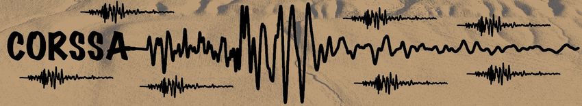
uncertainties for well constrained earthquake locations with a lower number of14 www.corssa.org observations since it is easier to fit a few observations than a large number of observations. This is, of course, contradicting the fact that earthquake locations are usually better constrained using a large number of observations. Furthermore, the scaling of the location uncertainties using the final data fit assumes that errors in the velocity model are normal distributed, which is not adequate and may even yield misleading results (Pavlis 1986). Formal uncertainty estimates computed for DD earthquake locations are usually a few orders of magnitude smaller than the corresponding uncertainties for single- event locations (e.g., Waldhauser and Ellsworth 2000). This is reflecting mainly the higher precision of relative arrival time measurements, in particular if cross- correlation methods are used to measure them. As for single-event locations, these lower uncertainties for relative locations do not provide information on the accuracy of the earthquake locations. For DD earthquake locations, these depend as well on the quality of the velocity model used for relocation. Furthermore, DD earthquake locations can be affected by variations in station distribution. These uncertainties cannot be quantified directly for DD earthquake location but can be quantified using statistical tests such as the jackknife method (Waldhauser and Ellsworth 2000). As direct-search methods sample the entire solution space they allow us to compute confidence regions that can be non-ellipsoidal in shape (e.g., Wilcock and Toomey 1991). Depending on the functions that are mapped these confidence regions may represent simple misfit surfaces (e.g., Billings et al. 1994b, Husen and Kissling 2001) or confidence regions, in the case of the posterior probability density function (e.g., Moser et al. 1992, Husen et al. 2003). Fig. 2 shows an example of a relatively well-constrained hypocenter location of a small earthquake recorded by the Swiss Digital Seismic Network. Another way of displaying the location pdf is by showing so-called density scatterplots (Lomax et al. 2000, Husen et al. 2003, Husen and Smith 2004). These density plots are obtained by drawing a subset of samples from the entire set of points sampled during the search, with the number of samples proportional the probability. Hence, a region with a higher probability to contain the earthquake location is shown by a higher number of samples (Fig. 2). From the set of pdf samples, traditional or Gaussian uncertainty estimates can be computed such as the expectation hypocenter location or the 68% confidence ellipsoid (Fig. 2). These estimates can be seen as the results from linearized earthquake location. The density scatterplots represent the geometrical properties of the location pdf, which represents most completely the result of probabilistic, direct, global-search methodologies. As can be inferred from Fig. 3, the shape of the location pdf can be quite complicated and irregular, and it is not adequately represented by traditional Gaussian uncertainty estimates. More examples of how the location pdf may look can be found, for example, in Lomax et al. (2008b).
Earthquake Location Accuracy                                       15

Fig. 2. Probabilistic location uncertainties of a relatively well-constrained earthquake location displayed as
a) confidence regions and b) density scatterplots. Maximum likelihood hypocenter locations are marked
with by stars; expectation hypocenter locations are marked by circles. Error ellipsoid corresponds to the
68% confidence ellipsoid as computed from the samples of the location pdf. Modified from Husen et al.
(2003).

It is important to note that only the probabilistic approach of Tarantola and
Valette (1982) and as implemented by Moser et al. (1992) and Lomax et al. (2000)
can separate the errors due to the velocity model and those due to the
measurement of arrival times. All other approaches, either linearized or based on
direct-search methods, describe the errors using a joint error distribution, such as a
generalized Gaussian (e.g., Billings et al. 1994a). Theoretically, the formulation of
Tarantola and Valette (1982) would allow a proper handling of the uncertainties
associated with velocity model errors and measurement errors. For reasons of
simplicity and to derive the location pdf analytically the a priori density functions
describing the state of knowledge of the velocity model and measurement errors
had to be assumed to be Gaussian. However, Pavlis (1986) found that it may not
be adequate to represent the velocity model error as a Gaussian distribution with
zero mean and that, under this assumption, misleading results can be obtained.
Therefore all location methods suffer from an inappropriate handling of velocity
model errors, which will be discussed in more detail in section 3.2.
16                                                 www.corssa.org

Fig. 3. Density scatterplots of two poorly-constrained earthquake locations recorded by the Swiss Digital
Seismic Network. Maximum likelihood hypocenter locations are marked by the intersection of dashed lines.
Black circles mark expectation hypocenter locations. Error ellipsoid corresponds to the 68% confidence
ellipsoid as computed from the samples of the location pdf. Black triangles denote station locations. Note
that for these location pdf the error ellipsoid does not present an adequate representation of the location
uncertainties. Modified from Husen et al. (2003).

Uncertainty estimates based on network criteria
As outlined above, all earthquake location methods provide uncertainty estimates
under certain assumptions. Nevertheless, many earthquake catalogs either do not
provide this information or, if provided, the information is based on linearized
location methods with rather unreliable uncertainty estimates. Earthquake location
studies based on direct-search methods are still a minority. Because of that people
have tried to assess the reliability of earthquake locations using so-called network
criteria. These criteria usually include the following measures, which can be derived
from the geometry of the stations that recorded the earthquake or from the data
fit:
     1.   nobs = number of observations (P- and S-wave arrival times);
     2.   GAP = greatest azimuthal angle without observation;
     3.   DIST = distance to the closest station;
     4.   RMS = root mean square of the travel time residuals for the final
          earthquake location.

Using these criteria several studies tried to establish “rules of thumb” that would
describe well-constrained hypocenter locations (see for example Gomberg et al.
Earthquake Location Accuracy 17
1990, Bondar et al. 2004 and references therein). Some of these well-known rules
are:
1. You need a GAP < 180°for a well constrained earthquake location (Kissling
1988);
2. You need at least eight travel time arrivals, of which at least one is an S-
wave arrival, and at least one was reported from a station within a focal
depth’s distance from the epicenter for a well constrained hypocenter
location (Chatelain et al. 1980);
3. A correctly timed S-wave arrival recorded within 1.4 focal depth’s distance
from the epicenter provides a unique constraint on focal depth (Gomberg et
al. 1990).
These rules of thumb try to mimic the fact that for a stable earthquake location,
matrix A in equation (2) needs to have a low condition number, i.e. the columns of
matrix A need to be linearly independent (see Lee and Stewart 1981, page 137).
The elements of matrix A are the spatial derivatives of the travel times from the
trial hypocenter to the stations. These depend on the seismic velocity and the take-
off angles of the seismic rays at the hypocenter. As the take-off angles depend on
the geometry of the hypocenter with respect to the stations, the geometry of the
observing stations plays a critical role in how well constrained an earthquake
location is. To minimize the condition number of matrix A columns need to be
linearly independent. This can be achieved, for example, by ensuring a wide range
of take-off angles, which is most likely achieved by using a large number of arrival
time observations at different distances. The requirement of one arrival from a
station within a focal depth’s distance ensures that there is at least one up-going
ray.
Focal depth is generally less well constrained than epicenter. This can be
understood by considering the properties of matrix A. Since the first column of
matrix A contains the partial derivatives with respect to the origin time, which are
always one, the chances that the fourth column, which contains the partial
derivatives with respect to focal depth, becomes a multiple of the first column is
high. This can happen in a situation where all stations are located at a similar
distance to the epicenter or if the P-wave arrivals are coming from the same
refractor in a layered model. Similarly, the well-known tradeoff between origin time
and focal depth can be explained by this linear dependence between the first and
fourth column of matrix A. Fixing focal depth, as done by many linearized location
methods, will remove this tradeoff and lower the condition number of matrix A,
thus yielding a more stable inversion. The use of depth phases (pP, pwP, sP) will
greatly improve focal depth estimates as their partial derivatives differ significantly
in magnitude from those of the direct P-arrival (Engdahl 2006). Furthermore, the
tradeoff between origin time and focal depth is avoided as the partial derivates of
depth phases are opposite in sign to the direct P-arrival.
It is important to note that the rules of thumb discussed above only refer to the
precision of an earthquake location. They usually do not give estimates on the
accuracy of an earthquake location. To assess the accuracy of an earthquake
location, sources with known locations, such as explosions or mine blasts, need to18 www.corssa.org be used. For example, Bondar et al. (2004) used data from exceptionally well- located earthquakes and nuclear explosions to establish epicenter accuracy based on seismic network criteria for different scales (local, regional, teleseismic). Their results indicate that rather strict criteria are needed to obtain high-quality earthquake locations: e.g., for local network locations 10 or more stations, a GAP < 110°, DIST < 30 km, and a secondary azimuthal gap < 160° are needed to obtain a location accuracy of 5 km with a 95% confidence level. The study of Bondar et al. (2004) does not give similar estimates for focal depth. Hence, it would be best for a given catalog to estimate these parameters using the approach of Bondar et al. (2004) but including focal depth as well. The effect of adding S-wave arrivals to location uncertainties S-wave arrivals provide an important constraint on focal depth of an earthquake, in particular if they are observed at a station within 1.4 focal depth’s distance (Gomberg et al. 1990). Within this distance the partial derivative of an S-wave arrival with respect to focal depth provides a unique constraint due to the lower seismic velocities of the S-waves. An S-wave arrival does not only provide an important constraint on focal depth but also on location uncertainties. As can be seen in Fig. 4 the use of S-wave arrivals dramatically reduces the uncertainty in focal depth; without S-wave observations, the focal depth of the earthquake is nearly unconstrained despite the fact of a relatively small GAP (GAP=144°) and a station within focal depth distance (DIST=23.7 km). Focal depth is unconstrained for this earthquake because the range of station distances is relatively poor and, consequently, all the rays show similar take-off angles (Fig. 4). The situation is greatly improved by adding S-wave arrivals due to the lower seismic velocities of the S-waves. Compared to the location uncertainties the corresponding shift in epicenter and focal depth is relatively small indicating that the main effect of adding S-wave arrivals for this earthquake was a decrease in the location uncertainties. It is important to note, that adding S-wave arrivals does not necessarily improve the location accuracy. First, picking of S-wave arrivals is complicated by converted phases which can arrive shortly before the actual onset of the S-wave. Such a phase misidentification can yield a systematic bias in the earthquake location which cannot even be detected due to the apparent decrease in the formal uncertainties (Gomberg et al. 1990). Second, the assumption of using a constant P- to S-wave velocity ratio to locate an earthquake in the absence of an S- wave velocity model can also lead to a location bias (Maurer and Kradolfer 1996). In both cases, an earthquake location obtained using P-wave arrivals only will provide an improved location accuracy without a potential bias; however, using only P-waves also yields a lower precision. Fig. 4 is also a nice example on how unreliable the earthquake’s RMS value is to assess location quality. Although RMS is a factor of three lower, the location obtained using P-wave arrivals only is not better; it is actually worse. For a given velocity model and a set of arrival times, RMS is primarily a function of observations: The fewer observations used to locate the earthquake, the lower the RMS is. This resembles the fact that it is easier to fit a small set of observations than a large set of observations. RMS can be used as a measure for location quality but only if the “noise level” of the travel time residuals for a given velocity model
Earthquake Location Accuracy                                     19

has been estimated. This noise level is a function of the measurement errors and
amount of true Earth structure that is not accounted for in the velocity model. One
way of assessing the noise level is by computing a so-called minimum 1-D model,
which will give a final RMS value of travel time residuals reflecting the noise level
contained in the data and in the velocity model (e.g., Kissling 1988, Husen et al.
2003).

Fig. 4. Earthquake location for an intermediate depth earthquake in the subduction zone in Alaska.
Density scatterplots are shown for the location using only P-wave arrivals (grey) and using P- and S-wave
arrivals (black). Map in the lower right shows epicenter location (circles) and geometry of stations (black
triangles) used to locate the earthquake. The earthquake was located using the NonLinLoc software
(Lomax et al. 2000) and one dimensional velocity models for P- and S-wave velocities (van Stiphout et al.
2009). Note the significant decrease in the formal uncertainties (as represented by the density scatter
plots) when S-wave arrivals are used to locate the earthquake. See text for discussion on the effect of S-
wave arrivals on earthquake location.

3.2 Accuracy and sources of systematic bias in earthquake locations
20                                       www.corssa.org

The location uncertainties discussed in the previous section are caused by
measurements errors and by the unfavorable geometry of stations that recorded the
earthquake. The combination of both factors leads to scatter in the earthquake
locations that may be quite complicated in shape (e.g., non-ellipsoidal shape). If the
measurement errors are known a priori, these location uncertainties can be
adequately computed using modern location techniques, such as probabilistic
direct-search methods. Uncertainties in earthquake locations can also be introduced
due to errors in station parameters (location, timing), due to misidentification of
seismic phases, and due to errors in the velocity model used to compute the
earthquake locations. In general, these errors lead to a systematic bias in
earthquake locations and, hence, they affect the accuracy of an earthquake location
(e.g., Jordan and Sverdrup 1981, Pavlis 1986). Moreover, they are difficult to
detect and do not follow standard statistical distributions, which makes it difficult
to properly account for them in earthquake location. In this section we will discuss
two of the most commonly known sources of systematic bias in earthquake
location–phase misidentification and velocity model errors–and demonstrate how
they can affect earthquake location.
Misidentification of seismic phases
Earthquake location relies heavily on correct phase identification since it tries to
minimize residuals between observed and calculated travel times. As such, observed
and calculated travel times must correspond to the same phase. Common practice
in arrival time data analysis is to assign a certain phase label (P, Pn, S, Sn, etc.),
which is then used by the location program to compute the corresponding travel
time. Assuming a good signal-to-noise ratio, phase identification is generally easy
for the first arriving, direct P-wave (often called Pg) within the first 60 km of an
earthquake location. It becomes complicated, however, at the cross-over distance,
where the Pg phase and the upper mantle Pn phase arrive close in time. Beyond
the cross-over distance, the amplitude of the Pn phase is small compared to the
later arriving Pg phase or to the reflection from the Moho (PmP phase) and, hence,
can be missed in the noise (e.g., Diehl et al. 2009b). As a consequence, the
secondary Pg or PmP phase is picked but labeled and used in the location
earthquake as a first arriving P-wave. Similarly, the identification of depth phases
is difficult for shallow events due to the short time delay relative to the first
arriving P-wave (e.g., Myers et al. 2009). The correct identification of S-waves is
hampered by converted phases which may arrive shortly before the actual S-wave.
Therefore, S-wave arrivals should only be picked using all three components,
preferably rotated (e.g., Diehl et al. 2009a).
Without waveforms, the detection of misidentified phases is difficult. For local and
regional distances, arrival times can be plotted in reduced record sections similar to
record sections used in refraction seismology. In such plots theoretical arrival times
for main crustal phases (Pg and Pn) can be compared with the observed arrival
times and gross inconsistencies can be detected (e.g., Diehl et al. 2009b). For
example, a secondary arriving Pg or PmP phase which was picked as a first-
arriving P phase can be easily be detected beyond the cross-over distance because
the phase locates closer to the arrival time branch of the Pg or PmP phase than to
the first arriving Pn phase. The usefulness of such an approach for large data sets
Earthquake Location Accuracy                          21

is limited since it is laborious to perform this kind of analysis for each earthquake.
At the same time, record sections can become quite complicated for regions with
significant Moho topography. The differences between theoretical travel times for
seismic phases is usually larger than the measurement error of the arrival time
picking. Therefore, the arrival time of a phase is an important constraint in phase
identification. This can be used to identify phase names by comparing observed
arrival times with theoretical arrivals for all phases under consideration. Of course,
the success of such an approach depends critically on the quality of the earthquake
location and on the quality of the velocity model. One way of accounting for these
problems is to invert a high-quality set of arrival times simultaneously for a so-
called minimum 1-D model that includes earthquake locations, 1-D seismic
velocities and station delays (Kissling 1988). Such a model allows us to detect
systematic errors in arrival time data by analyzing station delays and travel time
residuals (Maurer et al. 2010). Another approach used for global data sets is based
on travel time probability density functions for a number of phases, including
depth phases. Engdahl et al. (1998) used these probability density functions to
randomly select a phase label according to the probability calculated for each
potential phase type. Myers et al. (2009) took this approach even further to
include phase identification in their Bayesian hierarchical multiple-event seismic
location method (Myers et al. 2007). This approach mitigates the confounding
effects of earthquake location errors and travel time prediction errors in a full
probabilistic framework.
On a global scale, the use of probabilistic phase identification yields significantly
improved focal depths estimates. This was partly attributed to the use of depth
phases (pP, pwP, sP, and PcP) that could be more reliably identified using
probabilistic phase identifications (Engdahl et al. 1998). On a local and regional
scale, the presence of misidentified phases can severely bias earthquake locations.
For example, differences in epicenter locations of up to a 30 km were detected in
the Alpine region by comparing locations based on routine picks and on revised
picks (Diehl et al. 2009b). The differences were attributed to the presence of
secondary Pg phases that were picked and identified as first-arriving P phases.
Similarly, the effect of a single station with wrong coordinates, which in terms of
error magnitude can be equivalent to a misidentified phase, can yield location bias
of several kilometers (Maurer et al. 2010). Whereas the bias in epicenter shows a
linear behavior, the bias in focal depth is clearly nonlinear, i.e., no gradual shift is
observed in focal depth with increasing distance between true and wrong station
coordinates. Fig. 5 shows an example of a Ml=3.4 earthquake recorded at the Swiss
Digital Seismic Network that was shifted by 4 km to more shallow depth because of
a secondary Pg phases that was picked and identified as first-arriving Pn phase at a
single station. The effect is likely so pronounced in the example because phase
misidentification occurred at a station that provided an important constraint on
focal depth due to the arrival of a Pn phase at this distance. It is also important to
note that formal uncertainties as computed by the location pdf do not differ
between the two locations. This demonstrates that this kind of error is not reflected
in the computation of the formal uncertainties.
The issue of phase identification is less critical for relative location techniques if
cross-correlation methods are used to measure delay times. These delay times can
You can also read