Effect of Joule Heating on Cell Viability and Device Reliability
←
→
Page content transcription
If your browser does not render page correctly, please read the page content below
Preprints (www.preprints.org) | NOT PEER-REVIEWED | Posted: 25 May 2021 doi:10.20944/preprints202105.0591.v1

 Article

 Effect of Joule Heating on Cell Viability and Device Reliability
 Caffiyar Mohammed Yousuffa,*, Vineet Tirthb,c, Mohamed Zackria Ansar B.Ia, Kashif Irshadd*, Ali Algahtanib,c,
 Saiful Islame

 a C. Abdul Hakeem College of Engineering and Technology, Melvisharam, India.
 (CMY)(MZA)(cmd.yousuf@gmail.com, zackriaansarbi@gmail.com)
 b Mechanical Engineering Department, College of Engineering, King Khalid University, Abha-61411, Asir,

 Kingdom of Saudi Arabia (VT, AA) vtirth@kku.edu.sa, alialgahtani@kku.edu.sa
 c Research Center for Advanced Materials Science (RCAMS), PO Box 9004, Abha-61413, Asir, Kingdom of

 Saudi Arabia (VT, AA)
 d Center of Research Excellence in Renewable Energy (CoRE-RE), King Fahd University of Petroleum & Min-

 erals, Dhahran, 31261, Kingdom of Saudi Arabia (KI)
 e Civil Engineering Department, College of Engineering, King Khalid University, Abha-61411, Asir, Kingdom
 of Saudi Arabia (SI) sfakrul@kku.edu.sa
 * Correspondence: kashif.irshad@kfupm.edu.sa (KI); Tel: +966 54 785 4711
 cmd.yousuf@gmail.com (CMY); Tel: +91 63693 43657

 Abstract: The application of electrode-based microfluidic devices in biological entity often imposes
 a problem due to joule heating. The strong applied potentials or micro channels having narrow
 cross sections generate undesirable temperature inside the microfluidic channels leading to strong
 thermal distribution inside the micro channel. When intrinsic distribution of temperature, if not fix
 with threshold value, causes device damage or cell loss. In this work, we investigate the effects of
 temperature generated due to joules heating effects and we attempt to address the design con-
 straints for minimizing the joule heating effects in the microfluidic device for developing effective
 microfluidic device. The device reliability was analyzed under different parametric constraints for
 various types of substrate materials (PDMS, PMMA, Polyimide and glass). We also attempt to in-
 vestigate the effects of cell reliability due to strong temperature gradients generated through dif-
 ferent applied potentials on different cell types. Furthermore, the response of the device perfor-
 mance due to different electrode configuration and different conductivity of the medium was also
 studied. Our investigation will eventually provide guidelines for microfluidic researchers to fab-
 ricate efficient electrode based microfluidic device which will ultimately help to choose a critical
 channel dimensions, threshold potentials, and conductivity of solutions in order to avoid device
 damage and cell loss.

 Keywords: cell viability; device reliability; joule heating; eDEP devices.

 1. Introduction
 When cell sorting is carried out inside the microchannel, often forces is needed to
 drive the sample flow throughout the microchannel. Electrokinetic phenomenon arises
 due to the interaction occurring between induced electric charges and external electric
 field. There exists many electrokinetic methods to control the flow of the sample inside
 the micro channel, but dielectrophoresis remains superior [1]. Joule heating is often ob-
 served in devices which uses electrode to drive the fluid flow. Joule heating arises due to
 current flow through the buffer solution [2]. This current arises from the applied electric
 potential on the electrodes inside the microchannel. The interaction of current with the
 buffer solution has a keen impact on electrical resistance. When an electrical resistance
 increases, more heat is dissipated onto the fluid. These results in temperature gradient
 formation in the fluid present inside the microchannel. The strong electric field gradient
 generated using Electrode based microfluidic devices has been widely used in
 bio-medical application for cell trapping[3], for studying cell characteristics [4] and cell

 © 2021 by the author(s). Distributed under a Creative Commons CC BY license.
Preprints (www.preprints.org) | NOT PEER-REVIEWED | Posted: 25 May 2021 doi:10.20944/preprints202105.0591.v1

 2 of 20

 sorting [5]. Behavior of neurons were recorded using an integrated electrode array [6].
 Cells like melanoma cells (M2), K562 cells was cultured and tested for viability, cell
 shipment at different temperature conditions [7]. Shouhui et al. demonstrated that pros-
 tate-specific-antigen (PSA) in human serum can be detected using the screen printed
 electrode [8]. Chen et al. demonstrated that Micro electrodes can effectively be used for
 separating the polystyrene particles [9].
 Joule heating generated inside the microchannel also find application in many ways
 such as trapping and concentration of cells[10].The joule heating in polymers changes its
 microstructure and this improves the electrical properties of composite [11].The bio-
 compatible temperature on electromagnetic based microfluidic device is achieved due to
 the internal temperature generated due to joule heating [12]. Even though the joule
 heating has many application as mentioned in above literature, the impact on human
 cells due to joule heating often leads to lethal injury or cell death [13]. Joule heating in an
 electro-osmotic flow based microfluidic devices results in deviation of velocity inside the
 microchannel [14] which results in cell separation failure. The application in which strong
 electric field density generated inside a microchannel results in higher joule heating effect
 which denatures the protein components inside the human cells [15]. Furthermore, the
 effect of joule heating also causes inefficient device performance in application towards
 cell sorting (lowers separations resolution) [15]. Several DEP based microfluidic devices
 were studied and experimentally investigated for cell sorting efficiency. It has been in-
 vestigated that, a typical electrode configuration can generate a strong DEP force at
 minimal applied voltages for efficient cell separation [16–18]. However, improper design
 of electrode geometry may also results in strong joule heating effects that eventually de-
 stroys the device performance.
 In our recent work, we studied the sorting efficiency of red blood cells, white blood
 cells, platelets, antigen presenting cells and circulating tumor cells using different elec-
 trode geometries using DEP phenomena and optimal device design configuration was
 found with triangular electrode. This DEP based cell sorting enables to separate distinct
 cell types in different collection outlets in a single run which can be further used for
 DNA extraction, drug discovery, high-throughput molecular screening, understanding
 prognostic information about patients [19]. The electrode geometry has a direct influence
 in the electric field distribution inside the microchannel [20]. The amount of heat dissi-
 pated in the fluid also relies on electrode[21]. The electrode width and electrode height
 remains responsible in generating the amount of dep force over the human cells.
 Certain electrode geometry requires high applied electrode potential for cell sorting.
 However, an application of high electric field creates strong thermal gradient across the
 micro channel, especially around the electrode tip, creating strong joule heating region.
 The cells that exposes in these region will eventually get impacted by high temperature
 causing cell damages if the threshold temperature exceeds 316.25K [22]. The type of
 electrode and substrate materials also contributes for generating different field gradient
 for the applied voltage. In case of DEP based cell sorting application, threshold applied
 potential is required for effective separation [23–25], however for few electrode materials
 used in device, the device may generate strong temperature gradient that affects the cell
 viability when it is flown out at collection outlet [26,27], though separation may be effec-
 tive [28]. This ultimately shows the device degradability for cell sorting application
 [29,30].
 Numerous attempt has been made to understand the effects of joule heating with
 respect to cell death and device reliability. Erickson et al. performed combined experi-
 mental and numerical analysis of the joule heating and heat transfers at microchannel
 intersection in polydimethylsiloxane (PDMS) and hybrid PDMS/Glass microfluidic sys-
 tems [31] and demonstrated that hybrid microfluidic system helps in maintaining the
 uniform and low buffer temperature. Chein et al. presented analytical model for predic-
 tion of pressure and temperature under joule heating effect in microfluidic device [32]. In
 their study, they observe that, fluid temperature variation is with respect to heat transfer
Preprints (www.preprints.org) | NOT PEER-REVIEWED | Posted: 25 May 2021 doi:10.20944/preprints202105.0591.v1

 3 of 20

 coefficient of cooling mechanisms. Zhu et al. studied the distribution of temperature on
 the surface of polymeric chip by using advanced thermograph system [34]. They re-
 ported that joule heating produced at high electric field can rise temperature of device
 above 40°C additionally. It is further observed that, joule heating also affect the flow
 profile in dielectrophoretic microfilters [33]. Brans et.al. observed the effects of temper-
 ature profile on liquid inside a microchannel in which the particle is suspended [35].
 The particles are optically trapped to establish the temperature of the surrounding liquid
 and temperature increase due to Joule heating of the ionic liquid was monitored using
 their setup. They compared Brownian movement of particles at both room temperature
 and motion of microparticles when the power remains dissipated inside the microfluidic
 system and provided the estimate of temperature increase inside the microchannel. In
 application towards cell sorting and isolation, the collection of healthy cell after the cell
 sorting mechanism tends to offer a wide range of scope in the field of DNA extraction,
 drug discovery and cell culture. Most of the reported literature shows that, the system
 either requires high voltage for cell separation resulting in joule heating effect or com-
 plicated design constraints [3,36,37]. Application of higher voltages on the microfluidic
 device also damages the microchannel hindering its application for multiple runs.
 All the above literature has highlighted the investigation on the joule heating on the
 device or the factors which contributes joule heating effects. In order to develop an effi-
 cient and reliable microfluidic device to avoid cell damages in the presence of joule
 heating needs to be critically addressed in all electrode-based DEP devices. Rise in device
 temperature is often observed in all electrode based DEP system resulting in cell death,
 separation failure which makes the device non-reliable for downstream analysis. All
 eDEP based devices produces joule heating resulting in increased temperature gradient
 inside a microchannel when design constraints not considered properly. Therefore, the
 device experiences larger unusual temperature leaving the cells damaged.
 All these issues can be overcome by selecting proper electrode geometry, electrode
 potentials and choosing proper substrate materials which will eventually causes low
 thermal effects inside the devices and avoids the issues of cell damage/loss and provides
 reliable device performance. It is further noted that, the conductivity of the medium also
 has significant impact on joule heating inside a microchannel when the applied voltage
 exceeds above the threshold value [38]. Therefore, in this research, we attempt to explore
 the effect of various parameters including applied potential, electrode geometry, sub-
 strate materials and conductivity of the medium which can provide optimal solution to
 avoid joule heating effects thereby improving device performance, reliability and
 avoiding cell loss.
 We observed the effects of temperature on the cell when it is exposed to the region of
 strong thermal gradient at various positions in a microchannel (initial, center and rear
 end). The thermal impact on cells and its survival time gives us a clear idea about cell
 viability. Our study reveals the maximum temperature a cell can withstand inside a mi-
 cro channel to remain viable and maximum voltages that can be applied to the device for
 effective DEP based cell separation under various parametric constraints. We attempt to
 evaluate the device performance by tweaking around various geometrical parameters
 including electrode geometry, substrate materials, applied potentials and medium con-
 ductivity. An effective and optimum design solution is derived from our study that will
 enable the future researchers to design and develop reliable DEP devices and other elec-
 trode based microfluidic devices for various bio clinical applications.

 2. Materials and Methods

 2.1.Theory of DEP and Joule heating
 The Movement of uncharged particle under the region of non-uniform electric field
 constitutes a force termed as ‘Dielectrophoresis’. Under this condition, each particle will
 have different coulombic force at both ends which give rise to electrokinetic flow
Preprints (www.preprints.org) | NOT PEER-REVIEWED | Posted: 25 May 2021 doi:10.20944/preprints202105.0591.v1

 4 of 20

 movement due to net force imbalance. The DEP force of the spherical particles is ex-
 pressed as [39] ,

 FDEP(i) = 2 ε0εmRe[fCM (ω)] R3 ∇E2 (1)

 Where ‘εm’ is the relative permittivity of the suspending medium, R is the radius of
 the particle, ∇E2 denotes gradient of the electric field, Re[fCM (ω) denotes the real part of
 the Claussius Mosotti [CM] factor that determines effective polarisability and is ex-
 pressed as[40] ,

 ͂ − ͂
 ͂ , ͂ = (2)
 ͂ + 2 ͂

 Where ε ̃ is the complex permittivity and defined as,

 ͂ = − (3)

 Therefore, CM factor can be written as,

 − + / ( − )
 , , , , = (4)
 + 2 + / ( + 2 )

 The CM factor is dependent on the complex permittivities of the particles and the
 suspending medium. When the suspending medium is less polarizable than the particles
 are attracted to the higher field region commonly referred as positive dielectrophoresis
 (pDEP), in contrast, when the suspending medium is more polarizable consequently the
 particles are repelled from the region of higher electric field, this give rise to negative di-
 electrophoresis (nDEP).

 If ‘σ’ is the conductivity of the buffer solution between the positive and negative
 electrode then the heating power per volume V depends linearly to conductivity of the
 suspending medium (σ) and to the square of the electric field strength and is expressed as
 [41] ,

 = = . ∝ . (5)

 Where ‘rms’ denotes root mean square value, ‘U’ represents the voltage applied
 between the electrodes. The amount of heat generated (Pheat) is equal to the amount of
 heat dissipated under the steady state condition [2]. The Electric field (E rms) depends on
 the conductivity of the suspending medium (σ) which is greatly affected by the change in
 temperature and is expressed as ,

 σ = σ0[1 + α(T − T0)] (6)

 Here, ‘σ0’ refers to the conductivity at a reference temperature T0, and α is the tem-
 perature coefficient of the suspending medium. The Joule heating-induced temperature
 field is governed by the energy equation expressed as [42] ,

 ρ∁ + u ⃗ ∇ = ∇ + λ( )(∇ϕ) (7)
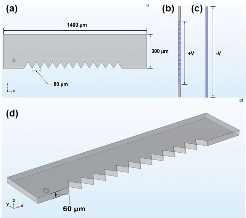
Preprints (www.preprints.org) | NOT PEER-REVIEWED | Posted: 25 May 2021 doi:10.20944/preprints202105.0591.v1

 5 of 20

 where ∁p and kl represents the specific heat and thermal conductivity of the buffer
 solution, respectively, and they are considered to be constant (i.e., independent of tem-
 perature).

 2.2.Geometry of the Microfluidic chip
 The three dimensional microfluidic chip is shown in Figure (1). Device consists of
 cells mimicking human WBC, APCs and CTCs in the size range of 15 µm [43]. Under the
 application of DEP force each cells experiences different dep forces [18]. Electric potential
 is applied on top and bottom of device for generating non-uniform electric field. +V is
 applied on the bottom of the device illustrated in Figure 1(b) and -V is applied on the top
 of the device as shown in Figure 1(c). The device has a channel length of 1400 µm and
 channel width of 300 µm. The electrolyte used is PBS solution in the ratio of 1:9 to the
 blood was used throughout the simulation. The device has a thickness of 60 µm as seen in
 Figure (1d).

 Figure 1. (a) Three dimensional microfluidic device design represented in XY axis orientation. (b)
 Bottom view of triangular electrode +V applied. (c) Top view of the electrode with -V electrode. (d)
 An intermediate view representing thickness of the microfluidic device.

 2.3.Numerical Analysis :
 By using COMSOL Multiphysics software (COMSOL v5.3a), a three dimensional
 simulation model was created in order to characterize the cell viability and device relia-
 bility. Three dimensional model was developed as 2D model failed to show the distribu-
 tion of temperature in the thickness of the microfluidic chip and around the surface of the
 cells. Electric field profile is simulated using electric current model. Temperature distri-
 bution on the cells caused due to joules heating effect is simulated using bio-heat transfer
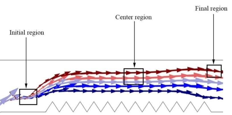
Preprints (www.preprints.org) | NOT PEER-REVIEWED | Posted: 25 May 2021 doi:10.20944/preprints202105.0591.v1

 6 of 20

 model is used. These interfaces were used sequentially to model the problem numerically
 and detailed description on these interfaces are listed below.
 (i) Electric current interface is used in simulation in order to generate non-uniform
 electric field within the microchannel. The applied electric potentials are regulated by
 Laplace’s equation, given by E= ∇φ. The electrodes are arranged adjacently to the chan-
 nels wall and are provided with the applied voltages +V and -V on the top of the mi-
 crochannel. The rest of the domain inside the model are insulated.
 (ii) Bio-heat transfer interface in simulation is used to generate the thermal distribu-
 tion on the blood cells which submerged with the Phosphate buffer solution for effective
 isolation. In order to solve energy equation the outer boundaries were set to room tem-
 perature of 290 K. The interface provides joules heating effect (i.e., the thermal exposure
 over the cell caused due to heat dissipated on the solution). The heat transfer equation (7)
 governs the different temperature distribution inside the microchannel.
 (iii) The geometry is meshed with free tetrahedral with minimum size element of
 0.18 µm and maximum size element of 50 µm and for the discretization of 62238 mesh
 elements. A time dependent solver is used to solve electric field and thermal distribution
 resulted through joules heating simultaneously. The three dimensional geometry and its
 electrode is defined under the graphic section window.

 3. Results
 The cells are subjected to different region where it experiences different amount of
 dep force. The cell path from the initial separation to the final collection outlet has been
 listed in Figure (2). The three various region of measurement of thermal effects on the
 cells include initial region (near by the inlets) at a channel length of 100 µm and channel
 width of 30 µm. The next is the centre region (between the electrodes) at a channel length
 of 700 µm and channel width of 200 µm. The final region is nearer to outlets at channel
 length of 1300 µm and channel width of 240 µm . Each of the cells have distinct cell size.
 However, all these cells will receive equal amount of thermal effects since they are kept
 consistent in all the three region. Consequently, a single cell is used for the complete
 simulation. The region of measurement provides valuable insight about whether the cells
 remains healthy or exposed to unusual temperature which results in cell destruction or
 cell dead. Amount of temperature exposed on the cells due to buffer conductivity , elec-
 trode shape, substrate material, various metal electrodes was analysed and discussed in
 below subsections.

 Figure 2. Shows the measurement region inside the microchannel on the particle tracks towards the
 outlet

 3.1. Effect of Buffer Conductivity:
 The effect of buffer conductivity on various Cells were analysed. The different cell
 types exerts same amount of temperature throughout the simulation while the
 threshold temperature for individual cell types differs accordingly. For the human cells
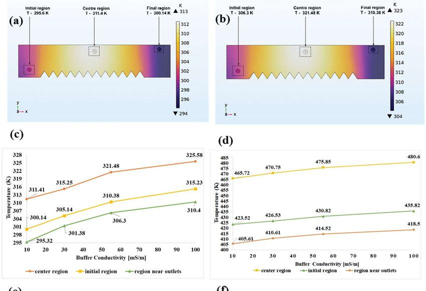
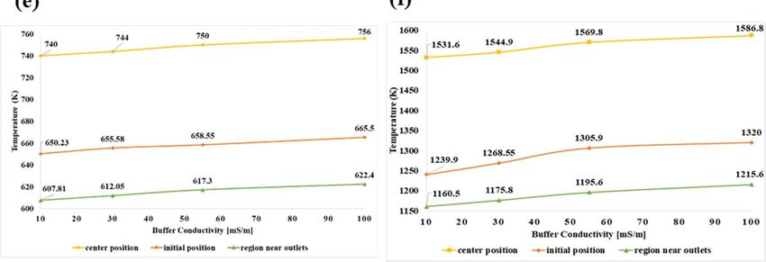
Preprints (www.preprints.org) | NOT PEER-REVIEWED | Posted: 25 May 2021 doi:10.20944/preprints202105.0591.v1

 7 of 20

 the damage occurs at 316.5 K [22]. The amount of cell damage is proportional to time it is
 exposed[44]. Buffer conductivity ranging from 10[mS/m] to 100 [mS/m] was used in or-
 der to evaluate the amount of temperature exerted on the cells. The region is classified as
 initial position, centre position (region with high electric field density) and final region
 (near to outlets).This region also refer to the tracks which it follow to reach their corre-
 sponding collection bins[18]. When the cells are at the initial position as seen in Figure
 3(a) with a buffer conductivity of 10[mS/m] the temperature exerted over the cells is
 found to be 300.14 K at an applied electrode potential of 5Vpp. Under the same applied
 voltage, when a buffer conductivity is increased to 30 [mS/m] for the same position of the
 cell, the temperature exerted over the cell is found to be 305.14K as shown in Figure 3(b).
 With further increase in buffer conductivity of 55 [mS/m] the temperature exerted over
 the cells get raised to 310.38K .Further increase in buffer conductivity to 100 [mS/m], the
 temperature of 326.23K is generated over the cells as shown in Figure 3(c). The cells were
 tested at 10V with different buffer conductivity as shown in Figure 3(d), buffer conduc-
 tivity from the range (10-100mS/m) was tested at 15V as shown in Figure 3(e). Maintain-
 ing 25V with different buffer conductivity is shown in Figure 3(f). All these plot demon-
 strates that temperature increases with the increase in buffer conductivity at a constant
 applied potential. The temperature above 316.5K on the cells will often lead to cell
 damage leading to the cell death if they are analysed over a long period of time as stated
 in [45–47]. The second phase of simulation deals with same range of buffer conductivity
 from (10 - 100 [mS/m]) at the channel length of 700 µm and channel width of 200 µm.
 As these region is nearer to the electrode, the distribution of non-uniform electric field is
 greater compared to that of the other region. Nevertheless, the cells passing through
 these region is intended to have more thermal effects. This condition exhibits larger
 thermal values as the applied potential directly influence the buffer solution since it is
 nearer to the electrode. The temperature exerted by the cell is found to be gradually in-
 creasing from 311.41K to 325.58K with an increase in buffer conductivity. The buffer
 conductivity of 10 [mS/m] and 30 [mS/m] is considered to be safer with a least cellular
 damage. While increasing buffer conductivity from these range causes irreversible cel-
 lular damage leading to cell death as it exceeds the threshold temperature of the cells.
 The final phase of the simulation was carried out for the same range of buffer conductiv-
 ity nearer to the collection outlet bins. The cell was positioned at the channel length of
 1300 µm and channel width of 220 µm. The cells making their way from previous region
 enters these region later on collected at the outlet as indicated in [18,48]. Thermal effects
 tend to be low at this region of the device ranging from 295.32K to 311.41K as shown in
 Figure 3(a). The healthy cells entering this region never suffer any lethal injury or cell
 death throughout the buffer conductivity ranging from 10 to 100 [mS/m]. This detailed
 result provides guidelines on cell viability.
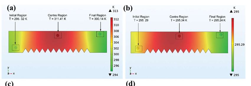
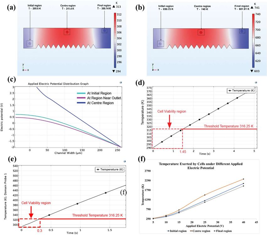
Preprints (www.preprints.org) | NOT PEER-REVIEWED | Posted: 25 May 2021 doi:10.20944/preprints202105.0591.v1

 8 of 20

 Figure 3. (a) Temperature exerted by cells in all three region with buffer conductivity 10 mS/m. (b)
 Temperature exerted by cells in all three region with buffer conductivity 55 mS/m. (c) Response of
 different buffer conductivity at three region with a constant applied potential of 5V. (d) Response
 of different buffer conductivity at three region with a constant applied potential of 10V. (e) Re-
 sponse of different buffer conductivity at three region with a constant applied potential of 15V. (f)
 Response of different buffer conductivity at three region with a constant applied potential of 25V.

 3.2.Effects of Applied Electric Potential
 The Applied electrode potential was studied for the device reliability and cell relia-
 bility. The heat energy generated due to joule heating is directly proportional to the
 square of the electric field applied [49]. The applied potential in simulation are 5V , 10V,
 15V, 25V, 40V. Under applied potential of 5V, the cells were found to be healthy and vi-
 able as the threshold temperature does not exceeds more than 316.25 K as shown in Fig-
 ure 4(a). The electric field at the three region is different, as a result thermal distribution
 in each of these region is unique. When the applied potential is increased to 10V, the cells
 exerts temperature more than 400 K . With the further increase in voltage to 15V, the cells
 exerts temperature more than 600 K as shown in Figure 4 (b). Complete cell separation
 can be easily achieved at the time period of 0.5 to 1 second [50]. Distribution of applied
 electric potential inside the channel of 300 µm is shown in Figure 4(c). The time at which
 the cell reaches it threshold temperature level is found to be 1.45 seconds when 5V ap-
Preprints (www.preprints.org) | NOT PEER-REVIEWED | Posted: 25 May 2021 doi:10.20944/preprints202105.0591.v1

 9 of 20

 plied as shown in Figure 4(d). Hence the cells remain viable for long time in this case.
 Further increase in applied potential to 10V time gets reduced to 0.3 seconds as shown in
 Figure 4(e). Inference with respect to threshold temperature is listed in Table 1.

 Table 1. Time required to reach threshold temperature at different electric potential .

 Time to reach
 Applied Electrode threshold Temperture
 Inference
 Potential 316.25 K
 (in seconds)
 Effective cell separation with maximum
 5 1.45
 cell viability
 10 0.3 Cell Separation leading to cell death
 15 0.15 Cell Separation leading to cell death
 25 0.04 Cell Separation leading to cell death
 40
Preprints (www.preprints.org) | NOT PEER-REVIEWED | Posted: 25 May 2021 doi:10.20944/preprints202105.0591.v1

 10 of 20

 Figure 3. (a) Temperature distribution in different region at 5V. (b) Temperature distribution in
 different region at 15V. (c) Potential distribution at three regions at 5V (d) Threshold temperature
 plot for 5V. (e) Threshold temperature plot for 10V. (f) Temperature exerted by cell at different
 applied electric potential.
 The impact of applied electric potential on cell viability was analysed in all the three
 regions. The initial region (near to inlet) receives less temperature than the centre region.
 The thermal distribution on the cells at different applied electric potential in initial region
 is listed in table (1). We varied the applied potential from the range of 5V to 40V. It is
 found that the region receives minimum temperature of 301K under the application of 5V
 maintaining the cell viability until the cell gets deposited on the outlet bins. The further
 increase in applied potential to 10V drastically increases the temperature to 424K de-
 creasing the survival time of the cells. The temperature of 651K and 1240K are distributed
 in this region at 15V and 25V. Even though, the cells has shorter survival period these
 cells reaching the outlet are not viable. With the further increase in applied electric po-
 tential the viability of the cells further reduces resulting in cell death.
 The centre region of the device has high thermal distribution and has great impact
 on the cells. The temperature in this region is listed in table (3). It is noted that, the major
 difference of around 10K to 15K is found between this region and to the region near the
 inlet. The region exhibits minimum temperature of 313K under the applied electric po-
 tential of 5V. With further increase of applied potential to 10V, the temperature recorded
 in this region is found to be 466K, where the cell suffers lethal injury. However, if these
 cells remain for quiet longer period may result in cell death. Furthermore, when the ap-
 plied potential is raised to 15V, 25V, 40V may subsequently increase the region temper-
 ature beyond 750K, 1500K, 2300K leading to irreversible cellular damage as the temper-
 ature on the cells exceeds far beyond its threshold limit.
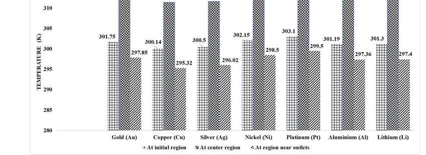
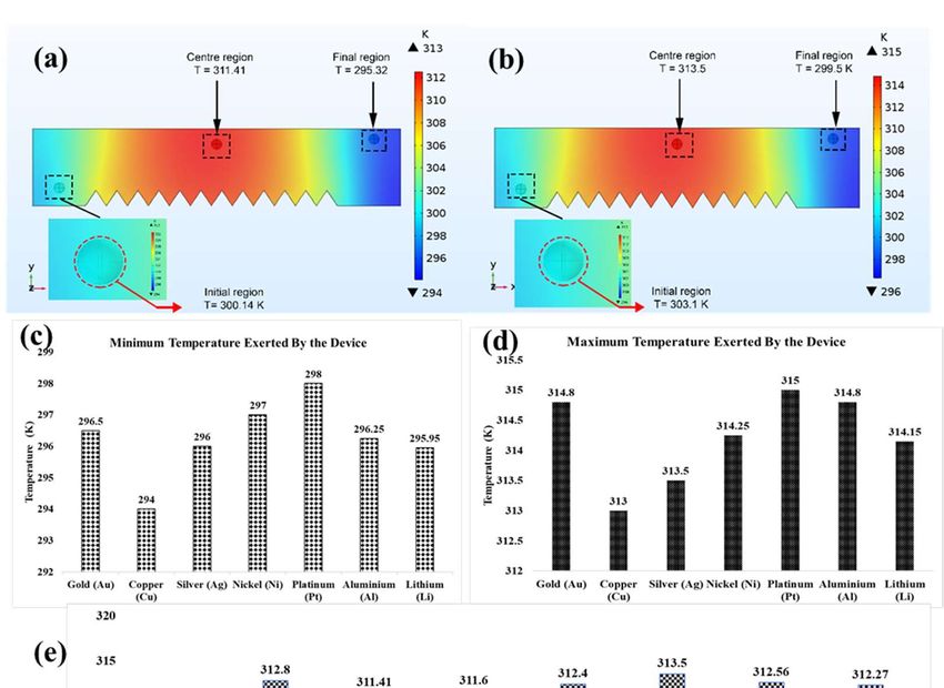
Preprints (www.preprints.org) | NOT PEER-REVIEWED | Posted: 25 May 2021 doi:10.20944/preprints202105.0591.v1

 11 of 20

 Table 3. Temperature exerted by cell at centre region at different electric potential.

 Temperature exerted at
 Applied Electric Potential Cell Viability
 Centre region (in kelvin)
 5 100% Viable 313
 10 Suffers lethal injury 466
 15 lethal injury, Cell death 752
 25 lethal injury, Cell death 1533
 40 lethal injury, Cell death 2367

 Final region (near to the outlet) receives lowest thermal gradient. As a result the cells
 entering in this region are subjected to low thermal effects compared to other regions.
 Under applied potential of 5V, the temperature in this region is found to be 294K estab-
 lishing safer temperature zone for the cells to be viable. These cells remains healthy at the
 outlet bins. At 10V, the region has minimum temperature of 404K leading the cells to
 undergo lethal injury. With a further increase to 15V, 25V, and 40V the temperature in
 this region drastically increases to 606.5K, 1158K, 2005K resulting in cell death.

 Table 4. Temperature exerted by cell at final region at different electric potential.

 Temperature exerted at
 Applied Electric Potential Cell Viability
 Final region (in kelvin)
 5 100% Viable 294
 10 Suffers lethal injury 404
 15 lethal injury, Cell death 606.5
 25 lethal injury, Cell death 1158
 40 lethal injury, Cell death 2005

 When the applied electric potential is increased the cell viability gets reduced as they are
 exposed to high thermal effect. Irrespective of the time period it is exposed to it. Selection
 of applied electric potential directly influences thermal impact on the cells. The temper-
 ature exposure offers a consistent understanding of cell viability. However, the applied
 potential of 5V to the device results in 100% viability of the cells.

 3.3.Effect of Electrode material
 Material such as Gold, copper, silver, nickel, platinum and aluminium are mainly used as
 electrode in microfluidic devices [51]. The parameters including electrical conductivity,
 coefficient of thermal expansion, density and thermal conductivity is modelled accord-
 ingly and listed in table (5) . All the materials were chosen from COMSOL Multiphysics
 library. The thermal effect on the cells for cell viability was tested and temperature gen-
 erated in device using these material was contrasted for device reliability. The distribu-
 tion of temperature varies accordingly with the region. The minimum temperature ex-
 erted by the device is shown in Figure 5(c). Copper exerts lowest temperature of 294 K on
 the device. Platinum and Gold exerts temperature of 315 K and 314.8 K which is recorded
 has maximum temperature under the applied electric potential 5V. The maximum
 temperature exposed by the various material is shown in Figure 5(d). The applied elec-
 trode potential of 5 V was initially kept throughout the simulation. The temperature
 generated on the cells varies from one material to another.
Preprints (www.preprints.org) | NOT PEER-REVIEWED | Posted: 25 May 2021 doi:10.20944/preprints202105.0591.v1

 12 of 20

 Table 5. Material properties of various metal electrodes

 Electrode material Electrical conductivity Coefficient of thermal
 [S/m] expansion
 [1/K]
 Aluminium 35.5e6 23.1e-6
 Gold 45.6e6 14.2e-6
 Copper 58.1e6 16.5e-6
 Silver 61.6e6 18.9e-6
 Nickel 13.8e6 8.80e-6
 Platinum 8.9e6 8.80e-6
 Aluminium 35.5e6 23.1e-6
 The commonly used electrodes in microfluidics include platinum, gold due to its
 inertness, conductivity and malleability. All the material was tested under the same ap-
 plied electric potential. The temperature exerted by the cells using copper electrode is
 shown in Figure 5(a). Temperature exerted due to platinum electrode is shown in Figure
 5(b). Gold and platinum resulted a temperature rise of approximately 1 to 1.5 kelvin rel-
 ative to other materials. Gold and platinum electrode recorded highest thermal effect on
 the cells with temperature of 312.80 K and 313.5 K at the centre region. At the region near
 the outlets the temperature on the cells due to this electrode was found to be 297.85 K and
 299.5 K. Even though, these material has unique withstanding property at higher tem-
 perature. The cost makes it undesirable for many applications. If a cell is meant to be
 exposed to the greater time period, then these materials are highly suitable for their
 toughness. Aluminium and lithium confronts the temperature of 301.19 K and 301.30 K at
 initial region. While copper and silver electrode experienced very low temperature at in-
 itial region as much as 300.14 K and 300.50 K but at the centre region the copper exposes
 the temperature as high as 311.41K and silver exposes the temperature of 311.6 K. The
 comparative plot of temperature exerted by cell by different electrode material is shown
 in Figure 5(e). This temperature remains safer for the cell in preventing them from cell
 injury or cell death. At the region near outlet, copper material exposes the temperature of
 295.32 K on the cells while silver results with 296.02 K temperature on the device.

 Table 6: Temperature exerted by cell in all three region at applied electric potential of 10 V using
 different electrode materials

 Applied Electrode Temperature Temperature Temperature
 Electrode material Exerted in Initial Exerted in centre Exerted in Final
 potential region region region
 (in kelvin) (in kelvin) (in kelvin)
 10 Gold 425.13 417.8 406.75
 10 Copper 423.52 416.41 405.61
 10 Silver 423.88 416.6 405.95
 10 Nickel 425.53 417.4 407.35
 10 Platinum 426.48 418.7 408.20
 10 Aluminium 424.57 417.56 406.19
 10 Lithium 424.68 417.27 406.3
Preprints (www.preprints.org) | NOT PEER-REVIEWED | Posted: 25 May 2021 doi:10.20944/preprints202105.0591.v1

 13 of 20

 The thermal distribution in all the three region using different electrode material is
 listed in table (6).It is noted that, copper produces least temperature distribution of
 around 405.61 K while the use of platinum electrode material results increased temper-
 ature distribution of 408.20K. Major variation of 1K to 2.5K is noted in material like gold,
 nickel, platinum , aluminium, lithium compared to copper electrode . This material are
 often employed when there is need for multiple runs.

 Figure 5. (a) Thermal effects on cell due to copper electrode. (b) Thermal effects on cell due to
 platinum electrode. (c) Minimum temperature plot of different electrode material on device. (d)
 Maximum temperature plot of different electrode material on device.
 Aluminium and lithium exposes the temperature of 312.6K and 312.27K in the
 centre region and at the region near the outlets the cell gets experienced to the tempera-
 ture of 297.36K and 297.4K. However, when lithium reacts with organic solvent (PBS
 solution) for long period of time it becomes thermally unstable [52]. Nickel records the
 temperature of 298.5K at the region near the outlets and higher temperature of 312.4K at
 centre region. The thermal effect on the cell at this voltage will often result in lethal in-
 jury, when further increased to 25V and 40V, the reliability of the device is weakened as
 the temperature increases closer to its boiling point. The use of both copper and silver is
 highly preferable in this case making it a suitable material for low-cost microfluidic de-
 vice manufacturing.
Preprints (www.preprints.org) | NOT PEER-REVIEWED | Posted: 25 May 2021 doi:10.20944/preprints202105.0591.v1

 14 of 20

 3.4. Effect of substrate material

 The impact of technologically important substrate material on the cell of interest was
 examined. Glass is mainly used in microfluidics for its beneficial optical characteristics,
 stability[53]. Heat distribution in glass remains uniform unlike any other substrate ma-
 terial[54] . It is noted that the substrate material which has high thermal conductivity are
 more likely to damage the cells. The cells were analysed on all the three regions. Sub-
 strate material like PDMS (polydimethylsiloxane), PMMA (Polymethylmethacrylate),
 polyimide, glass was analysed using the simulation. Material properties of each of the
 substrate has been listed in the below table (7).

 Table 7: Material properties of substrate material

 Parameters PDMS PMMA Polyimide Glass
 Thermal Conductivity[1,2][W/(m·K)] 0.16 0.19 0.15 0.8
 Electrical conductivity[3][S/m] 0.25 0.25 0.5 0.5
 Density[4–6] [kg/m³] 970 1190 1300 2329
 Relative permittivity 2.75 3.0 1 11.7
 Heat capacity at constant temperature 1460 1420 1100 700
 [J/(kg·K)]
 Youngs modulus [Pa] 750e2 3e9 3.1e9 170e9
 Poisson’s ratio 0.49 0.40 1 0.28
 Coefficient of thermal expansion[1/K] 9e-4 70e-6 9e-6 2.6e-6

 Figure 6.(a) Thermal effects on cells at 5V using PMMA material. (b) Thermal effects on cells at 5V
 using glass material. (c) Maximum temperature exerted on the device at 5 V. (d) Maximum tem-
 perature exerted on the device at 10 V

 The thermal effect on the cell using PMMA material is shown in Figure 6(a). At the initial
 region the cells gets exposed to the temperature of 295.32K and 311.41K is exerted at
 centre region. In the region near the outlet the temperature exerted is 300.14K. The tem-
 perature exerted by cells using glass substrate material is found to be in the range of
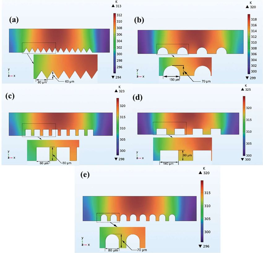
Preprints (www.preprints.org) | NOT PEER-REVIEWED | Posted: 25 May 2021 doi:10.20944/preprints202105.0591.v1

 15 of 20

 295.24K to 295.34K as shown in Figure 6(b). Under 5V, all these material exerted the
 thermal effects within the threshold limit of 330K. The cells undergoes lethal injury when
 it is exposed to temperature more than 316.25K. PDMS material generated minimal
 temperature of 316K. Use of PDMS is restricted for prolonged cell separation as it is
 high hydrophobicity can absorb some bio molecules [61]. Aging of these material also
 changes its mechanical properties yielding biased results [62].

 Polyimide exerts the temperature of 297.15 K at the region near the outlet and 302.82
 K at the initial region. The temperature exerted at the centre region is found to be 314.71
 K. The temperature exerted due to different substrate material at 5 V is shown in Figure
 6(c). The maximum temperature more than 440 K is exerted on the device due to different
 substrate material at 10 V is shown in Figure 6(d). Polyimide serves an emerging sub-
 strate material with high chemical resistance, much biocompatible with high dielectric
 constant[63,64]. However, these substrate material is not suitable for commercial purpose
 as it has low impact strength and remains expensive. PMMA is less expensive, more rigid
 ,has compatibility to many biological application[65].

 3.5.Effect of Electrode Geometry

 The thermal effects generated by different electrode shape was examined for device re-
 liability. In an DEP based microfluidic devices, electrode geometry plays a vital role in
 producing non-uniform electric field as gradient of electric field influences the DEP per-
 formance[40]. Various electrode shape like square, triangle, rectangle, rectangle with soft
 edges and square with soft edges was examined.

 Figure 7. Dimension of various electrode geometry. (a) triangular shaped electrode (b) rectangle
 with soft edges electrode. (c) rectangle shaped electrode. (d) square shaped electrode. (e) square
 shaped with soft edges electrode.
Preprints (www.preprints.org) | NOT PEER-REVIEWED | Posted: 25 May 2021 doi:10.20944/preprints202105.0591.v1

 16 of 20

 Triangular shaped electrode has height of 60 µm and width of 80 µm as shown in Figure
 7(a). Rectangle with soft edges has height of 70 µm and width of 150 µm while rectangle
 shaped is of 140 µm width and 80 µm height represented in Figure 7(b) and Figure 7(c).
 Square shaped electrode is of 80 µm height and width and Square shaped electrode
 with soft edges is of 80 µm width and 70 µm height as shown in Figure 7(d) and Figure
 7(e). The edges are carved with the radius of 40 µm. Electrode geometry not only helps
 in regulating strength of non-uniform electric field but also to facilitate fabrication.

 The thermal effects on both cell and to the device due to the electrode geometry will
 be different. We investigated temperature generated on the device on all the three re-
 gions. The temperature at the region near to outlet (final region) received a low temper-
 ature, the triangular shaped electrode exploits very low temperature as much as 294 K on
 the device. While square shaped electrode exposed a temperature of 298 K while square
 shaped with soft edge exposed a temperature of 296K. Rectangular shaped electrode ex-
 erted temperature of 300K compared to all other electrode geometry. Rectangular with
 soft edges exerts temperature of 299K. At initial region temperature of 295.32K is ex-
 posed with triangular electrode. Square shape and square shaped with soft edged elec-
 trode exerts the temperature of 297.23K and 299.95K. While rectangle and rectangular
 shaped electrode result with temperature rise of 301.24K and 302.25K.

 Table 8. Temperature generated across the three region on different electrode geometry with ap-
 plied electric potential of 10V.

 Minimum Maximum
 Temperature
 temperature on the temperature on the
 at initial
 Electrode Geometry device device
 region
 (at near the outlet) (At center region)
 (in kelvin)
 (in kelvin) (in kelvin)
 Triangular 405.61 465.72 423.52

 Square shaped with soft edges 407.53 468.25 425.25

 Square shaped 410.56 472.32 426.50
 Rectangle with soft edges 412.10 474.25 428.35
 Rectangle shaped 413.36 478.05 431.25
 Compared to other region, the cell has a high temperature in the centre region. The
 maximum temperature of 322.25K received by the cell is with rectangle shaped electrode.
 The cell undergo lethal injury as it exceeds threshold temperature. The triangular elec-
 trode exposes the temperature of 311.4K on the cells , however the cells remains viable.
 The square shaped with soft edges and rectangle shaped with edges electrode exerts
 temperature of 314.50K and 318.25K on the cells. In this case, the cell remains remain
 viable with square shaped with soft edges. Triangular electrode has a single sharp edge
 that concentrates a strong electrical field only at that location. The tip and dimension the
 electrode causes strong gradient in non-uniform electric field[66]. Thus, each electrode
 shape will have distinct region of electric field. As a result, the dimension of square
 shaped and rectangle shaped electrode results in strong gradient of electric field com-
 pared to other electrode geometry. The temperature exerted by the cell at different region
 at applied electric potential of 10V is listed in table (8). In order to check device reliabil-
 ity the electrodes were tested under with 5V,10V, 15V, 25V, 40V. The maximum temper-
 ature exerted by the electrode is shown in Figure 8. The thermal effects generated using
 triangular electrode never impacts injury on the cells when analysed at 5V.
Preprints (www.preprints.org) | NOT PEER-REVIEWED | Posted: 25 May 2021 doi:10.20944/preprints202105.0591.v1

 17 of 20

 Figure 8. Maximum temperature exerted on the device (a) at applied electric potential of 5V. (b) at
 applied electric potential of 10V. (c) at applied electric potential of 15V. (d) at applied electric po-
 tential of 25V. (e) at applied electric potential of 40V.

 In all cases when the applied voltage is varied accordingly, the thermal effect on the tri-
 angular electrode is low compared to other electrode. This makes it suitable electrode for
 fabrication of device. While other electrode at the same applied potential results in in-
 crease of temperature of about 10K to 15K compared to triangular electrode. This makes
 it reliable compared to all other electrode geometry.

 4. Conclusion
 This papers illustrates the thermal exposure on the cells and device due to joule
 heating in an electrode based dielectrophoretic devices. Thermal variation generated by
 using different parameters like electrode material, electrode geometry, substrate materi-
 al, buffer conductivity of the medium, applied electric potential was investigated at room
 temperature. Minimum temperature distribution is found at the outlet region whereas,
 the maximum temperature distribution occurs at the region of strong thermal gradient
 (in center region). The cells remains viable to the maximum time of 1.45 seconds with
 buffer conductivity of 10 [mS/m] with 5V which is quiet enough for trapping healthy cells
 in the outlet bins in an microfluidic device. However, survival time of the cells inside
 the microchannel was found to be decreasing with the increase in applied electric poten-
 tial with buffer conductivity in the range of 10[mS/m] to 55[mS/m]. Furthermore, the in-
 crease in buffer conductivity also contributes increased joule heating that eventually
 leads to more heat generated on the cells that may cause cell death. In our case study for
Preprints (www.preprints.org) | NOT PEER-REVIEWED | Posted: 25 May 2021 doi:10.20944/preprints202105.0591.v1

 18 of 20

 DEP based cell separation application, we observed that, the device material fabricated
 using PMMA substrate and electrode with triangular geometry arrangements are po-
 tential to generate least amount of joule heating compare to other electrode arrangements
 resulting in perfect separation of cells ensuring the cells remains viable. The proposed
 triangular electrode arrangements with copper material are very rich in generating low
 thermal gradient which regulates high temperature at the tip of electrode region rather
 than any other portion of the device in case of single run. Gold and platinum electrode
 material remain effective for many runs, as the main channel does not darken in this case.
 Thermal damage to cells using a triangular electrode is less than any other electrode
 geometry with a applied potential in range of 10V to 40V which makes it suitable to use
 in all electrode based dielectrophoretic devices. Hence, our proposed guidelines will
 enable the researcher to design microfluidic devices without relying on complex process
 in order to minimize the joule heating effect inside the microchannel. The proposed pa-
 rameters are more efficient in collecting healthy cells at the outlet bins with minimized
 joule heating in all DEP based devices.

 Funding: The authors gratefully acknowledge the Deanship of Scientific Research, King Khalid
 University (KKU), Abha-Asir, Kingdom of Saudi Arabia for funding this research work under the
 grant number R.G.P.2/89/41.

 Author Contributions: C.M.Y. and M.Z.A. contributed equally to this work; K.I. and A.A
 obtained funding for the project; K.I. and S.I. reviewed and edited the paper; M.Y.C. and
 M.Z.A. performed the simulation and analyzed the results. All authors wrote the paper.
 All authors have read and agreed to the published version of the manuscript.
 Acknowledgement: The authors gratefully acknowledge the Deanship of Scientific Research, King
 Khalid University (KKU), Abha-Asir, Kingdom of Saudi Arabia for funding this research work
 under the grant number R.G.P.2/89/41. CMY and MZA thanks Research and Development Labor-
 atory, ECE, C. Abdul Hakeem College of Engineering and Technology, Melvisharam for providing
 support to carry out this research project.
 Conflicts of Interest: The authors declare no conflict of interest.

 References

 1. N.A. Rahman, F. Ibrahim, B. Yafouz, Dielectrophoresis for biomedical sciences applications: A review, Sensors (Switzer-
 land). 17 (2017).
 2. H. Yan, H. Wu, Joule Heating and Chip Materials, in: Encycl. Microfluid. Nanofluidics, Springer US, 2014: pp. 1–15.
 3. M. Punjiya, H.R. Nejad, J. Mathews, M. Levin, S. Sonkusale, A flow through device for simultaneous dielectrophoretic cell
 trapping and AC electroporation, Sci. Rep. 9 (2019), pp.1–11.
 4. G. Velve-Casquillas, M. Le Berre, M. Piel, P.T. Tran, Microfluidic tools for cell biological research, Nano Today. 5 (2010),
 pp.28–47.
 5. A. Valero, T. Braschler, N. Demierre, P. Renaud, A miniaturized continuous dielectrophoretic cell sorter and its applica-
 tions, Biomicrofluidics. 4 (2010).
 6. T.M. Pearce, J.A. Wilson, S.G. Oakes, S.Y. Chiu, J.C. Williams, Integrated microelectrode array and microfluidics for tem-
 perature clamp of sensory neurons in culture, Lab Chip. 5 (2005), pp.97–101.
 7. J. Wang, Y. Wei, S. Zhao, Y. Zhou, W. He, Y. Zhang, W. Deng, The analysis of viability for mammalian cells treated at
 different temperatures and its application in cell shipment, PLoS One. 12 (2017), pp.1–16.
 8. S. Chen, Z. Wang, X. Cui, L. Jiang, Y. Zhi, X. Ding, Z. Nie, P. Zhou, D. Cui, Microfluidic Device Directly Fabricated on
 Screen-Printed Electrodes for Ultrasensitive Electrochemical Sensing of PSA, Nanoscale Res. Lett. 14 (2019), pp. 0–6.
 9. L. Chen, X. Liu, X. Zheng, X. Zhang, J. Yang, T. Tian, Y. Liao, Dielectrophoretic separation of particles using microfluidic
 chip with composite three-dimensional electrode, Micromachines. 11 (2020).
 10. G. Kunti, J. Dhar, A. Bhattacharya, S. Chakraborty, Joule heating-induced particle manipulation on a microfluidic chip,
 Biomicrofluidics. 13 (2019).
 11. A. Kausar, R. Taherian, Effect of external fields on electrical conductivity of polymer-based composites, Elsevier Inc., (2018).
 12. S.H. Song, B.S. Kwak, J.S. Park, W. Kim, H. IL Jung, Novel application of Joule heating to maintain biocompatible tem-
 peratures in a fully integrated electromagnetic cell sorting system, Sensors Actuators, A Phys. 151 (2009), pp.64–70.
 13. B. Del Rosal, C. Sun, D.N. Loufakis, C. Lu, D. Jaque, Thermal loading in flow-through electroporation microfluidic devices,
 Lab Chip. 13 (2013), pp.3119–3127.
Preprints (www.preprints.org) | NOT PEER-REVIEWED | Posted: 25 May 2021 doi:10.20944/preprints202105.0591.v1

 19 of 20

 14. G.Y. Tang, D.G. Yan, C. Yang, H.Q. Gong, C.J. Chai, Y.C. Lam, Joule heating and its effects on electroosmotic flow in mi-
 crofluidic channels, J. Phys. Conf. Ser. 34 (2006), pp.925–930.
 15. J. Vlassakis, A.E. Herr, Joule Heating-Induced Dispersion in Open Microfluidic Electrophoretic Cytometry, Anal. Chem. 89
 (2017), pp.12787–12796.
 16. E.O. Adekanmbi, S.K. Srivastava, Dielectrophoretic applications for disease diagnostics using lab-on-a-chip platforms, Lab
 Chip. 16 (2016), pp.2148–2167.
 17. D.R. Albrecht, R.L. Sah, S.N. Bhatia, Geometric and material determinants of patterning efficiency by dielectrophoresis,
 Biophys. J. 87 (2004), pp.2131–2147.
 18. B.I.M.Z. Ansar, V. Tirth, C.M. Yousuff, N.K. Shukla, S. Islam, K. Irshad, K.O.M. Aarif, Simulation Guided Microfluidic
 Design for Multitarget Separation Using Dielectrophoretic Principle, Biochip J. 14 (2020), pp.390–404.
 19. Z.T.F. Yu, K.M. Aw Yong, J. Fu, Microfluidic blood cell sorting: Now and beyond, Small. 10 (2014), pp.1687–1703.
 20. M.H. Wang, W.H. Chang, Effect of electrode shape on impedance of single HeLa cell: A COMSOL simulation, Biomed Res.
 Int. 2015 (2015).
 21. M.B. Fox, D.C. Esveld, A. Valero, R. Luttge, H.C. Mastwijk, P. V. Bartels, A. Van Den Berg, R.M. Boom, Electroporation of
 cells in microfluidic devices: A review, Anal. Bioanal. Chem. 385 (2006), pp.474–485.
 22. M. Dewhirst, B.L. Viglianti, M. Lora-Michiels, P.J. Hoopes, M.A. Hanson, Thermal dose requirement for tissue effect: ex-
 perimental and clinical findings, in: Therm. Treat. Tissue Energy Deliv. Assess. II, SPIE, (2003), p. 37.
 23. B. Sarno, D. Heineck, M.J. Heller, S. Ibsen, Dielectrophoresis: Developments and applications from 2010 to 2020, Electro-
 phoresis. (2020), pp.1–54.
 24. R. Pethig, Dielectrophoresis: An assessment of its potential to aid the research and practice of drug discovery and delivery,
 Adv. Drug Deliv. Rev. 65 (2013), pp.1589–1599.
 25. C.M. Yousuff, E.T.W. Ho, K. Ismail Hussain, N.H.B. Hamid, Microfluidic platform for cell isolation and manipulation
 based on cell properties, Micromachines. 8 (2017), pp.1–26.
 26. M.Z. Rashed, N.G. Green, S.J. Williams, Scaling law analysis of electrohydrodynamics and dielectrophoresis for isomotive
 dielectrophoresis microfluidic devices, Electrophoresis. 41 (2020), pp.148–155.
 27. M.-H. Wang, W.-H. Chang, Effect of Electrode Shape on Impedance of Single HeLa Cell: A COMSOL Simulation., Biomed
 Res. Int. 2015 (2015), pp.871603.
 28. J. Zhang, Z. Song, Q. Liu, Y. Song, Recent advances in dielectrophoresis-based cell viability assessment, Electrophoresis. 41
 (2020), pp.917–932.
 29. R. Pethig, Dielectrophoresis: Status of the theory, technology, and applications, Biomicrofluidics. 4 (2010), pp.1–35.
 30. C. Qian, H. Huang, L. Chen, X. Li, Z. Ge, T. Chen, Z. Yang, L. Sun, Dielectrophoresis for bioparticle manipulation, Int. J.
 Mol. Sci. 15 (2014), pp.18281–18309.
 31. D. Erickson, D. Sinton, D. Li, Joule heating and heat transfer in poly(dimethylsiloxane) microfluidic systems, Lab Chip. 3
 (2003), pp.141–149.
 32. R. Chein, Y.C. Yang, Y. Lin, Estimation of Joule heating effect on temperature and pressure distribution in electrokinet-
 ic-driven microchannel flows, Electrophoresis. 27 (2006), pp.640–649.
 33. O.T. Nedelcu, A thermal study on joule-heating induced effects in dielectrophoretic microfilters, Rom. J. Inf. Sci. Technol. 14
 (2011), pp.309–323.
 34. Y. Zhu, S. Nahavandi, A. Bui, K. Petkovic-Duran, Joule heating in polymer microfluidic chip, in: BioMEMS Nanotechnol. II,
 (2005), pp. 603612
 35. T. Brans, F. Strubbe, C. Schreuer, S. Vandewiele, K. Neyts, F. Beunis, Joule heating monitoring in a microfluidic channel by
 observing the Brownian motion of an optically trapped microsphere, Electrophoresis. 36 (2015), pp.2102–2109.
 36. X.B. Wang, J. Yang, Y. Huang, J. Vykoukal, F.F. Becker, P.R.C. Gascoyne, Cell separation by dielectrophoretic
 field-flow-fractionation, Anal. Chem. 72 (2000), pp.832–839.
 37. R.S.W. Thomas, P.D. Mitchell, R.O.C. Oreffo, H. Morgan, N.G. Green, Image-based sorting and negative dielectrophoresis
 for high purity cell and particle separation, Electrophoresis. 40 (2019), pp.2718–2727.
 38. A. Salari, M. Navi, T. Lijnse, C. Dalton, AC electrothermal effect in microfluidics: A review, Micromachines. 10 (2019).pp. 1–
 27.
 39. C.M. Yousuff, N.H.B. Hamid, K.I. Hussain, E.T.W. Ho, Numerical modelling and simulation of dielectrophoretic based
 WBC sorting using sidewall electrodes, in: Int. Conf. Intell. Adv. Syst. ICIAS 2016, 2017: pp. 1–5.
 40. H. Zhang, H. Chang, P. Neuzil, DEP-on-a-chip: Dielectrophoresis applied to microfluidic platforms, Micromachines. 10
 (2019).
 41. M.S. Jaeger, T. Mueller, T. Schnelle, Thermometry in dielectrophoresis chips for contact-free cell handling, J. Phys. D. Appl.
 Phys. 40 (2007), pp.95–105.
 42. T. Jiang, Y. Ren, W. Liu, D. Tang, Y. Tao, R. Xue, H. Jiang, Dielectrophoretic separation with a floating-electrode array
 embedded in microfabricated fluidic networks, Phys. Fluids. 30 (2018).
 43. H. Chen, B. Cao, B. Sun, Y. Cao, K. Yang, Y.S. Lin, H. Chen, Highly-sensitive capture of circulating tumor cells using mi-
 cro-ellipse filters, Sci. Rep. 7 (2017), pp.1–10.
 44. J. Fildes, S. Fisher, C.M. Sheaff, J.A. Barrett, Effects of short heat exposure on human red and white blood cells, J. Trauma -
 Inj. Infect. Crit. Care. 45 (1998), pp.479–484.
Preprints (www.preprints.org) | NOT PEER-REVIEWED | Posted: 25 May 2021 doi:10.20944/preprints202105.0591.v1

 20 of 20

 45. B.J. Wood, J.R. Ramkaransingh, T. Fojo, M.M. Walther, S.K. Libutti, Percutaneous tumor ablation with radiofrequency,
 Cancer. 94 (2002), pp.443–451.
 46. S.H. Beachy, E.A. Repasky, Toward establishment of temperature thresholds for immunological impact of heat exposure
 in humans, Int. J. Hyperth. 27 (2011), pp.344–352.
 47. S. McDermott, D.A. Gervais, Radiofrequency ablation of liver tumors, Semin. Intervent. Radiol. 30 (2013), pp.49–55..
 48. M.Z. Ansar, M.Y. Caffiyar, A. Mohammed Kashif, Microfluidic device for Multitarget separation using DEP techniques
 and its applications in clinical research, in: 2020 6th Int. Conf. Bio Signals, Images, Instrumentation, ICBSII 2020, Institute of
 Electrical and Electronics Engineers Inc., (2020).
 49. S. Sridharan, J. Zhu, G. Hu, X. Xuan, Joule heating effects on electroosmotic flow in insulator-based dielectrophoresis,
 Electrophoresis. 32 (2011), pp. 2274–2281
 50. M. Kim, S. Mo Jung, K.H. Lee, Y. Jun Kang, S. Yang, A microfluidic device for continuous white blood cell separation and
 lysis from whole blood, Artif. Organs. 34 (2010), pp.996–1002.
 51. C. Birch, J.P. Landers, Electrode materials in microfluidic systems for the processing and separation of DNA: A mini re-
 view, Micromachines. 8 (2017), pp.1–14.
 52. Y. Yuan, K. Amine, J. Lu, R. Shahbazian-Yassar, Understanding materials challenges for rechargeable ion batteries with in
 situ transmission electron microscopy, Nat. Commun. 8 (2017), pp.1–14.
 53. M.R. Haq, Y.K. Kim, J. Kim, J. Ju, S.M. Kim, Fabrication of all glass microfluidic device with superior chemical and me-
 chanical resistances by glass molding with vitreous carbon mold, J. Micromechanics Microengineering. 29 (2019).
 54. D. Attinger, C. Frankiewicz, A.R. Betz, T.M. Schutzius, R. Ganguly, A. Das, C.-J. Kim, C.M. Megaridis, Surface engineering
 for phase change heat transfer: A review, MRS Energy Sustain. 1 (2014), pp.1–40.
 55. J. Wei, M. Liao, A. Ma, Y. Chen, Z. Duan, X. Hou, M. Li, N. Jiang, J. Yu, Enhanced thermal conductivity of polydime-
 thylsiloxane composites with carbon fiber, Compos. Commun. ,17, (2020), pp.141–146.
 56. I. Donmez Noyan, M. Dolcet, M. Salleras, A. Stranz, C. Calaza, G. Gadea, M. Pacios, A. Morata, A. Tarancon, L. Fonseca,
 All-silicon thermoelectric micro/nanogenerator including a heat exchanger for harvesting applications, J. Power Sources.
 413 (2019), pp.125–133.
 57. Z. Han, A. Fina, Thermal conductivity of carbon nanotubes and their polymer nanocomposites: A review, Prog. Polym.
 Sci. 36 (2011) 914–944. https://doi.org/10.1016/j.progpolymsci.2010.11.004.
 58. T.H.N. Dinh, E. Martincic, E. Dufour-Gergam, P.Y. Joubert, Mechanical characterization of PDMS films for the optimiza-
 tion of polymer based flexible capacitive pressure microsensors, J. Sensors. (2017).
 59. R.I. Acosta, K.C. Gross, G.P. Perram, Thermal degradation of Poly(methyl methacrylate) with a 1.064 µm Nd:YAG laser in
 a buoyant flow, Polym. Degrad. Stab. 121 (2015), pp.78–89.
 60. S. Sathya, M. Pavithra, S. Muruganand, Simulation of Electrostatic Actuation in Interdigitated Comb Drive MEMS Reso-
 nator for Energy Harvester Applications, IOP Conf. Ser. Mater. Sci. Eng. 149 (2016).
 61. S. Halldorsson, E. Lucumi, R. Gómez-Sjöberg, R.M.T. Fleming, Advantages and challenges of microfluidic cell culture in
 polydimethylsiloxane devices, Biosens. Bioelectron. 63 (2015), pp.218–231.
 62. A.L. Paguirigan, D.J. Beebe, From the cellular perspective: Exploring differences in the cellular baseline in macroscale and
 microfluidic cultures, Integr. Biol. 1 (2009), pp.182–195
 63. R.R. Richardson, J.A. Miller, W.M. Reichert, Polyimides as biomaterials: preliminary biocompatibility testing, Biomaterials.
 14 (1993), pp. 627–635.
 64. C.P. Constantin, M. Aflori, R.F. Damian, R.D. Rusu, Biocompatibility of polyimides: A mini-review, Materials (Basel). 12
 (2019).
 65. U. Ali, K.J.B.A. Karim, N.A. Buang, A Review of the Properties and Applications of Poly (Methyl Methacrylate) (PMMA),
 Polym. Rev. 55 (2015), pp. 678–705.
 66. V. Gill, P.R. Guduru, B.W. Sheldon, Electric field induced surface diffusion and micro/nano-scale island growth, Int. J.
 Solids Struct. 45 (2008), pp.943–958.
You can also read