Highly Selective and pH-Stable Reverse Osmosis Membranes Prepared via Layered Interfacial Polymerization
←
→
Page content transcription
If your browser does not render page correctly, please read the page content below
membranes

Article
Highly Selective and pH-Stable Reverse Osmosis Membranes
Prepared via Layered Interfacial Polymerization
Min-Gyu Shin, Wansuk Choi *                    and Jung-Hyun Lee *

                                          Department of Chemical and Biological Engineering, Korea University, 145 Anam-ro, Seongbuk-gu,
                                          Seoul 02841, Korea; aaas45@korea.ac.kr
                                          * Correspondence: plokmiju@korea.ac.kr (W.C.); leejhyyy@korea.ac.kr (J.-H.L.)

                                          Abstract: Ultrathin and smooth polyamide (PA) reverse osmosis (RO) membranes have attracted
                                          significant interest due to their potential advantages of high permeance and low fouling propensity.
                                          Although a layered interfacial polymerization (LIP) technique aided by the insertion of a polyelec-
                                          trolyte interlayer has proven effective in fabricating ultrathin and uniform membranes, the RO
                                          performance and pH stability of the fabricated LIP membrane remain inadequate. In this study,
                                          a poly(piperazineamide) (PIPA) layer prepared via interfacial polymerization (IP) was employed
                                          as an interlayer to overcome the limitations of the prototype LIP method. Similar to the control
                                          polyelectrolyte-interlayered LIP membrane, the PIPA-interlayered LIP (pLIP) membrane had a much
                                          thinner (~20 nm) and smoother selective layer than the membrane fabricated via conventional IP
                                          due to the highly surface-confined and uniform LIP reaction. The pLIP membrane also exhibited
                                          RO performance exceeding that of the control LIP and conventional IP-assembled membranes, by
                                          enabling denser monomer deposition and a more confined interfacial reaction. Importantly, the chem-
                                          ically crosslinked PIPA interlayer endowed the pLIP membrane with higher pH stability than the
                                          control polyelectrolyte interlayer. The proposed strategy enables the fabrication of high-performance

                                   and pH-stable PA membranes using hydrophilic supports, which can be applied to other separation
Citation: Shin, M.-G.; Choi, W.; Lee,
                                          processes, including osmosis-driven separation and organic solvent filtration.
J.-H. Highly Selective and pH-Stable
Reverse Osmosis Membranes                 Keywords: reverse osmosis; desalination; water treatment; thin film composite membrane; interfacial
Prepared via Layered Interfacial          polymerization; layered interfacial polymerization; interlayer; pH stability
Polymerization. Membranes 2022, 12,
156. https://doi.org/10.3390/
membranes12020156
                                          1. Introduction
Academic Editor: Boguslaw Kruczek
                                               Environmental pollution and freshwater shortages have become critical global chal-
Received: 22 December 2021
                                          lenges in modern society. To cope with these issues, technologies for producing clean
Accepted: 26 January 2022
                                          water, including distillation, ion exchange, and membrane filtration, have been extensively
Published: 27 January 2022
                                          developed and refined [1]. In particular, considerable advances in the reverse osmosis
Publisher’s Note: MDPI stays neutral      (RO) membrane process have secured its position as the most commonly used desalination
with regard to jurisdictional claims in   technology, due to its low energy footprint and high-throughput productivity [2]. In the
published maps and institutional affil-   RO process, a semi-permeable RO membrane plays a pivotal role in water purification by
iations.                                  discriminating dissolved salts from saline water under high-pressure conditions [3].
                                               Conventional RO membranes have a thin-film-composite (TFC) structure composed
                                          of a porous polymeric support and a dense polyamide (PA) selective layer [4]. The PA
                                          selective layer is typically synthesized via interfacial polymerization (IP) of two monomers,
Copyright: © 2022 by the authors.
                                          m-phenylenediamine (MPD) and trimesoyl chloride (TMC), dissolved in immiscible wa-
Licensee MDPI, Basel, Switzerland.
                                          ter and an organic solvent, respectively [5,6]. This IP process enables the fabrication of
This article is an open access article
                                          TFC membranes with reliable RO performance in a scalable and fast manner. However,
distributed under the terms and
                                          it produces an inherently heterogeneous, relatively thick, and rough PA structure with
conditions of the Creative Commons
Attribution (CC BY) license (https://
                                          ridge-and-valley and/or nodular surface features [7], which hampers our fundamental un-
creativecommons.org/licenses/by/
                                          derstanding of the structure-performance relationship of the membrane. Furthermore, the
4.0/).

Membranes 2022, 12, 156. https://doi.org/10.3390/membranes12020156                                     https://www.mdpi.com/journal/membranes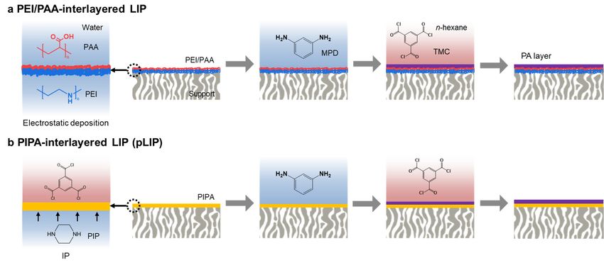
Membranes 2022, 12, 156                                                                                            2 of 13

                          inherent PA structure formed by conventional IP is unfavorable and impractical for achiev-
                          ing high water permeation and resisting membrane fouling [8–10]. Numerous efforts have
                          been dedicated to the formation of a smooth, homogeneous, and ultrathin PA layer by em-
                          ploying new fabrication strategies, including molecular layer-by-layer [9,11], support-free
                          IP [12,13], electrospraying [14,15], and dual-slot coating [16,17]. Although all the pro-
                          posed strategies formed a smooth and ultrathin PA layer with good RO performance, they
                          required labor-intensive protocols [18] and/or expensive experimental facilities [14,15].
                                Our research group has devised a new facile method to fabricate a smooth, uniform,
                          and ultrathin PA layer, referred to as a layered IP (LIP) technique [19]. The LIP strategy
                          relies on the pre-deposition of an electrostatic bilayer of oppositely charged polyelectrolytes
                          (polyethyleneimine [PEI]/poly(acrylic acid) [PAA]) as an interlayer on a porous support.
                          Subsequently, MPD monomers are uniformly and densely deposited on the interlayer in a
                          highly surface-confined manner, followed by a crosslinking reaction with TMC, creating
                          a PA permselective layer. The fabricated membrane (LIP membrane) exhibited a much
                          smoother and thinner PA layer with improved RO performance compared to the membrane
                          prepared via conventional IP (IP membrane) [19,20]. Despite its good RO performance, the
                          NaCl rejection of the LIP membrane cannot meet the performance level of a commercial RO
                          process (≥99.5%). Furthermore, the LIP membrane is prone to performance deterioration
                          to pH changes due to the weak polyelectrolyte nature of its PEI/PAA interlayer, making
                          the LIP technique commercially inviable [19].
                                In this study, we propose a new strategy to enhance the RO performance and pH sta-
                          bility of the LIP membrane by employing a poly(piperazineamide) (PIPA) layer, prepared
                          via IP of piperazine (PIP) and TMC as an interlayer. PIPA chemistry has been widely used
                          for nanofiltration membranes because of its high water permeance and good divalent salt
                          rejection [21], which promotes its use as an interlayer with low hydrodynamic resistance. In
                          addition, the PIPA layer has an intrinsically smooth surface with numerous surface carboxyl
                          groups, which enables the uniform, compact, and strong MPD deposition [22], possibly
                          constructing a smooth, dense, and robust PA layer via LIP. In particular, the crosslinked
                          structure of the PIPA layer can also ensure good pH stability of the PIPA-interlayered LIP
                          (pLIP) membrane. Despite its many potential advantages, the PIPA interlayer has not
                          been used for membrane fabrication via LIP. The structure and performance of the pLIP
                          membrane were optimized by tailoring both its PIPA interlayer and upper PA selective
                          layer with varying monomer compositions. Furthermore, the structure, physicochemical
                          properties, RO performance, and pH stability of the optimized pLIP membrane were com-
                          prehensively characterized and compared with those of the control LIP and conventional
                          IP membranes.

                          2. Materials and Methods
                          2.1. Materials
                               PEI (Mw = 50 kg mol−1 , 50 wt.% in H2 O, Sigma-Aldrich, St. Louis, MO, USA), PAA
                          (Mw = 100 kg mol−1 , 35 wt.% in H2 O, Sigma-Aldrich), PIP (99%, Sigma-Aldrich), MPD
                          (99%, Sigma-Aldrich), TMC (>98.0%, TCI), hydrochloric acid (HCl, 35%, Daejung Chemical,
                          Siheung, South Korea), NaCl (99.5%, Daejung Chemical), sodium hydroxide (NaOH, 98%,
                          Daejung Chemical), n-hexane (99.5%, Daejung Chemical) were used as received. Deionized
                          (DI) water (18.2 Ω) was prepared using a Millipore Milli-Q purification system. Polyacry-
                          lonitrile (PAN) ultrafiltration membranes (PAN50) were purchased from Nanostone Water
                          (Waltham, MA, USA). Commercial RO membranes (SW30LE, SW30HR, BW30, and BW30LE
                          from Dow Filmtec, Wilmington, DE, USA and SWC4+ from Hydranautics, Oceanside, CA,
                          USA) were obtained from the manufactures.

                          2.2. Membrane Preparation
                              The TFC membrane was prepared by depositing the PEI/PAA or PIPA interlayer on a
                          PAN support, followed by LIP (Figure 1). To fabricate the prototype PEI/PAA-interlayered
                          LIP membrane (Figure 1a), the PAN support was first hydrolyzed by soaking it into a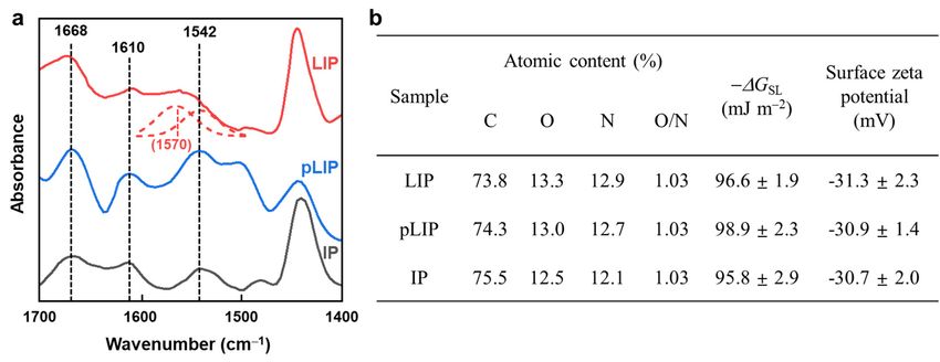
2.2. Membrane Preparation
The TFC membrane was prepared by depositing the PEI/PAA or PIPA interlayer on
a PAN support, followed by LIP (Figure 1). To fabricate the prototype PEI/PAA-interlay-
Membranes 2022, 12, 156 3 of 13
ered LIP membrane (Figure 1a), the PAN support was first hydrolyzed by soaking it into
a NaOH (1.5 M) aqueous solution at 45 °C for 120 min and subsequently washing it with
DI water. This hydrolysis step enhanced the surface hydrophilicity and negative charge
◦ C for 120 min and subsequently washing it with
of NaOH
the PAN (1.5support,
M) aqueousthussolution at 45the
facilitating deposition of the PEI/PAA interlayer. Cationic
DI water. This hydrolysis step enhanced the surface hydrophilicity and negative charge
PEI was electrostatically deposited on the hydrolyzed PAN (HPAN) support with an en-
of the PAN support, thus facilitating the deposition of the PEI/PAA interlayer. Cationic
hanced negative surface charge by immersing the support into a PEI (0.1 wt.%) aqueous
PEI was electrostatically deposited on the hydrolyzed PAN (HPAN) support with an
solution
enhancedcontaining
negative 0.5 M NaCl
surface charge(pH
by 10.6)
immersingfor 15themin, followed
support into aby
PEIthorough
(0.1 wt.%)rinsing
aqueous with
DIsolution
water. Subsequently,
containing 0.5 M the support
NaCl wasfor
(pH 10.6) immersed into an anionic
15 min, followed PAArinsing
by thorough (0.1 wt.%) aque-
with DI
ous solution containing 0.5 M NaCl (pH 3.5) for 10 min and rinsed
water. Subsequently, the support was immersed into an anionic PAA (0.1 wt.%) aqueouswith DI water, produc-
ingsolution
the PEI/PAA polyelectrolyte
containing 0.5 M NaCl interlayer.
(pH 3.5) forThis 10 mininterlayer
and rinsed blocked thewater,
with DI support pores and
producing
thus
theenabled
PEI/PAA thepolyelectrolyte
effective construction
interlayer.of an
This upper PA selective
interlayer blockedlayer via LIPpores
the support [19]. The
and PA
thus enabled
selective layer wasthe effective construction
fabricated of an upper
on the PEI/PAA PA selective
interlayer via LIPlayer via LIP
of MPD and[19].
TMC,Thefol-
PA selective layer was fabricated on the PEI/PAA interlayer via
lowing the protocol optimized in our previous report [19]. The PEI/PAA-interlayered LIP of MPD and TMC,
following
HPAN the protocol
support optimized
was dipped into aninMPD
our previous
(0.5 wt.%)report [19]. The
aqueous PEI/PAA-interlayered
solution for 3 min and then
HPAN support was dipped into an MPD (0.5 wt.%) aqueous
thoroughly rinsed with DI water. This rinsing step is a critical process solution for 3 min and Rinsing
in LIP. then
thoroughly rinsed with DI water. This rinsing step is a critical process in LIP. Rinsing
removes loosely bound MPD, which allows for the surface-confined, uniform and tight
removes loosely bound MPD, which allows for the surface-confined, uniform and tight
MPD deposition, unlike conventional IP, where excess MPD impregnated in support
MPD deposition, unlike conventional IP, where excess MPD impregnated in support pores
pores is irregularly
is irregularly removed
removed with awith
rollera or
roller
an airor knife.
an airTheknife. The support
support was thenwas theninto
soaked soaked
a
into a TMC (0.1 wt.%) solution in n-hexane for 1 min to induce the crosslinking
TMC (0.1 wt.%) solution in n-hexane for 1 min to induce the crosslinking reaction between reaction
between the pre-deposited
the pre-deposited MPD andMPD TMC,and TMC,a crosslinked,
forming forming a crosslinked,
fully aromatic fully aromaticlayer.
PA selective PA se-
lective
Afterlayer.
the LIP After the the
process, LIPmembrane
process, the wasmembrane
rinsed withwaspure rinsed withand
n-hexane pure at 70 ◦ Cand
n-hexane
dried
dried
for 2atmin.
70 °C for 2 min.
Figure
Figure 1. Schematic
1. Schematic illustrationof
illustration ofthe
themembrane
membrane fabrication
fabricationprocess.
process.(a)(a)
Polyelectrolyte (PEI/PAA)-
Polyelectrolyte (PEI/PAA)-
interlayered
interlayeredLIP
LIPand
and(b)
(b)poly(piperazineamide) (PIPA)-interlayered
poly(piperazineamide) (PIPA)-interlayered LIPLIP (pLIP)
(pLIP) membranes.
membranes.
ToTofabricate
fabricatethe
the pLIP
pLIP membrane
membrane(Figure 1b),1b),
(Figure thethe
HPAN
HPANsupport was dipped
support into a PIP
was dipped into a
(0.25–2.0 wt.%) aqueous solution for 3 min and then rinsed with DI water, followed by air
PIP (0.25–2.0 wt.%) aqueous solution for 3 min and then rinsed with DI water, followed
gun blowing. Subsequently, the support was placed in contact with a TMC (0.0–1 wt.%)
by air gun blowing. Subsequently, the support was placed in contact with a TMC (0.0–1
solution in n-hexane for 1 min, producing a PIPA interlayer. Next, the MPD/TMC-based
wt.%) solution layer
PA selective in n-hexane for 1 min,
was fabricated producing
on the a PIPA interlayer.
PIPA interlayer Next, the
via LIP following theMPD/TMC-
protocol
based PA selective
described layer various
above using was fabricated on the PIPA
MPD (0.05–5.0 wt.%)interlayer
and TMC via LIP following
(0.01–0.5 the pro-
wt.%) concen-
tocol
trations. It should be noted that the MPD adsorption time was fixed to 3 min becausecon-
described above using various MPD (0.05–5.0 wt.%) and TMC (0.01–0.5 wt.%)
centrations. It should
MPD adsorption for be
lessnoted
than 3that
minthe
ledMPD adsorption
to poor separationtime was fixedbytolowering
performance 3 min because
the
concentration of adsorbed MPD.
For comparison, an IP membrane was also fabricated via conventional IP following
the protocol optimized in our previous study [19]. The PAN support was impregnated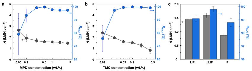
Membranes 2022, 12, 156                                                                                          4 of 13

                          with an MPD (0.5 wt.%) aqueous solution for 5 min, and then the excess MPD solution
                          was removed with an air knife. Subsequently, the support was brought into contact with a
                          TMC (0.1 wt.%) solution in n-hexane for 3 min, followed by rinsing with pure n-hexane
                          and drying a 70 ◦ C for 2 min.

                          2.3. Membrane Characterization
                                The surface morphologies of the membranes were examined using scanning electron
                          microscopy (SEM, Inspect F50, FEI, Hillsboro, OR, USA) and atomic force microscopy
                          (AFM, NX10, Park Systems, Suwon, Korea). The root-mean-square (rms) surface roughness
                          of the membranes was quantified from their AFM topographic images of 5 × 5 µm2 .
                          Cross-sectional micrographs of the membranes were obtained using transmission electron
                          microscopy (TEM, Titan TM 80-300, FEI, Hillsboro, OR, USA) at an accelerating voltage
                          of 300 kV. The TEM sample was prepared by curing the membrane coupon in EPON™
                          resin, followed by slicing it into a nanometer-scale thickness using an ultramicrotome
                          (Reichert Ultracut S, Leica, Wetzlar, Germany). Fourier transform infrared spectroscopy
                          (FT-IR) and X-ray photoelectron spectroscopy (XPS) were used to analyze the chemical
                          structures of the membranes. FT-IR was performed using a Spectrum Two spectrometer
                          (PerkinElmer, Waltham, MA, USA) with an attenuated total reflectance unit. XPS spectra
                          were collected on a PHI-5000 Versaprobe spectrometer (ULVAC-PHI, Chigasaki, Japan)
                          using monochromatized Al–Kα radiation at 1486.6 eV. The water contact angle on the
                          membrane surface was measured using a contact angle measurement system (Pheonix-300,
                          SEO Corporation, Suwon, South Korea), and then converted to the solid–liquid interfacial
                          free energy (−∆GSL ) to evaluate the intrinsic surface hydrophilicity of the membranes [23].
                          −∆GSL was calculated using the equation, −∆GSL = γL (1 + cosθ/r), where γL is the surface
                          tension of water, θ is the measured water contact angle, and r is the ratio of the actual
                          membrane surface area to the projected area determined using AFM [23]. The surface
                          charge properties of the membranes were characterized by measuring their surface zeta
                          potential at pH 5.8 using an electrophoretic measurement apparatus (ELS-2000Z, Otsuka
                          Electronics, Hirakata, Japan).

                          2.4. Membrane Performance and pH Stability
                                The water flux (Jw ) and NaCl rejection (RNaCl ) of the membranes were evaluated by
                          permeating a NaCl (2000 ppm) aqueous solution across an effective membrane area (am ) of
                          14.5 cm2 in a cross-flow system at a pressure (∆P) of 15.5 bar, a flow rate of 1 L min−1 , and
                          25 ◦ C. Performance data were collected after stabilization for 12 h. Jw (L m−2 h−1 , LMH)
                          was calculated from the volume of the permeate (∆V) collected for a certain time interval (t)
                          using the equation, Jw = ∆V/am t. Water permeance (A, LMH bar−1 ) was then quantified
                          using the equation, Jw /(∆P − ∆π), where ∆π is the transmembrane osmotic pressure differ-
                          ence [19]. RNaCl (%) was calculated using the following equation, RNaCl = 100 × (1 − Cp /Cf ),
                          where Cp and Cf are the NaCl concentrations of the permeate and feed, respectively [19].
                          The pH stability of the membranes was assessed by measuring their A and RNaCl using
                          feed solutions at different pH values, and the pH of each feed solution was adjusted using
                          NaOH and HCl.

                          3. Results and Discussion
                          3.1. Membrane Performance
                               An optimal interlayer should have a structure that can effectively construct the upper
                          PA selective layer while imparting minimal hydrodynamic resistance to the LIP-assembled
                          membrane. Hence, the PIPA interlayer was optimized by characterizing its surface structure
                          and RO performance as a function of PIP and TMC concentrations used for its formation
                          (Figures 2 and 3). At a fixed TMC concentration (0.1 wt.%), all the PIPA interlayers
                          prepared with various PIP concentrations (0.25–2.0 wt.%) completely blocked support
                          pores because no support pores were visible in SEM surface images (Figure 2a–d). Low
                          PIP concentrations (0.25–1.0 wt.%) led to the formation of a uniform and smooth surface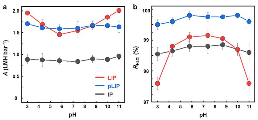
structure and RO performance as a function of PIP and TMC concentrations used for its
formation (Figures 2 and 3). At a fixed TMC concentration (0.1 wt.%), all the PIPA inter
layers prepared with various PIP concentrations (0.25–2.0 wt.%) completely blocked sup
Membranes 2022, 12, 156 port pores because no support pores were visible in SEM surface images (Figure 5 of 13 2a–d)
Low PIP concentrations (0.25–1.0 wt.%) led to the formation of a uniform and smooth
surface structure (Figure 2a–c), while the high PIP concentration (2.0 wt.%) produced
some nodular
structure (Figuresurface features
2a–c), while (Figure
the high 2d). Along with
PIP concentration the surface
(2.0 wt.%) producedmorphological
some nodular change
increasing
surface the PIP
features concentration
(Figure 2d). Alongprogressively
with the surfacereduced A whilechange,
morphological increasing RNaCl up to 1.0
increasing
wt.%,
the PIPabove which Rprogressively
concentration NaCl decreasedreduced
(FigureA2e). A higher
while PIP concentration
increasing RNaCl up to 1.0could
wt.%,increase
above which R
the crosslinking density and thickness of the PIPA layer by enhancing the ratethe
NaCl decreased (Figure 2e). A higher PIP concentration could increase and extent
crosslinking density and thickness
of the IP reaction [24–27], of thein
resulting PIPA layer by enhancing
a decrease the increase
in A, but an rate and extent of .the
in RNaCl However
IP reaction [24–27], resulting in a decrease in A, but an increase in RNaCl . However, excessive
excessive PIP concentrations (>1.0 wt.%) could induce the unbalanced stoichiometric re
PIP concentrations (>1.0 wt.%) could induce the unbalanced stoichiometric reaction of
action of PIP and TMC, yielding a looser, thicker, and irregular PIPA structure with
PIP and TMC, yielding a looser, thicker, and irregular PIPA structure with loosely packed
loosely packed
nodular nodular[25,28],
surface features surface features
which [25,28],for
can account which can account
the decline in both for theRdecline
A and in both
NaCl at
A and R NaCl
2.0 wt.% MPD. at 2.0 wt.% MPD.
Membranes 2022, 12, x FOR PEER REVIEW 6 of 1
higher A but relatively lower RNaCl (Figure 4a), presumably due to the formation of a loose
and thinner PA layer resulting from the lack of MPD monomers used for PA formation
[30]. High MPD concentrations (>0.5 wt.%) also resulted in unsatisfactory RO performance
(i.e., relatively low A and RNaCl). The excessive amount of MPD, which generated an im
proper MPD/TMC stoichiometry, could create a less crosslinked incipient PA layer, allow
Figure2.2.Surface
Figure Surfacemorphologies
morphologies andand
RO RO performance
performance of theof the interlayers
PIPA PIPA interlayers prepared
prepared with various
with various
ing MPD to continue to diffuse and react with TMC, consequently
PIP concentrations. (a–d) SEM surface images and (e) water permeance (A) and NaCl
producing a less perm
PIP concentrations. (a–d) SEM surface images and (e) water permeance (A) and NaCl rejection (R NaCl ) rejection
selective
(R
of NaCl)PIPA
the PA
of the layerinterlayers
PIPA
interlayers [6,29].
prepared Atat0.5
0.1 wt.%
prepared MPD,
wt.% at
TMC the
0.1 with
wt.% pLIPwith
TMC
different membrane
differentexhibited the(b)highest
PIP concentrations:
PIP concentrations: (a) 0.25, 0.5, (a) R NaC
0.25
and
(b)1.0,
(c) satisfactory
0.5,and
(c) (d)
1.0,2.0
and A, presumably
(d)PIP.
wt.% 2.0 wt.% PIP. due to the balanced MPD/TMC concentration.
At a fixed PIP concentration (0.5 wt.%), an exceedingly low TMC concentration (0.01
wt.%) produced a highly defective and irregular PIPA layer with remarkably high A bu
marginal RNaCl (Figure 3a,e) due to the significantly suppressed IP reaction. The PIPA layer
prepared with 0.1 wt.% TMC had a fairly smooth and uniform surface, exhibiting the
highest RNaCl and reasonably high A due to the optimized IP reaction (Figure 3b,e), indi-
cating its suitability as a proper interlayer. At high TMC concentrations exceeding 0.1
wt.%, both A and RNaCl of the PIPA layer decreased, and nodules were prominent on its
surface (Figure 3c–e). This undesirable performance and surface structure of the PIPA
layer could be attributed to the imbalanced stoichiometry of the PIP and TMC monomers
that participated in the IP reaction, as mentioned above [22,29]. Based on these results, the
optimal PIP and TMC concentrations were determined to be 0.5 and 0.1 wt.%, respec-
tively, which produced a smooth, uniform, and defect-free PIPA layer with good perm-
selectivity.
Following the optimization of the PIPA interlayer, the RO performance of the LIP-
assembled PA selective layer was optimized by varying MPD and TMC concentrations
(Figure
Figure3.3.4).
Figure Likemorphologies
Surface
Surface the PIPA interlayer,
morphologies andand ROthe balanced
performance
RO performance stoichiometry
of theof theinterlayers
PIPA of MPD
PIPA interlayers andvarious
prepared
prepared with TMC resulted
with variou
TMC
in
TMC concentrations.
theconcentrations.
optimal performance(a–d)
(a–d) SEMSEM surface
of the
surface images
fabricated
images and
pLIP
and (e) (e) water
membrane
water permeance
permeance (A) and (A)
(Figure and
4a,b).
NaCl NaCl rejection
Specifically,
rejection at
(R
(R ) of
of the
the PIPA
PIPA interlayers
interlayers prepared
prepared at at
0.5 0.5
wt.% wt.%
PIP PIP
with with different
different TMC TMC concentrations:
concentrations:
a fixed TMC concentration (0.1 wt.%), low MPD concentrations (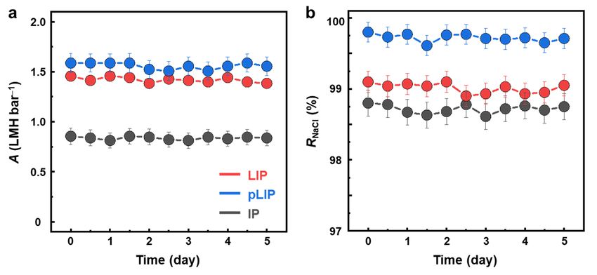
(i.e., relatively low A and RNaCl). The excessive amount of MPD, which generated an im-
proper MPD/TMC stoichiometry, could create a less crosslinked incipient PA layer, allow-
ing MPD to continue to diffuse and react with TMC, consequently producing a less perm-
selective PA layer [6,29]. At 0.5 wt.% MPD, the pLIP membrane exhibited the highest RNaCl
and satisfactory A, presumably due to the balanced MPD/TMC concentration.
Membranes 2022, 12, 156 6 of 13
At a fixed PIP concentration (0.5 wt.%), an exceedingly low TMC concentration
(0.01 wt.%) produced a highly defective and irregular PIPA layer with remarkably high A
but marginal RNaCl (Figure 3a,e) due to the significantly suppressed IP reaction. The PIPA
layer prepared with 0.1 wt.% TMC had a fairly smooth and uniform surface, exhibiting
the highest RNaCl and reasonably high A due to the optimized IP reaction (Figure 3b,e),
indicating its suitability as a proper interlayer. At high TMC concentrations exceeding
0.1 wt.%, both A and RNaCl of the PIPA layer decreased, and nodules were prominent on
its surface (Figure 3c–e). This undesirable performance and surface structure of the PIPA
layer could be attributed to the imbalanced stoichiometry of the PIP and TMC monomers
that participated in the IP reaction, as mentioned above [22,29]. Based on these results, the
optimal PIP and TMC concentrations were determined to be 0.5 and 0.1 wt.%, respectively,
which produced a smooth, uniform, and defect-free PIPA layer with good permselectivity.
Following the optimization of the PIPA interlayer, the RO performance of the LIP-
assembled PA selective layer was optimized by varying MPD and TMC concentrations
Figure
(Figure 3. 4).
Surface
Like morphologies and ROthe
the PIPA interlayer, performance of the PIPA interlayers
balanced stoichiometry of MPDprepared
and TMC with various
resulted
TMC concentrations. (a–d) SEM surface images and (e) water permeance (A)
in the optimal performance of the fabricated pLIP membrane (Figure 4a,b). Specifically, atand NaCl rejection
(R
a NaCl
fixed) ofTMC
the PIPA interlayers prepared
concentration at low
(0.1 wt.%), 0.5 wt.%
MPDPIP with different (0.5
concentrations concentration
wt.%) also (0.5 wt.%),inA unsatisfactory
resulted decreased continu-
RO
ously with an (i.e.,
performance increase in TMC
relatively lowconcentration,
A and RNaCl ). while RNaCl initially
The excessive amount increased
of MPD,and thengen-
which plat-
eaued (Figure 4b). Higher TMC concentrations constructed a denser
erated an improper MPD/TMC stoichiometry, could create a less crosslinked incipient PA and thicker PA layer
by facilitating
layer, allowingthe MPDLIPtoreaction
continue between MPD
to diffuse andand
reactTMCwith[30],
TMC,thus yielding a more
consequently selective
producing a
but
lessless permeablePA
permselective membrane. The
layer [6,29]. At optimal
0.5 wt.% MPD
MPD,and TMCmembrane
the pLIP concentrations thatthe
exhibited achieved
high-
the RNaClRO
est best andperformance A, presumably
satisfactory were 0.5 and 0.1due to the
wt.%, balanced MPD/TMC concentration.
respectively.
Figure
Figure 4.4. Performance
Performance optimization
optimization and
and comparison
comparison of of the
the PIPA-interlayered
PIPA-interlayeredLIP
LIP(pLIP)
(pLIP)mem-
mem-
branes. (a, b) Water permeance (A) and NaCl rejection (R NaCl ) of the pLIP membranes prepared
branes. (a,b) Water permeance (A) and NaCl rejection (RNaCl ) of the pLIP membranes prepared with
(a) different MPD concentrations at 0.1 wt.% TMC and (b) different TMC concentrations
with (a) different MPD concentrations at 0.1 wt.% TMC and (b) different TMC concentrations atat 0.5 wt.%
MPD. (c) The RO performance of the optimized LIP, pLIP, and conventional IP membranes.
0.5 wt.% MPD. (c) The RO performance of the optimized LIP, pLIP, and conventional IP membranes.
The ROother
On the performance
hand, at aoffixed
the MPD
optimized pLIP membrane
concentration (0.5 wt.%),was compared
A decreased with that of
continuously
the control
with LIP and
an increase IP membranes
in TMC (Figure
concentration, 4c).
while Theinitially
RNaCl conventional IP membrane
increased exhibited
and then plateaued
(Figure 4b). Higher TMC concentrations constructed a denser and thicker PA layer by
facilitating the LIP reaction between MPD and TMC [30], thus yielding a more selective but
less permeable membrane. The optimal MPD and TMC concentrations that achieved the
best RO performance were 0.5 and 0.1 wt.%, respectively.
The RO performance of the optimized pLIP membrane was compared with that of the
control LIP and IP membranes (Figure 4c). The conventional IP membrane exhibited poor
RO performance with low values of RNaCl (98.8 ± 0.3%) and A (0.86 ± 0.08 LMH bar−1 ).
A conventional IP process is known to be inadequate for fabricating a highly permselec-
tive PA layer on a hydrophilic support such as PAN because the MPD solution forms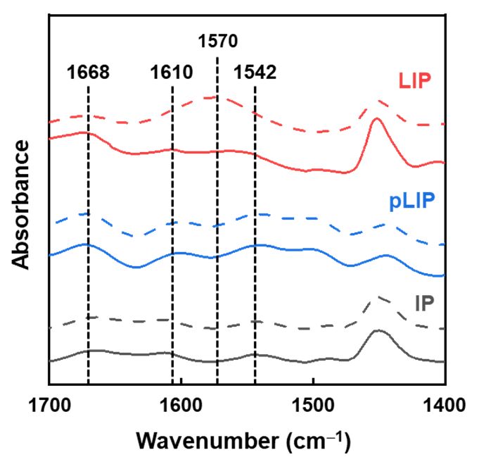
Membranes 2022, 12, 156                                                                                              7 of 13

                          a concave meniscus in the support pores and MPD diffusion is hindered by the sup-
                          port [26,31,32]. Both the LIP and pLIP membranes exhibited higher RO performance
                          (i.e., higher RNaCl and A) than the IP membrane, demonstrating that the LIP method is
                          effective in fabricating a high-performance PA layer on a hydrophilic support. This is
                          presumably because the LIP method can induce uniform and dense monomer deposition
                          and generate a highly surface-confined reaction, enabled by the pre-deposition of the inter-
                          layer [19,26]. From a practical perspective, the LIP technique can broaden the application
                          spectrum of PA TFC membranes to osmosis-driven separation (e.g., forward osmosis) and
                          organic solvent filtration by fabricating hydrophilic support-based, high-performance mem-
                          branes [33,34]. Importantly, the pLIP membrane (99.8 ± 0.2%, 1.59 ± 0.09 LMH bar−1 ) had
                          higher RNaCl and A values than the LIP membrane (99.1 ± 0.2%, 1.46 ± 0.04 LMH bar−1 ),
                          meeting the RNaCl level required for a commercial RO process (>99.5%). The superior
                          performance of the pLIP membrane can be attributed to the advantageous attributes of the
                          PIPA interlayer over PEI/PAA. Unlike the electrostatically assembled PEI/PAA interlayer
                          that can absorb a certain amount of MPD, the tight molecular structure of the chemically
                          crosslinked PIPA interlayer can effectively limit MPD deposition to its surface. As a result,
                          the IP reaction could be more concentrated and confined to the interlayer surface of the pLIP
                          membrane, inducing a more localized and denser interfacial reaction. Furthermore, the
                          higher molecular density of the PIPA interlayer, as evidenced by its higher NaCl rejection
                          than the PEI/PAA interlayer [19], possibly enriched surface carboxyl and amide groups,
                          which would increase the number of deposited MPD monomers that would subsequently
                          react with TMC, consequently forming a denser and more permselective PA layer. In
                          particular, when compared with commercial and other reported lab-made RO membranes,
                          the pLIP membrane exhibited moderate A but higher RNaCl values (Table 1), highlighting
                          its excellent and competitive RO performance.

                          Table 1. Performance comparison of the membranes. Water permeance (A) and NaCl rejection (RNaCl )
                          of commercial and other reported lab-made RO membranes. The reported performance of lab-made
                          membranes was measured under same operating conditions (feed concentration = 2000 ppm NaCl,
                          operating pressure = 15.5 bar).

                                    Membrane               A (LMH bar−1 )        RNaCl (%)              Reference
                                             SW30LE          1.11 ± 0.11         98.8 ± 0.1
                                             SW30HR          1.03 ± 0.41         97.6 ± 1.1
                            Commercial        SWC4+          1.44 ± 0.23         99.6 ± 0.5             This study
                                               BW30          2.93 ± 0.21         98.4 ± 0.3
                                             BW30LE          3.76 ± 0.63         97.3 ± 0.5
                                                             1.56 ± 0.24         98.7 ± 0.5                [19]
                                                             1.60 ± 0.10         99.6 ± 0.3                [35]
                                                             1.85 ± 0.08         99.3 ± 0.2                [36]
                                                                 3.74               98.3                   [37]
                                    Lab-made
                                                             1.43 ± 0.08         99.0 ± 0.3                [38]
                                                                 2.74               98.2                   [39]
                                                             1.96 ± 0.14         99.5 ± 0.1                [40]
                                                             1.59 ± 0.09         99.8 ± 0.2         This study (pLIP)

                               To evaluate the structural robustness of the fabricated membranes, we monitored
                          their RO performance for 5 days (Figure 5). The RO performance of all the membranes
                          remained nearly unchanged during the long-term period of operation, confirming their
                          good structural stability.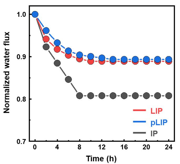
Membranes 2022, 12, x FOR PEER REVIEW
Membranes 2022, 12, 156 8 of 13
Figure5.5.Long-term
Figure Long-term operational stability
operational of the fabricated
stability membranes.membranes.
of the fabricated (a) Water permeance (A) and
(a) Water permeance
(b) NaCl rejection (RNaCl ) of the optimized LIP, pLIP, and conventional IP membranes for 5 days of
(b) NaCl rejection (RNaCl) of the optimized LIP, pLIP, and conventional IP membranes for 5
RO operation.
RO operation.
3.2. Membrane Structure and Properties
3.2. Membrane
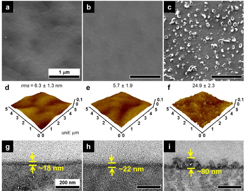
The surface and Structure and Properties
cross-sectional morphologies of the optimized pLIP membrane were
compared with those of the control LIP and IP membranes (Figure 6). The conventional
The surface and cross-sectional morphologies of the optimized pLIP membra
IP membrane had a relatively thick (~80 nm) and rough (rms = ~25 nm) structure with
compared
typical ridgewith those of
and nodular the control
surface LIP and
features (Figure IP membranes
6c,f,i). In a typical IP(Figure
process, 6). The conve
excess
IP membrane
MPD had a relatively
monomers impregnated in support thickpores(~80 nm) and
vigorously andrough (rms diffuse
continuously = ~25 to nm)the structu
organic
typicalphaseridge andandprovoke a disordered
nodular surface and rapid crosslinking
features (Figure reaction
6c,f,i). with
In aTMC [9,41,42],
typical IP process
constructing an inherently heterogeneous and rough
MPD monomers impregnated in support pores vigorously and continuously PA layer. Interestingly, both the LIP di
and pLIP membranes exhibited a much thinner (~20 nm), smoother (rms = ~6 nm), and more
the organic
uniform selectivephase
layer and provoke
structure than the a conventional
disorderedIPand rapid crosslinking
membrane. For the LIP andreaction
pLIP wi
[9,41,42], constructing
membranes, the presence of an aninterlayer
inherently couldheterogeneous
greatly confine theand rough PAreaction
polymerization layer. Intere
bothnear
zone the LIP and pLIP
the interlayer membranes
surface by blocking exhibited
supportapores
much andthinner (~20 nm),
thus allowing for MPDsmoother (
deposition
nm), and more uniform selective layer structure than the conventional step
on the interlayer surface [19,20,38,43]. Furthermore, the DI water rinsing IP membra
after MPD deposition could remove loosely bound MPD monomers, which enables minimal
the LIP and pLIP membranes, the presence of an interlayer could greatly con
but uniform and dense MPD deposition, consequently creating an ultrathin and smooth
polymerization
PA reaction
layer after the reaction withzone
TMC near the interlayer
[19,20,38,43]. Despite itssurface
smoother bysurface
blockingwith asupport
less po
thus allowing
effective for MPD
contact area compareddeposition
with the IPon the interlayer
membrane, the thinnersurface [19,20,38,43].
selective layer structure Furtherm
of the LIP-assembled membrane could primarily contribute
DI water rinsing step after MPD deposition could remove loosely bound MPD mon to its higher A by significantly
reducing hydrodynamic resistance [44]. Together with excellent RO performance, the
which enables minimal but uniform and dense MPD deposition, consequently cre
highly smooth surface of the LIP-assembled membrane would be beneficial for mitigating
ultrathin
fouling and smooth
by reducing PA layer
the surface area forafter
foulanttheattachment
reaction and with TMC [19,20,38,43].
accumulation [45]. To Des
smoother surface
demonstrate this, wewith a lessthe
monitored effective
water flux contact
of the area compared
fabricated membraneswithupon the IP themembr
thinnerofselective
addition layer structure
a model organic foulant (bovineof the LIP-assembled
serum albumin, BSA, membrane
100 ppm) to the could
DI waterprimarily
feed for 24 h of RO operation (Figure 7). Both the LIP and pLIP
ute to its higher A by significantly reducing hydrodynamic resistance [44]. Togeth membranes led to a low
flux decline than the conventional IP membrane, confirming their better fouling resistance.
excellent RO performance, the highly smooth surface of the LIP-assembled me
Figure 8 displays the physicochemical properties of the fabricated membranes. All the
would be beneficial
membranes showed the for mitigating
characteristic FT-IRfouling
peaks by reducing the surface
of MPD/TMC-based areacm
PA at 1668 for
−1 foulant
mentbond
(C=O andstretching),
accumulation 1542 cm −1 (N–H
[45]. To demonstrate this, weand
bond in-plane bending), 1610 cm−1the
monitored water flux of
(H-bonded
C=O
ricatedbond stretching) (Figure
membranes upon 8a) the[23,40],
addition indicating the formation
of a model organicoffoulant
a fully aromatic
(bovinePAserum a
layer via IP or LIP. XPS analysis also revealed that the membranes had a nearly identical
BSA, 100 ppm) to the DI water feed for 24 h of RO operation (Figure 7). Both the
O/N ratio (~1.03), regardless of their fabrication methods (Figure 8b), confirming their
pLIP membranes
similar led to a at
chemical composition low theflux decline
surface. than thethere
Furthermore, conventional IP membrane,
was no significant differ- con
theirinbetter
ence fouling
the surface resistance.
hydrophilicity (−∆GSL ) and charge between the membranes (Figure 8b).
These results suggested that the excellent membrane performance of the LIP membrane
was mainly due to its thin and dense structure rather than its physicochemical properties.Membranes 2022, 12, x FOR PEER REVIEW 9 of 14
Membranes 2022,12,
Membranes2022, 12,156
x FOR PEER REVIEW 99of
of13
14
Figure6.
Figure
Figure 6.Morphologies
6. Morphologies of
Morphologies of the
ofthe fabricated
thefabricated
fabricatedmembranes.
membranes.
membranes. (a–c) SEM
(a–c)
(a–c) SEM
SEM surface, (d–f)
surface,
surface, AFM
(d–f)
(d–f) AFM AFM surface (with
surface
surface (with(with
rms
rms surface roughness), and (g–i) TEM cross-sectional images of the (a,d,g) LIP, (b,e,h) pLIP, and
rms surface roughness),and
surface roughness), and(g–i)
(g–i)TEM
TEMcross-sectional
cross-sectional images
images of of
thethe (a,d,g)
(a,d,g) LIP,LIP, (b,e,h)
(b,e,h) pLIP,
pLIP, and and
(c,f,i)conventional
(c,f,i) conventional IP membranes.
IPmembranes.
membranes.
(c,f,i) conventional IP
Figure 7. Water flux normalized by the initial value of the LIP, pLIP, and conventional IP10mem-
Membranes 2022, 12, x FOR PEER REVIEW of 14
Figure 7.
branes7. Water
upon flux
theflux
Water normalized
addition of BSA
normalized by
thethe
bytothe DI initial
water
initial value
valuefeed forof
of the 24the
LIP,of LIP,and
RO
pLIP, pLIP, and conventional
operation.
conventional IP mem-
IP membranes
branes upon
upon the the addition
addition of BSA toofthe
BSADIto the DI
water feed water
for 24feed foroperation.
of RO 24 of RO operation.
Figure 8 displays the physicochemical properties of the fabricated membranes. All
the membranes showedthe
Figure 8 displays thephysicochemical
characteristic FT-IR peaks ofofMPD/TMC-based
properties PA at 1668 All
the fabricated membranes.
cm −1 (C=O bond stretching), 1542 cm−1 (N–H bond in-plane bending), and 1,610 cm−1 (H-
the membranes showed the characteristic FT-IR peaks of MPD/TMC-based PA at 1668
bonded
cm −1 (C=OC=O bond
bond stretching)1542
stretching), (Figure
cm−18a) [23,40],
(N–H indicating
bond in-planethe formation
bending), of 1,610
and a fullycm
aro-
−1 (H-
matic PA
bonded layer
C=O via IP
bond or LIP. XPS
stretching) analysis
(Figure 8a)also revealed
[23,40], that thethe
indicating membranes
formationhadof aa nearly
fully aro-
identical O/N ratio (~1.03), regardless of their fabrication methods (Figure 8b),
matic PA layer via IP or LIP. XPS analysis also revealed that the membranes had a nearlyconfirming
their similar
identical O/Nchemical composition
ratio (~1.03), at the
regardless surface.
of their Furthermore,
fabrication methodsthere was no
(Figure significant
8b), confirming
difference in the surface hydrophilicity (−ΔG SL) and charge between the membranes (Fig-
their similar chemical composition at the surface. Furthermore, there was no significant
ure 8b). These results suggested that the excellent membrane performance of the LIP
difference in the surface hydrophilicity (−ΔGSL) and charge between the membranes (Fig-
membrane was mainly due to its thin and dense structure rather than its physicochemical
ure 8b). These results suggested that the excellent membrane performance of the LIP
properties.
membrane was mainly due to its thin and dense structure rather than its physicochemical
properties.
Figure8.8. Physicochemical
Figure Physicochemical properties of the fabricated membranes.
membranes. (a)(a) FT-IR
FT-IR spectra
spectra and
and (b)
(b) XPS
XPS
atomic
atomiccontent,
content, intrinsic
intrinsic surface
surface hydrophilicity −∆GSLSL),),and
hydrophilicity ((−ΔG andsurface
surfacezeta
zetapotential
potentialofofthe
theLIP,
LIP,pLIP,
pLIP,
andconventional
and conventional IPIP membranes.
membranes.
3.3. Membrane pH Stability
The pH stability of the membrane is an important consideration for its practical ap-
plication, as the membrane is exposed to various pH conditions during cleaning and pre-Membranes 2022, 12, 156 10 of 13
3.3. Membrane pH Stability
The pH stability of the membrane is an important consideration for its practical
application, as the membrane is exposed to various pH conditions during cleaning and
pre-treatment processes [46,47]. The prototype polyelectrolyte-interlayered LIP mem-
brane lacks pH stability, possibly due to the weak polyelectrolyte nature of its PEI/PAA
interlayer [19,48]. To demonstrate the enhanced pH stability of the newly developed pLIP
membrane, its RO performance was monitored by varying the feed pH, and the results
were compared with those of the control LIP and IP membranes (Figure 9). Unlike the
conventional IP membrane exhibiting stable RO performance, regardless of the feed pH,
the LIP membrane showed a noticeable reduction in RNaCl with an increase in A under both
acidic (pH < 6) and basic (pH > 8) conditions. This result indicated that the LIP membrane
became defective under acidic and basic conditions, presumably due to the structural
change in the PEI/PAA interlayer responding to pH conditions [49,50]. Specifically, since
PEI tends to be protonated under acidic conditions, electrostatic repulsion between the
PEI chains would be reinforced, inducing reorganization of polymer conformation [51].
Similarly, at higher pH, PAA becomes more anionic due to enhanced deprotonation, which
would lead to significant electrostatic deformation of PAA [52]. As a result, the PEI/PAA
interlayer could be more prone to structural disintegration when it was exposed to acidic
or basic conditions, causing damage to the overlaid PA selective layer, which rendered
the membrane less selective and more permeable. In contrast, the RO performance of
the pLIP membrane remained intact over the entire pH range (3–11), demonstrating its
superior pH stability to the polyelectrolyte-interlayered LIP membrane. The excellent pH
stability of the pLIP membrane is likely due to its chemically crosslinked and pH-durable
PIPA interlayer [24], which can ensure its stable operation under various pH conditions.
Although most TFC RO membranes fabricated via conventional IP also perform stably
Membranes 2022, 12, x FOR PEER REVIEW 11
in the pH range from 3 to 11, the pLIP membrane exhibited greater NaCl rejection and
antifouling performance.
Figure 9.9.pH
Figure pHstability forfor
stability the the
fabricated membranes.
fabricated (a) Water
membranes. (a)permeance (A) and (b)(A)
Water permeance NaCl rejection
and (b) NaCl rejec
(RNaCl
(RNaCl)) of
of the
theLIP,
LIP,pLIP, andand
pLIP, conventional IP membranes
conventional as a function
IP membranes of the feedof
as a function pH.
the feed pH.
Our claim was further confirmed by the change in the FT-IR spectra of the fabri-
catedOur claim was
membranes afterfurther
exposureconfirmed by the
to the acidic (pHchange in the
3) solution for FT-IR spectraby
2 h, followed ofthe
the fabric
membranes
exposure to theafter exposure
basic to the
solution for 2 h, acidic (pH
as shown in 3) solution
Figure for the
10. Both 2 h,pLIP
followed by the expo
and conven-
to theIPbasic
tional solution
membranes for 2 h,the
exhibited asunchanged
shown inFT-IR
Figure 10. Both
spectra, even the
afterpLIP and toconventiona
exposure the
acidic/basic condition,
membranes exhibitedwhich was consistent
the unchanged withspectra,
FT-IR their excellent pH stability.
even after exposure In contrast,
to the acidic/b
the polyelectrolyte-interlayered
condition, which−was consistent LIP membrane
with theirshowed the pronounced
excellent pH stability.peak 1570 cm−the
Inatcontrast,
1
polye
(asymmetric COO stretching), characteristic of the HPAN support [19], after exposure
trolyte-interlayered LIP membrane showed the pronounced peak at 1,570 cm (asymm −1
to the acidic/basic condition, which can be attributed to the destruction of the interlayer
ric COOfrom
resulting
− stretching), characteristic of the HPAN support [19], after exposure to
its poor pH stability.
acidic/basic condition, which can be attributed to the destruction of the interlayer res
ing from its poor pH stability.condition, which was consistent with their excellent pH stability. In contrast, th
trolyte-interlayered LIP membrane showed the pronounced peak at 1,570 cm−1
ric COO− stretching), characteristic of the HPAN support [19], after expos
Membranes 2022, 12, 156
acidic/basic condition, which can be attributed to the destruction of11 the
of 13
interla
ing from its poor pH stability.
Figure 10. FT-IR spectra of the LIP, pLIP, and conventional IP membranes before (solid line) and after
Figure 10. FT-IR spectra of the LIP, pLIP, and conventional IP membranes before (sol
(dashed line) exposure to the acidic (2 h)/basic (2 h) condition.
after (dashed line) exposure to the acidic (2 h)/basic (2 h) condition.
4. Conclusions
In this study, a PA TFC membrane was prepared via LIP, where a PIP/TMC-based
4. Conclusions
PIPA interlayer was introduced to improve the RO performance and pH stability of the
In this
prototype study, a (PEI/PAA)-interlayered
polyelectrolyte PA TFC membraneLIP was prepared
membrane. viatoLIP,
Similar where
the control LIPa PIP/T
membrane,
PIPA the PIPA-interlayered
interlayer was introduced LIP (pLIP) membrane
to improve theexhibited a much smoother
RO performance and and
pH stab
thinner selective layer structure than the conventional IP-assembled membrane by enabling
prototype polyelectrolyte (PEI/PAA)-interlayered LIP membrane. Similar to t
confined, uniform, and dense MPD deposition and interfacial reaction. Although both the
LIP
pLIPmembrane,
and control LIPthe PIPA-interlayered
membranes showed higherLIP RO (pLIP) membrane
performance than the IPexhibited
membrane,a much
and thinner
the pLIP selective
membrane layer structure
outperformed than theand
the LIP membrane conventional
commercial ROIP-assembled
membranes. mem
The improved performance was related to the PIPA interlayer, which enabled
enabling confined, uniform, and dense MPD deposition and interfacial reaction denser MPD
deposition and a more confined reaction than the PEI/PAA interlayer. Importantly, the
both the pLIP and control LIP membranes showed higher RO performance t
chemically crosslinked and pH-stable nature of the PIPA interlayer resulted in the superior
membrane,
pH stability of the pLIP
the pLIP membrane
membrane outperformed
compared the LIP membrane
to the PEI/PAA-interlayered and comm
LIP membrane.
membranes. The improved
The proposed strategy can widen theperformance wasofrelated
application range to the PIPA
TFC membranes interlayer, w
by achieving
their high separation performance and pH durability using hydrophilic supports.
bled denser MPD deposition and a more confined reaction than the PEI/PAA
Importantly, the chemically
Author Contributions: crosslinked
Conceptualization, and pH-stable
J.-H.L.; methodology, M.-G.S. and nature of analysis,
W.C.; formal the PIPA int
M.-G.S. and W.C.; investigation, M.-G.S. and W.C.; data curation, M.-G.S.; writing—original draft
preparation, M.-G.S. and W.C.; writing—review and editing, J.-H.L.; visualization, M.-G.S. and W.C.;
supervision, J.-H.L.; project administration, J.-H.L.; funding acquisition, W.C. and J.-H.L. All authors
have read and agreed to the published version of the manuscript.
Funding: This research was supported by the National Research Foundation of Korea (NRF) grant
funded by the Korean government (2019R1A2C1002333 and 2020R1I1A1A01064474) and the Technology
Innovation Program (20010914) funded by the Ministry of Trade, Industry & Energy (MOTIE, Korea).
Institutional Review Board Statement: Not applicable.
Informed Consent Statement: Not applicable.
Data Availability Statement: The authors declare that all data supporting the findings of this study
are available within the article.
Conflicts of Interest: The authors declare no conflict of interest. The funders had no role in the design
of the study; in the collection, analyses, or interpretation of data; in the writing of the manuscript, or
in the decision to publish the results.Membranes 2022, 12, 156 12 of 13
References
1. Elimelech, M.; Phillip, W.A. The future of seawater desalination: Energy, technology, and the environment. Science 2011, 333,
712–717. [CrossRef] [PubMed]
2. Park, K.; Kim, J.; Yang, D.R.; Hong, S. Towards a low-energy seawater reverse osmosis desalination plant: A review and theoretical
analysis for future directions. J. Membr. Sci. 2020, 595, 117607. [CrossRef]
3. Giwa, A.; Akther, N.; Dufour, V.; Hasan, S.W. A critical review on recent polymeric and nano-enhanced membranes for reverse
osmosis. RSC Adv. 2016, 6, 8134–8163. [CrossRef]
4. Li, D.; Yan, Y.S.; Wang, H.T. Recent advances in polymer and polymer composite membranes for reverse and forward osmosis
processes. Prog. Polym. Sci. 2016, 61, 104–155. [CrossRef]
5. Shannon, M.A.; Bohn, P.W.; Elimelech, M.; Georgiadis, J.G.; Marinas, B.J.; Mayes, A.M. Science and technology for water
purification in the coming decades. Nature 2008, 452, 301–310. [CrossRef]
6. Xu, J.; Yan, H.; Zhang, Y.; Pan, G.Y.; Liu, Y.Q. The morphology of fully-aromatic polyamide separation layer and its relationship
with separation performance of TFC membranes. J. Membr. Sci. 2017, 541, 174–188. [CrossRef]
7. Warsinger, D.M.; Chakraborty, S.; Tow, E.W.; Plumlee, M.H.; Bellona, C.; Loutatidou, S.; Karimi, L.; Mikelonis, A.M.; Achilli, A.;
Ghassemi, A.; et al. A review of polymeric membranes and processes for potable water reuse. Prog. Polym. Sci. 2016, 81, 209–237.
[CrossRef]
8. Shang, C.; Pranantyo, D.; Zhang, S. Understanding the roughness-fouling relationship in reverse osmosis: Mechanism and
implications. Environ. Sci. Technol. 2020, 54, 5288–5296. [CrossRef]
9. Gu, J.E.; Lee, S.; Stafford, C.M.; Lee, J.S.; Choi, W.; Kim, B.Y.; Baek, K.Y.; Chan, E.P.; Chung, J.Y.; Bang, J.; et al. Molecular
layer-by-layer assembled thin-film composite membranes for water desalination. Adv. Mater. 2013, 25, 4778–4782. [CrossRef]
10. Werber, J.R.; Osuji, C.O.; Elimelech, M. Materials for next-generation desalination and water purification membranes. Nat. Rev.
Mater. 2016, 1, 16018. [CrossRef]
11. Choi, W.; Gu, J.E.; Park, S.H.; Kim, S.; Bang, J.; Baek, K.Y.; Park, B.; Lee, J.S.; Chan, E.P.; Lee, J.H. Tailor-made polyamide
membranes for water desalination. ACS Nano 2015, 9, 345–355. [CrossRef] [PubMed]
12. Park, S.J.; Choi, W.; Nam, S.E.; Hong, S.; Lee, J.S.; Lee, J.H. Fabrication of polyamide thin film composite reverse osmosis
membranes via support-free interfacial polymerization. J. Membr. Sci. 2017, 526, 52–59. [CrossRef]
13. Jiang, S.; Cao, Z. Ultralow-fouling, functionalizable, and hydrolyzable zwitterionic materials and their derivatives for biological
applications. Adv. Mater. 2010, 22, 920–932. [CrossRef] [PubMed]
14. Yang, S.M.; Wang, J.Q.; Fang, L.F.; Lin, H.B.; Liu, F.; Tang, C.Y.Y. Electrosprayed polyamide nanofiltration membrane with
intercalated structure for controllable structure manipulation and enhanced separation performance. J. Membr. Sci. 2020, 602,
117971. [CrossRef]
15. Chowdhury, M.R.; Steffes, J.; Huey, B.D.; McCutcheon, J.R. 3D printed polyamide membranes for desalination. Science 2018, 361,
682–685. [CrossRef]
16. Park, S.J.; Ahn, W.G.; Choi, W.; Park, S.H.; Lee, J.S.; Jung, H.W.; Lee, J.H. A facile and scalable fabrication method for thin film
composite reverse osmosis membranes: Dual-layer slot coating. J. Mater. Chem. A 2017, 5, 6648–6655. [CrossRef]
17. Park, S.J.; Lee, J.H. Fabrication of high-performance reverse osmosis membranes via dual-layer slot coating with tailoring
interfacial adhesion. J. Membr. Sci. 2020, 614, 118449. [CrossRef]
18. Jiang, Z.; Karan, S.; Livingston, A.G. Water transport through ultrathin polyamide nanofilms used for reverse osmosis. Adv.
Mater. 2018, 30, 1705973. [CrossRef]
19. Choi, W.; Jeon, S.; Kwon, S.J.; Park, H.; Park, Y.I.; Nam, S.E.; Lee, P.S.; Lee, J.S.; Choi, J.; Hong, S.; et al. Thin film composite reverse
osmosis membranes prepared via layered interfacial polymerization. J. Membr. Sci. 2017, 527, 121–128. [CrossRef]
20. Choi, W.; Lee, C.; Lee, D.; Won, Y.J.; Lee, G.W.; Shin, M.G.; Chun, B.; Kim, T.S.; Park, H.D.; Jung, H.W.; et al. Sharkskin- mimetic
desalination membranes with ultralow biofouling. J. Mater. Chem. A 2018, 6, 23034–23045. [CrossRef]
21. Gohil, J.M.; Ray, P. A review on semi-aromatic polyamide TFC membranes prepared by interfacial polymerization: Potential for
water treatment and desalination. Sep. Purif. Technol. 2017, 181, 159–182. [CrossRef]
22. Liu, Y.L.; Zhao, Y.Y.; Wang, X.M.; Wen, X.H.; Huang, X.; Xie, Y.F.F. Effect of varying piperazine concentration and post-modification
on prepared nanofiltration membranes in selectively rejecting organic micropollutants and salts. J. Membr. Sci. 2019, 582, 274–283.
[CrossRef]
23. Shin, M.G.; Seo, J.Y.; Park, H.; Park, Y.I.; Ji, S.; Lee, S.S.; Lee, J.H. Positively charged membranes with fine-tuned nanopores for
ultrafast and high-precision cation separation. J. Mater. Chem. A 2021, 9, 24355–24364. [CrossRef]
24. Dalwani, M.; Benes, N.E.; Bargeman, G.; Stamatialis, D.; Wessling, M. Effect of pH on the performance of polyamide/polyacrylonitrile
based thin film composite membranes. J. Membr. Sci. 2011, 372, 228–238. [CrossRef]
25. Huang, S.H.; Hsu, C.J.; Liaw, D.J.; Hu, C.C.; Lee, K.R.; Lai, J.Y. Effect of chemical structures of amines on physicochemical
properties of active layers and dehydration of isopropanol through interfacially polymerized thin-film composite membranes. J.
Membr. Sci. 2008, 307, 73–81. [CrossRef]
26. Klaysom, C.; Hermans, S.; Gahlaut, A.; Van Craenenbroeck, S.; Vankelecom, I.F.J. Polyamide/Polyacrylonitrile (PA/PAN) thin
film composite osmosis membranes: Film optimization, characterization and performance evaluation. J. Membr. Sci. 2013, 445,
25–33. [CrossRef]Membranes 2022, 12, 156 13 of 13
27. Chai, G.Y.; Krantz, W.B. Formation and characterization of polyamide membranes via interfacial polymerization. J. Membr. Sci.
1994, 93, 175–192. [CrossRef]
28. An, Q.F.; Li, F.; Ji, Y.L.; Chen, H.L. Influence of polyvinyl alcohol on the surface morphology, separation and anti-fouling
performance of the composite polyamide nanofiltration membranes. J. Membr. Sci. 2011, 367, 158–165. [CrossRef]
29. Wei, J.; Liu, X.; Qiu, C.Q.; Wang, R.; Tang, C.Y.Y. Influence of monomer concentrations on the performance of polyamide-based
thin film composite forward osmosis membranes. J. Membr. Sci. 2011, 381, 110–117. [CrossRef]
30. Yang, Z.; Guo, H.; Tang, C.Y.Y. The upper bound of thin-film composite (TFC) polyamide membranes for desalination. J. Membr.
Sci. 2019, 590, 117297. [CrossRef]
31. Klaysom, C.; Cath, T.Y.; Depuydt, T.; Vankelecom, I.F. Forward and pressure retarded osmosis: Potential solutions for global
challenges in energy and water supply. Chem. Soc. Rev. 2013, 42, 6959–6989. [CrossRef] [PubMed]
32. Ghosh, A.K.; Hoek, E.M.V. Impacts of support membrane structure and chemistry on polyamide-polysulfone interfacial composite
membranes. J. Membr. Sci. 2009, 336, 140–148. [CrossRef]
33. Tang, Y.; Li, S.; Xu, J.; Gao, C. Thin film composite forward osmosis membrane with single-walled carbon nanotubes interlayer for
alleviating internal concentration polarization. Polymers 2020, 12, 260. [CrossRef] [PubMed]
34. Liang, Y.; Li, C.; Li, S.; Su, B.; Hu, M.Z.; Gao, X.; Gao, C. Graphene quantum dots (GQDs)-polyethyleneimine as interlayer for the
fabrication of high performance organic solvent nanofiltration (OSN) membranes. Chem. Eng. J. 2020, 380, 122462. [CrossRef]
35. Park, S.J.; Lee, M.S.; Choi, W.; Lee, J.H. Biocidal surfactant-assisted fabrication of thin film composite membranes with excellent
and durable anti-biofouling performance. Chem. Eng. J. 2022, 431, 134114. [CrossRef]
36. Jeon, S.; Lee, J.H. Rationally designed in-situ fabrication of thin film nanocomposite membranes with enhanced desalination and
anti-biofouling performance. J. Membr. Sci. 2020, 615, 118542. [CrossRef]
37. Duan, M.; Wang, Z.; Xu, J.; Wang, J.; Wang, S. Influence of hexamethyl phosphoramide on polyamide composite reverse osmosis
membrane performance. Sep. Purif. Technol. 2010, 75, 145–155. [CrossRef]
38. Jeon, S.; Park, C.H.; Shin, S.S.; Lee, J.-H. Fabrication and structural tailoring of reverse osmosis membranes using β-cyclodextrin-
cored star polymers. J. Membr. Sci. 2020, 611, 118415. [CrossRef]
39. Lee, H.D.; Kim, H.W.; Cho, Y.H.; Park, H.B. Experimental evidence of rapid water transport through carbon nanotubes embedded
in polymeric desalination membranes. Small 2014, 10, 2653–2660. [CrossRef]
40. Park, S.H.; Kwon, S.J.; Shin, M.G.; Park, M.S.; Lee, J.S.; Park, C.H.; Park, H.; Lee, J.H. Polyethylene-supported high performance
reverse osmosis membranes with enhanced mechanical and chemical durability. Desalination 2018, 436, 28–38. [CrossRef]
41. Freger, V. Nanoscale heterogeneity of polyamide membranes formed by interfacial polymerization. Langmuir 2003, 19, 4791–4797.
[CrossRef]
42. Kim, I.C.; Jegal, J.; Lee, K.H. Effect of aqueous and organic solutions on the performance of polyamide thin-film-composite
nanofiltration membranes. J. Polym. Sci. B Polym. Phys. 2002, 40, 2151–2163. [CrossRef]
43. Park, C.H.; Jeon, S.; Park, S.H.; Shin, M.G.; Park, M.S.; Lee, S.Y.; Lee, J.H. Cellulose nanocrystal-assembled reverse osmosis
membranes with high rejection performance and excellent antifouling. J. Mater. Chem. A 2019, 7, 3992–4001. [CrossRef]
44. Jeon, S.; Park, C.H.; Park, S.H.; Shin, M.G.; Kim, H.J.; Baek, K.Y.; Chan, E.P.; Bang, J.; Lee, J.H. Star polymer-assembled thin film
composite membranes with high separation performance and low fouling. J. Membr. Sci. 2018, 555, 369–378. [CrossRef]
45. Li, Q.L.; Xu, Z.H.; Pinnau, I. Fouling of reverse osmosis membranes by biopolymers in wastewater secondary effluent: Role of
membrane surface properties and initial permeate flux. J. Membr. Sci. 2007, 290, 173–181. [CrossRef]
46. Zhao, Y.Y.; Wang, X.M.; Yang, H.W.; Xie, Y.F.F. Effects of organic fouling and cleaning on the retention of pharmaceutically active
compounds by ceramic nanofiltration membranes. J. Membr. Sci. 2018, 563, 734–742. [CrossRef]
47. Ren, Y.; Zhu, J.; Feng, S.; Chen, X.; Luo, J.; Wan, Y. Tuning pore size and surface charge of poly (piperazinamide) nanofiltration
membrane by enhanced chemical cleaning treatment. J. Membr. Sci. 2021, 120054. [CrossRef]
48. Gu, J.E.; Lee, J.S.; Park, S.H.; Kim, I.T.; Chan, E.P.; Kwon, Y.N.; Lee, J.H. Tailoring interlayer structure of molecular layer-by-layer
assembled polyamide membranes for high separation performance. Appl. Surf. Sci. 2015, 356, 659–667. [CrossRef]
49. Wang, N.X.; Zhang, G.J.; Ji, S.L.; Qin, Z.P.; Liu, Z.Z. The salt-, pH- and oxidant-responsive pervaporation behaviors of weak
polyelectrolyte multilayer membranes. J. Membr. Sci. 2010, 354, 14–22. [CrossRef]
50. Kharlampieva, E.; Sukhishvili, S.A. Ionization and pH stability of multilayers formed by self-assembly of weak polyelectrolytes.
Langmuir 2003, 19, 1235–1243. [CrossRef]
51. Tong, W.J.; Gao, C.Y.; Mohwald, H. Stable weak polyelectrolyte microcapsules with pH-responsive permeability. Macromolecules
2006, 39, 335–340. [CrossRef]
52. Lavalle, P.; Voegel, J.C.; Vautier, D.; Senger, B.; Schaaf, P.; Ball, V. Dynamic aspects of films prepared by a sequential deposition of
species: Perspectives for smart and responsive materials. Adv. Mater. 2011, 23, 1191–1221. [CrossRef] [PubMed]You can also read