Model PM 728V-T Precision Milling Machine
←
→
Page content transcription
If your browser does not render page correctly, please read the page content below

Model PM 728V-T Precision Milling Machine
                                       Square column design, heavy cast iron construction
                                         High weight-to-size factor: 370 lb excluding stand
                              1 HP (750W) brushless dc motor, 110 Vac single phase power
                                                                 Quiet belt drive, no gears
                                           Variable spindle speed from 100 to 4000 + rpm
                                                                        Table size 7" x 28"
                                                     One-shot lubrication system standard
                                            Quill DRO for precise downfeed measurement

                                                           PM-728V-T with optional stand

PM 728V-T v3 2022-01              1                      Copyright © 2022 Quality Machine Tools, LLC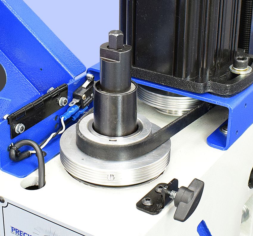
PM-728V-T

                                                            FAQ

      My mill doesn’t run               R8 collets won’t go            The control box              The drawbar doesn’t
                                         into the spindle            beeps when power is          seem to be long enough
                                                                         switched off
                                                                      No problem — this is
                                                                      not a fault condition                1

                                                                                                     3

                                                                                                                2

                                    The collet locating screw
                                    could be in too far. Back it
                                    out a little.                                                 Install the drawbar (1)
                                                                                                  INSIDE the spindle cap
                                                                                                  (2), as here (unscrew cap,
           110 Vac power connected?                                                               insert drawbar into spin-
           GREEN button pressed?                                                                  dle, replace cap)
           Speed control set?
           E-Stop button out? (pop it out                                                         (3) Belt cover microswitch
           by twisting firmly clockwise)                                                          (must close to power-up
           Circuit breaker popped?                                                                the mill)
           Belt cover closed? See photo         photo
           at right, item (3)

               This manual contains essential safety advice on the proper setup, operation, maintenance, and ser-
               vice of the PM-728V-T milling machine. Failure to read, understand and follow the manual may result
               in property damage or serious personal injury.

               There are many alternative ways to install and use a mill. As the owner of the mill you are solely
               responsible for its proper installation and safe use. Consider the material contained in this manual
               to be advisory only. Quality Machine Tools, LLC cannot be held liable for injury or property damage
               during installation or use, or from negligence, improper training, machine modifications or misuse.

               This manual describes PM-728V-T machines as shipped from early 2020. There may be detail dif-
               ferences between your specific machine and the information given here (with little or no impact on
               functionality). Please email us if you have questions about any aspect of the manual or your machine
               (see our website www.precisionmatthews.com for support contacts). Your feedback is welcomed!

                                        Copyright © 2020 Quality Machine Tools, LLC
               This material was originated by Precision Matthews. No portion of the manual may be repro-
               duced or distributed in any form without the written approval of Quality Machine Tools, LLC.

PM 728V-T v3 2022-01                                            2                        Copyright © 2022 Quality Machine Tools, LLC
Section 1 INSTALLATION

                                         THESE ARE THE MAIN POINTS TO WATCH OUT FOR!
                                          But read the following pages for more information

                       •   Handling the mill is at least a two-person job.
                       •   Lower the center of gravity by hand-cranking the headstock down until the spindle nose
                           is just clear of the table.
                       •   Lifting gear – sling, hoist or forklift – must be rated for at least 500 lb.
                       •   The working location of the mill must allow: Full left-right travel of the table, also access
                           to the top of the column (for Z-axis leadscrew maintenance).
                       •   Power requirement is 110V, 60Hz, 1φ, 20A circuit protection.
                       •   Extension cord not to be used
                       •   Before connecting power for the first time be sure that:
                                1. The machine is on a firm footing, adequately secured to bench or stand.
                                2. No chuck or collet is installed.
                                3. The drawbar has been removed (see below).
                                4. There are no clamps or locks on moving parts.
                                5. The speed control knob is set for the lowest speed.

  SETTING UP THE MILL
  The PM-728V-T is shipped in two packing cases, one for the machine and tray (and optional 3-axis DRO), one for
  the stand, if ordered.

  Removing the drawbar                                                 UNCRATING & MOVING THE MILL
  1.   With the table protected by scrap material, loosen the          The following procedure makes use of an engine hoist, min-
       quill lock lever, then lower the quill.                         imum weight rating 500 lb. If a hoist is not available, and you
  2.   Swing open the drive cover in front of the motor, Figure        need to use manpower for lifting, see the dismantling instruc-
       1-1.                                                            tions on the following page.
  3.   While holding the spindle nose with the special C-wrench
       (supplied), use a 17 mm wrench to unscrew and remove            First, no matter what the lifting method is, prepare the bench or
       the spindle cap. See also Figures 3-3 and 3-4.                  optional stand, with the chip tray in its working location.
  4.   Remove the drawbar from the spindle. Re-install the spin-       Highly recommended! Bolt the bench or stand firmly to the
       dle cap, hand-tight.                                            floor. Check working clearances, Section 2.
                                                                       1.   If the handwheels were shipped loose, install the largest
                                                                            of the four at the top of the column. The three smaller
                                                                            handwheels are for the X-axis (2) and Y-axis (1).
                   Drawbar                                             2.   Release the table locks, X-axis and Y-axis.
                                                                       3.   Release the headstock Z-axis locks.
                                                                       4.   Center the table (X-axis), then move the table back to the
                                                                            column as far as it will go (Y-axis).
                                                                       5.   Crank the headstock (Z-axis) down so that the spindle
                                                                            nose is just clear of the table. The mill’s center of gravity
                                                                            should now be as far down and back as possible. Tight-
                                                                            en the Z-axis lock.
                                                                       6.   Unscrew the four nuts securing the mill to the pallet.
                                                                       7.   If necessary, setup the hoist with its legs straddling the
                                                                            machine as follows: 1. Remove one leg from the hoist,
                                              Spindle                       then position the other leg over the pallet, as close to
                                              cap
                                                                            the machine base as possible. 2. Re-install the removed
                                                                            leg, positioning it over the pallet, likewise close to the
               Return
               spring                                                       machine base. 3. Set the hoist arm short enough so that
               cup                                                          the hook is immediately overhead the collar.
                                                                       8.   Run a padded sling under the headstock, as Figure 1-2.
                                                                       9.   Taking care not to damage the Z-axis locking handle
                                                                            and the electrical box, hook the sling, basket style, to the
  Figure 1-1 Access to the drawbar                                          hoist's hook/chain.

PM 728V-T v3 2022-01                                               3                            Copyright © 2022 Quality Machine Tools, LLC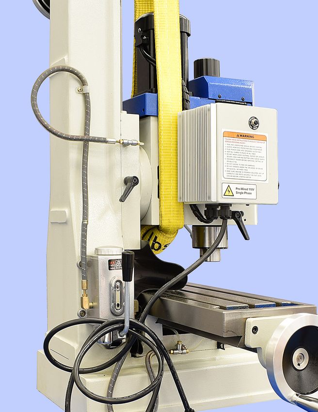
Z-axis
        lock

  Figure 1-2 Sling position

  10. Slowly lift the mill clear of the pallet.
  11. Roll the mill into position over the chip tray, then lower it       Figure 1-3 Lowering the mill into position
      into place, Figure 1-3.
  12. Secure the mill to the bench or stand. If this is a stand in-
      stallation, use the four bolts M8 x 100 mm bolts supplied.
      Use plain and lock washers in all locations.

  OPTIONAL
  PARTIAL DISASSEMBLY OF THE MILL
  If a hoist is not available, and the mill has to be moved by man-
  power, this is more manageable if the headstock and table are
  temporarily removed. Not a one-person procedure.

  Table removal
  1. Remove handwheels, support brackets and other compo-
      nents from both ends of the leadscrew. Set the parts aside
      in separate left-hand/right-hand containers.
  2. Remove the gib from the front dovetail.
  3. Slide table to one side then lift it clear, taking care not to
      damage the dovetails.
  Headstock removal
  1. Assemble a stack of 2 x 4s as Figure 1-4. Lower and lock
     the quill so that the spindle nose rests on the front 2 x 4
     (this is for balance, not for load bearing).
  2. Crank the headstock down to the point where the head-
     stock is felt to be pressing firmly on the back 2 x 4s —
                                                                            Figure 1-4 Removing the headstock
     firmly, meaning the headstock will not suddenly shift
                                                                            Inset: Use a telescoping magnetic pickup
     when its two attachment nuts are loosened.                             tool to retrieve/reposition T-bolts
  3. With another person on hand to stabilize the headstock,
     remove the two attachment nuts, then move the table for-
     ward clear of the T-bolts.

PM 728V-T v3 2022-01                                                  4    Copyright © 2022 Quality Machine Tools, LLC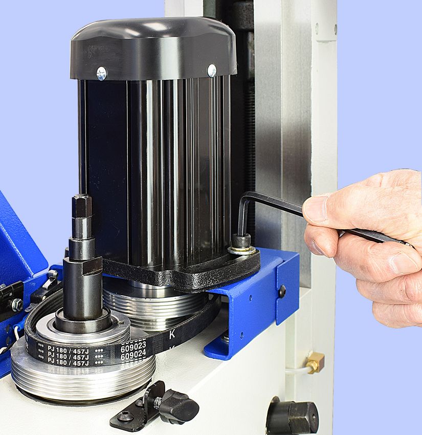
Assembly and cleanup
 Unfinished metal surfaces may be protected in shipping by
 thick grease and/or paper. Carefully remove these using a
 plastic paint scraper, disposable rags and a light-oil such as
 WD-40. Coat bright machined surfaces after cleaning with a
 rust preventative such as Rustlick. Do not leave them bare, or
 rust may stary quickly.
 Level the mill using the table surface for reference, shimming
 under the tray if necessary. If the mill is on the optional stand,
 adjust the leveling feet. Oil the ways and leadscrews (Z-axis
 leadscrew excepted, inaccessible).

  INITIAL CHECKS
  Read Section 3 if unsure about any item in the following

  1.   Check that no chuck or collet is installed, drawbar re-
       moved; no clamps or locks on moving parts.
  2.   Turn the speed control knob fully counter-clockwise (low-
       est speed).
  3.   Open the blue motor cover. Make sure the belt is set for
       low speed (belt running on the larger front pulley.) If not,
       re-position the belt, Figure 3-2. Replace the motor cover.
       Make sure the spindle is free to turn.
  4.   Connect 110 Vac power.
  5.   Be sure the E-Stop (Emergency) button has not been
       pushed in (it should pop out when twisted firmly clock-
       wise).
  6.   Press the green Power button. The power lamp and the
       tach display should light.
  7.   Select FWD spindle direction, then turn the speed knob a
       few degrees to the right. Viewed from above, the spindle
       should rotate clockwise.
  8.   Rotate the speed control knob clockwise for a speed of
       300 to 400 rpm. Run the spindle at that speed for about
       1 minute, then progressively increase the speed to the
       maximum (about 1500 rpm).
  9.   Check the emergency function by pressing the E-Stop
       button. This should disable the power circuit, stopping the
       spindle. You will hear a series of beeps from the electrical
       box once power is disconnected. This is normal.

  If #8 doesn’t happen, the E-stop function is defective,
  and needs attention - This should stop the machine when
  presses

  10. Restore power by twisting the E-Stop button firmly to the
      right; this will cause it to pop out. You can now re-start the
      machine as shown starting in step 6 above.
  11. Re-install the drawbar UNDER the spindle cap, Figure
      1-1.

PM 728V-T v3 2022-01                                                   5   Copyright © 2022 Quality Machine Tools, LLC
Section 2 FEATURES & SPECIFICATIONS
 MODEL PM-728V-T Milling Machine

 General information
 The PM-728V-T is a robust “square column” mill with R8 spindle and continuously-variable spindle speed up to 4000 rpm. It is
 designed for day-in, day-out use in the model shop. With a weight of 370 lbs it can handle far more than the typical machine of its
 size. For precise control of cutter depth there is a worm-driven quill downfeed with graduated dial and built-in DRO, completely
 independent of headstock elevation.

 The reversible spindle runs in high-quality, deep-groove ball bearings enclosed in a robust quill with coarse (drilling) and fine
 (milling) downfeed options. It is powered by a 1 HP (750 W) brushless dc motor. Spindle speed is continuously variable from
 approximately 100 to 1500 rpm, low range, and 300 to 4000 rpm, high range. This is a gearless design with two-step pulleys on
 motor and spindle coupled by a long-life ribbed belt. The headstock can be tilted 90o clockwise and counter-clockwise from the
 vertical. Precision ground dovetailed ways for table and headstock ensure smooth, precise motion in all three axes: X = left/right
 motion of table 19 in., Y = front/back motion of table 10 in., Z = headstock up/down, 16-1/4 in. (Installation of DRO scales on the
 table and headstock may limit these numbers.)

                                                                                                                              76-1/2"
                                                                                                                               max

                                                                                                                    44-1/2"
                                                                                                                     max

                                                                                                                34-3/4

                  8-1/2"

                                                    3-1/4"

                                                                                                                         32

                                    41                                                      30

                                                    PM-728V-T dimensions

PM 728V-T v3 2022-01                                              6                         Copyright © 2022 Quality Machine Tools, LLC
PM-728V-T SPECIFICATIONS
  General
   Power requirement                            110V, 60Hz single phase, 20A circuit
   Approximate weight                           Machine only: 370 lb net, 450 lb shipping
                                                Optional stand: 100 lb net, 110 lb shipping

  Dimensions
   Machine height, no stand                     Normal operations: 36 in.
                                                Head at max elevation: 44-1/2 in.
   Machine height, mounted on stand             Normal operations: 67-1/2 in.
                                                Head at max elevation: 76-1/2 in.
   Stand dimensions                             Height, floor to chip pan surface: 31-1/2 in.
                                                Chip pan: 21-1/2 in. W x 24-3/4 in. D
                                                Footprint: 21 in. W x 20-1/2 in. D
   Floor space required                         Width, full left-right travel of table: 62 in.
                                                Depth, Y-axis handle tip to back of chip
                                                pan: 30 in.

  Table
   Table size                                   7 x 28 in.
   Front-back travel, Y-axis                    With DRO                              No DRO
                                                With full way-support: 7-3/4 in.      8-1/2 in.
                                                Between hard stops: 9-1/2 in.         10 in.

   Left-right travel, X-axis                    With full way-support: 17-3/4 in.
                                                Between hard stops: 19 in.
   Leadscrew pitch, both axes                   10 TPI (0.1 in. per turn)
   Handwheel dials, both axes                   0.001 in. graduations
   T-slots (3)                                  Width: 12 mm (use PM 1/2 in. clamp kit)
                                                Between Slots: 55 mm (approx. 2-5/32 in.)
   Maximum load, centered                       300 lb

  Motor & Headstock
   Motor                                        1 HP brushless dc, variable speed
   Spindle speed                                Continuously variable, 100 to 4000 rpm
                                                in two ranges
   Spindle dimensions                           Internal taper: R8
                                                Drawbar: 7/16-20, 11 mm hex wrench
                                                Top end splines (6): 22 mm OD
   Quill (spindle) travel                       3 in.
   Spindle nose to table                        Zero to 16-1/4 in.
   Spindle centerline to front face of column   8-3/4 in.                                                 T-slot dimensions
   Z-axis leadscrew pitch                       10 TPI, 0.001 in. dial graduations
   Headstock vertical travel                    16-1/4 in.
   Headstock left-right tilt                    90 degrees - zero - 90 degrees

  Typical cutting capacities in steel
  Drilling 3/4 in., End milling 1 in., Face milling (with multi-tip tool) 3 in.

  Special accessory supplied:
  Spindle C-wrench

PM 728V-T v3 2022-01                                                         7                    Copyright © 2022 Quality Machine Tools, LLC
Everyday precautions
                   • This machine is designed for milling and drilling operations by experienced
                   users familiar with metal-working hazards.

                   • Untrained or unsupervised operators risk serious injury.

                   • Wear ANSI-approved full-face or eye protection at all times when using the
                   machine (everyday eyeglasses are not reliable protection against flying particles).

                   • Wear proper apparel and non-slip footwear – be sure to prevent hair, clothing
                   or jewelry from becoming entangled in moving parts. Gloves – including tight-fit-
                   ting disposables – can be hazardous!

                   • Be sure the work area is properly lit.

                   • Never leave chuck keys, wrenches or other loose tools on the machine.

                   • Be sure the workpiece and machine ways are secure before commencing mill-
                   ing or drilling – hold-downs and/or vise fully tightened, X-Y-Z axes locked, cutting
                   tool secured.

                   • Use moderation: light cuts, low spindle speeds and slow table motion give
                   better, safer results than “hogging”.

                   • Don’t try to stop a moving spindle by hand – allow it to stop on its own.

                   • Disconnect 110V power from the mill before maintenance operations such as
                   oiling or adjustments.

                   • Maintain the machine with care – check lubrication and adjustments daily
                   before use.

                   • Clean the machine routinely – remove chips by brush or vacuum, not com-
                   pressed air (which can force debris into the ways).

                                No list of precautions can cover everything.
                                         You cannot be too careful!

PM 728V-T v3 2022-01                                          8                     Copyright © 2022 Quality Machine Tools, LLC
Section 3 USING THE MILL
 HEADSTOCK CONTROLS

           Before doing anything, check
           the installation instructions in                                                                              Head tilt
           Section 1                                                                                         Top cover   adjust
                                                                                                             release
 1. Make sure the direction switch is set
    to OFF. Connect the mill to a 110Vac
    outlet.

 2. Press and release the green Power
    ON button to energize the control cir-
    cuit; the tachometer should light. This                                                      Fine                            Fine feed
                                                                                                 feed                            engage
    is a self-latching circuit – when the ON                                                     knob
    button is released, a contactor in the
    electrical box maintains power until re-                   Spindle
                                                               direction
    leased by the red OFF button (also a
    momentary switch).                               Spindle
                                                     speed
                                                                                                                                Drill press
 3. The large red E-stop button is in se-                                                                                       levers
    ries with the OFF button. Like the OFF                 Quill           Quill                                                (coarse
    button it de-energizes the control cir-                lock            DRO                                                  feed)
    cuit completely, but it should be used
    only for emergency disconnect. Once
    the E-stop button is pushed in, it stays
    in until twisted firmly clockwise to re-
    lease.                                                                                                     Figure 3-1 Headstock controls

 4. The spindle motor is controlled by a
    three position switch, Forward/Stop/
    Reverse, and a continuously-variable
    speed control knob.

 FWD = Forward (clockwise, looking down,
       used for most milling and drilling
 OFF = Stop
 REV = Reverse (counter-clockwise, look-
       ing down)

    Always use the Direction Switch, not the
    Power buttons, to turn the spindle on and off,
    except during an emergency

    Use the Power Buttons only to power-up
    and power-down the mill.

    When powering-down, it is normal to hear a
    series of beeps from the electrical box.

  SPINDLE SPEEDS
  The PM-728V-T is a belt-driven machine with two speed rang-
  es, (L) 100-1500 rpm and (H) 300-4000 rpm.

  To select a speed range, disconnect power, then open the top
  cover. Loosen the socket head screws on each side of the
  motor, then swing the motor forward to free the belt, Figure                                                    Figure 3-2 Belt adjustment
  3-2. Make sure that the ribbed belt is properly engaged with
  the selected pair of grooved pulleys, then re-tighten. Before                    Excessive cutter noise, chatter, poor finish and tool
  powering up, rotate the spindle by hand to check tracking and                    wear are often the result of too high a feed rate, and/
  tightness of the belt. Do not over-tighten – aim for ± ¼” slack                  or too high a spindle speed. If unsure, go slow!
  between the motor and spindle pulleys.

PM 728V-T v3 2022-01                                                   9                             Copyright © 2022 Quality Machine Tools, LLC
INSTALLING AND REMOVING TOOLING

  The spindle and drawbar are designed for R-8 taper collets,                    Drawbar
  drill chucks and other arbors with the standard 7/16”-20 inter-
  nal thread.

                                                                                                             Spindle
  Figure 3-3 Spindle schematic                                                                               cap

                                                                             Return
                                                                             spring
                                                                             cup

                                                                                                  Figure 3-5 Two-step belt drive
                                                                                           The drawbar collar, Figure 3-2, must be
                                                                                               UNDER the spindle cap, as shown

  Figure 3-4 Spindle disassembled (drawbar omitted)

  Two tools are required to install or remove R8 tooling: an 11 mm
  wrench for the square drawbar nut, and the supplied C-wrench
  which engages in flats at the bottom end of the spindle.

  R8 tooling is located in the spindle bore by an M4 x 6 mm
  long set screw. If it is difficult or impossible to insert the
  R8 device, chances are the set screw is in too far. Rotate
  the spindle by hand to expose the screw, Figure 3-6, then
  back it out a fraction of a turn using a 2 mm hex wrench.

  Hand rotate the spindle again to check that the screw
  clears the inside surface of the quill.                                                            Figure 3-6 Collet set screw
  Installing R8 tooling
  Install the R-8 device, then hand-thread the drawbar into it until
  the drawbar collar bottoms on the splined spindle (on the ma-
  chine itself this action is concealed by the spindle cap, Figure
  3-3). Fully tighten the drawbar with an 11 mm wrench, while at
  the same time holding the spindle stationary with the special
  C-wrench, page 7. [Do NOT try to hold the spindle using the
  flats on the spindle cap.]
  Removing R8 tooling
  Protect the table, vise or workpiece under the spindle with rags
  or scrap wood. Why? Because they can easily be damaged by
  falling tools and drill chucks. The cutting tool itself can also be
  damaged in the same way.

  Lock the spindle with the C-wrench, loosen the drawbar one
  turn or less, just enough to unseat the taper, then tap the top
  of the drawbar with a brass or dead-blow hammer to break the
  taper seal. Unscrew the drawbar with one hand while support-
  ing the R-8 device with the other hand.

PM 728V-T v3 2022-01                                                    10            Copyright © 2022 Quality Machine Tools, LLC
MOVING THE TABLE & HEADSTOCK location, see “Positioning by Counting X-Y Divisions”, later in
Conventionally, left-right movement of the table is said to be this section.
along the X-axis (also called “longitudinal travel” or “travers-
ing”). Leadscrew handwheels are provided at both ends of the LOCKING THE AXES
table, Figure 3-7. Front-to-back movement is along the Y-axis, Before machining a workpiece it is usually necessary to po-
sometimes called “cross travel”. The Y axis leadscrew has a sition the table precisely, then lock either the X or the Y axis,
single handwheel at the front, Figure 3-8. sometimes both (for drilling and similar operations). You can
also use the lock levers to apply a light drag to the axis in
Headstock motion is in the Z-axis, in line with the vertical col- motion. This can help reduce chattering (better surface finish)
umn. The headstock is raised and lowered by a handwheel at and also lessen the chance of overshooting inadvertently. To
top right of the column, Figure 3-9. reduce wear, free the levers once the operation is completed.
Figure 3-10 X-axis locks
Figure 3-7 X-axis handwheel & dial (right hand)
Figure 3-11 Y-axis lock
Figure 3-8 Y-axis handwheel & dial
2
1
Figure 3-12 Z-axis lock (1)
Also shown here (2) is one of two headstock attachment nuts.
When possible, operations calling for precise
depth control (such as milling) should be done
with the headstock locked, also with the quill
Figure 3-9 Z-axis handwheel & dial
fully retracted into the headstock and locked.
Each axis has a leadscrew with handwheel and graduated dial
with 0.001” divisions, 0.1” per revolution, Figures 3-7 to 3-9.
If the mill is not equipped with digital readouts (DROs), the
table and headstock can be accurately positioned by count-
ing whole turns and divisions, keeping leadscrew backlash
in mind. This means that motion must always be in the same
direction up to the point of reference, then on to the desired
PM 728V-T v3 2022-01 11 Copyright © 2022 Quality Machine Tools, LLCQUILL DOWNFEED
The quill is controlled in two different ways, coarse and fine.
6
For drilling operations, coarse feed, the milling machine oper-
ates like a standard drill press with a 3-lever hub. Lever action
lowers or raises the quill in the usual way by rack and pinion.
Return action is assisted by a compression spring within the
quill and spindle assembly, Figures 3-3 and 3-4.
For milling operations the lever hub is not usually rotated by
lever action. Instead it is driven through worm gears turned by 5
the fine control knob, Figure 3-13 (2). This allows the quill to be
driven precisely to any desired position. The fine control knob,
because it drives through a worm, cannot be back-driven by 1 4
return-spring action on the quill (in other words, it stays where 2
it’s put). For milling operations the quill should, when possible,
be fully retracted, then locked by the lever on the left of the
headstock, Figure 3-1.
3
Coarse feed (Figure 3-13)
For drilling operations, loosen knob (4), allowing the lever hub
(1) to rotate independently of sleeve (3).
Fine feed (Figure 3-13)
For milling operations calling for precise, repeatable control of
tool depth, tighten knob (4) to engage hub (1) with the internal Figure 3-13 Quill downfeed controls
The lever hub (1) is connected at all times to the quill pinion, which
taper on sleeve (3). Tighten the Z-axis lock, Figure 3-12. engages a rack on the back side of the quill. The fine control knob (2)
drives sleeve (3) through a worm gear. If clamp knob (4) is unscrewed,
Rotate the fine control knob (2) to raise or lower the quill. Low- both (2) and (3) rotate freely, doing nothing to the quill. Fine feed is
er the quill by rotating the fine control knob clockwise, position- engaged by tightening knob (4) to clamp (3) and (1) together. The
ing it precisely either by counting divisions on the graduated depth dial, graduated in 40 mil (0.04") increments, is locked to sleeve
dial, or by reference to the quill digital readout (DRO), Figure (3) by thumbscrew (5).
3-1. Use the locking lever left of the headstock to hold the quill
firmly in position. Worm shaft (6) enables precise adjustment of the headstock tilt angle.
If you are counting downfeed divisions be
aware of backlash in the worm drive.
The quill DRO – which has no backlash issues – offers a less
laborious way of setting tool height, but bear in mind that the
quill is spring-loaded.
This calls for care when releasing the quill locking lever. If the
fine control knob has been allowed to disengage (backed off
counter clockwise), the quill may jump up by 0.01” or more. To
avoid this, make sure the fine control has been turned clock- Figure 3-14
wise to apply downward pressure on the quill before the lock- Quill depth dial
ing lever is released.
POSITIONING BY COUNTING X / Y DIVISIONS
QUILL DRO For all spindle positioning operations avoid using the
The quill DRO is in metric mode when switched on. Press quill lock. When possible, retract the quill fully, then
the mm/in button to display inches. adjust the headstock elevation instead.
Why? On practically all vertical mills, including the heavier
Replace the battery by removing the small molded cover knee mills, locking the quill may offset the spindle by a few
on the face of the DRO unit (align the dots). Check the thousandths of an inch. For milling operations this is not a
type number and voltage of the installed battery. Replace problem provided edge "finding" and subsequent machining
with an equivalent (LR44) silver oxide cell available from are both done with the quill retracted and locked.
local retailers.
Drilling, on the other hand, is quite different. If the edge of the
workpiece has been “found” with the quill locked, this may af-
Switch off the DRO when not in use! fect placement of holes drilled thereafter. Instead, do the find-
ing by lowering the headstock, or lower the quill with the fine
downfeed control — no locking in either case.
PM 728V-T v3 2022-01 12 Copyright © 2022 Quality Machine Tools, LLCusual tap drill charts. Typically, a 10% reduction in drill size
below nominal causes no real difference in holding power or
thread integrity under load.
TILTING THE HEADSTOCK
In routine operations the user relies on squareness of the spin-
dle relative to both axes of the table. Front-to-back squareness
is set at the factory, and is not adjustable by everyday meth-
ods. In the other plane, the headstock can be set to any angle
up to 90 degrees either side of the normal vertical position.
Because re-establishing true vertical (tramming) on any mill is
Figure 3-15 Workpiece positioning example
a time consuming process, most machinists look first for other
ways of handling a project instead of tilting the head.
In this illustration a hole is to be drilled exactly 0.25” on the
Y-axis relative to the front edge of a workpiece in a vise, or The headstock is secured by two nuts spaced on either side,
otherwise clamped to the table, Figure 3-15. Figure 3-12. The headstock is top-heavy, and may swing sud-
denly to either side unless a helper is on hand to restrain it.
1. Install an edge-finder in collet or chuck (a tip diameter of Testing for movability as you go, carefully loosen the nuts by
0.2” is assumed). degrees. Be especially careful if the head has not been moved
2. Lock the X-axis (optional). before — the paint seal may let go without warning. (First-time
3. If the reference edge is already to the back the spindle tilting may also call for unusual effort on the wrench.)
centerline, do nothing; if not, rotate the Y-axis handwheel
clockwise to send the workpiece backwards (toward the Set the headstock to the desired tilt using a digital angle indi-
column). cator such as Figure 3-16. Insert a length of bar stock, ideally
4. Engage the fine downfeed, Figure 3-13. ground, in a collet of known accuracy (check for runout at the
5. With the spindle running, lower the quill as necessary tip). Angle indicators like this are typically good within ± 0.2o. If
using the fine downfeed control, then bring the table for- the project calls for greater accuracy a more accurate means
ward (counter-clockwise), stopping at the point where the of angle measurement will be needed.
edge-finder just makes contact (the tip jumps out of line).
Stop the spindle. Fine adjustment of tilt angle is made easier by a worm shaft
6. While holding the Y-axis handwheel to prevent rotation, & worm wheel combination. The worm shaft, Figure 3-13 (6),
zero the Y dial. engages a worm wheel secured to the headstock casting, Fig-
7. Raise the quill, then rotate the handwheel one exact full ure 3-17 inset. Use a 21 mm wrench to turn the worm shaft.
turn counter-clockwise (0.1”) to bring the reference edge
to the spindle centerline.
8. Rotate the handwheel 2-1/2 turns counter-clockwise to
bring 50 on the dial opposite the datum; the spindle is now
precisely 0.25” to the back of the reference edge.
TAPPING OPERATIONS
When threading a drilled hole it is essential to align the thread-
ing tap properly in the bore. The mill is often used for this
purpose, ideally with a dedicated (non-slip) tap holder or, for
production work, an auto-reverse tapping attachment, e.g.,
Tapmatic.
A drill chuck can be used instead for sizes up to (say) M6 or
Figure 3-16 Headstock tilt angle measurement
1/4”, beyond which the chuck may not grip tightly enough to Use the indicator's relative mode to measure the angle
avoid slippage. Tapping can be done under power, or by hand between the spindle and the surface of the workpiece.
turning the chuck.
For either method, it is essential to use a tapping fluid. Any cut-
ting oil is better than none, but most users find Castrol’s Moly
Dee the most reliable for threading in steel.
If power tapping, bear in mind that the spindle does not stop
instantaneously, so be careful tapping blind holes. Free the
quill locking lever. Start with the lowest spindle speed. Coun-
teract the effect of the quill's return spring by applying gentle
downward pressure on the quill while feeding in the tap. (This
is to reduce lifting force on the workpiece, which tends to pull
the workpiece out of the chuck.) For easier tapping it may be
helpful to experiment with a larger hole than specified in the Figure 3-17 Headstock worm wheel
PM 728V-T v3 2022-01 13 Copyright © 2022 Quality Machine Tools, LLCTRAMMING THE HEADSTOCK 10. Swing the indicator holder to the new location, then lower
As shipped, the mill is set to zero tilt, squared accurately the spindle – fine downfeed again – to give the same dial
enough for initial test drillings, etc., out of the crate For more indicator reading as in step (8).
demanding project work thereafter, the spindle needs to be
set at precisely 90 degrees relative to the table, in other words If the headstock is perfectly trammed – highly unlikely at the
trammed. “Out of tram” may show up as an offset of a few first shot – the DRO reading should be as in step (8). If not,
thousandths between entry and exit of a deep hole, or as a loosen the nuts just enough to allow the headstock to allow
scalloped effect when surfacing a workpiece with a large-radi- very small adjustments — fractions of a degree — by turning
us fly cutter, greatly exaggerated in Figure 3-18. the worm shaft, Figure 3-13 (6). Re-tighten the nuts.
Repeat steps (7) through (10) until satisfied with the tram,
tightening the nuts as you go. This will likely call for several
iterations. There is no “right” tram; the acceptable difference in
side-to-side readings depends on project specs. As a starting
point, aim for ± 0.002” with a sweep radius of 5 or 6 inches.
Figure 3-18 Head tilt affects surface flatness
This is the effect, much exaggerated, if the head is tilted minutely out
of square when milling a surface with a large diameter cutter. In the
other axis the scalloping effect would be at right angles (hashed red
line) if the head is tilted forward or back, and the table is moved in the
Y-axis.
Tramming is done by fine-tuning the headstock tilt angle.
Check the tram by attaching a dial indicator to some form of
“sweepable” holder installed in the spindle. The aim is to adjust
tilt for the same reading on either side of the X axis. The longer Figure 3-19 Shop-made indicator holder
the radius arm, the greater the sensitivity.
Tramming calls for patience! Expect to tighten and
Figure 3-19 shows a typical shop-made holder; it has a thread- re-check several times (simply tightening the head-
ed arbor allowing the choice of two radius arms, 6 and 10 inch- stock attachment nuts can itself affect the tram)
es measured from spindle centerline to indicator tip. A collet
is used to hold the arbor, in this example 5/8” diameter. The
dimensions are arbitrary, but note that the indicator must be A similar procedure may be used to check tram in the Y-axis,
firmly attached, with the arm rock-solid relative to the indicator front to back. Tram error in the Y-axis may show up as a scal-
spring force (which can be considerable on plunger-type indi- loping effect when fly cutting a nominally flat surface, Figure
cators). 3-18, red hashed line. Y-axis tram is established in manufac-
ture, and should be adequate for most purposes.
A suggested procedure for establishing tram:
If more precise tram is called for, it can be adjusted by sand-
1. Disconnect power. wiching a metal shim between the headstock and its sliding
2. Install the dial indicator. base (saddle) on the column. It is more likely that the head-
3. If the headstock has been tilted, reset it to the approximate stock is nodding forward rather than leaning backward, so start
zero degree position on the tilt scale, then tighten the two with (say) a 1 mil (0.001") shim in the bottom quadrant of the
nuts enough to avoid unexpected headstock movement. machined mating surfaces between headstock and saddle.
4. Remove the vise, if installed, and clean the table surface. This is a temporary fix that may not be satisfactory if the head-
If there are noticeable grooves or dings, flatten the surface stock is subsequently rotated.
with a diamond lap or fine-grit stone.
In all bench mills there is a tendency for Y-axis tram to
5. Set a 1-2-3 block (or other precision-ground block) on the
vary minutely as the headstock elevation is changed
table under the indicator probe.
— select the "most used zone" when shimming
6. Switch on the quill DRO.
7. Using the fine downfeed lower the spindle to give an indi-
cator reading of about half-scale.
8. Note the dial indicator and DRO readings, then back off
the fine downfeed at least a couple of turns to avoid colli-
sion when sweeping.
9. Reposition the 1-2-3 block to the opposite location on the
table.
PM 728V-T v3 2022-01 14 Copyright © 2022 Quality Machine Tools, LLCINSTALLING & INDICATING A VISE VISE KEYS
For routine milling operations the workpiece is held in a preci- Most precision vises come with key slots on the underside ma-
sion vise. For the PM-728V-T a 4” vise is most suitable. chined exactly parallel to the fixed jaw. Key slots, Figure 3-21,
can be a great time saver. Properly installed they allow the
“Indicating” means checking the alignment of the fixed (back) vise to be removed and replaced routinely, accurately enough
vise jaw relative to the axis of table motion. for general machining without the need for indicating every
time.
Install the T-bolts and align the vise by eye. With one of the
clamp nuts snug, but not tight, tighten the other one just short Most 4” vises have either 14 mm or 16 mm slots, calling for
of fully-tight (but tight enough so the vise won’t budge without shop-made T-shape adapter keys as Figure 3-22. It is well
a definite tap from a dead-blow mallet). worth the effort to make these precisely. Aim for a snug fit in
both vise and table, but not so tight that it takes more than a
A typical setup for indicating is shown in Figure 3-20. There is small amount of effort to lift the vise clear. Case hardening is
no spindle lock, but you need to make sure that the spindle recommended, with final fitting using a fine stone or diamond
does not rotate throughout the procedure — it helps if the low stone.
spindle speed is selected.
Set the indicator tip against the upper edge of a precision ref-
erence bar or, if not available, use the front face of the fixed
jaw of the vise instead (check for dings, hone if necessary).
Adjust the Y-axis to pre-load the indicator to mid range at the
tightly-clamped side of the vise, then lock the Y-axis.
Note the indicator reading, then watch the indicator as you
traverse the table slowly toward the loosely clamped side —
watch for any sign of spindle rotation. Ideally, there should
be no discrepancy between the indicator readings at the two
ends — unlikely at the first attempt. Return the table to the
starting point, then repeat the process, tapping the vise in as
you go. Repeat the process as often as necessary for the de-
sired accuracy, progressively tightening the “looser” nut. Now
fully tighten both nuts, and re-check again (tightening a nut
can itself introduce significant error). An established routine
like this – tight to loose – can save a lot of time. Figure 3-21 Vise keys installed on X-axis
On most vises the keys can also be installed on the long axis.
Most users aim for an end-to-end difference of not more than
± 0.001” over the width of the vise jaw.
Figure 3-22 Shop-made vise key
Dimensions in millimeters
Figure 3-20 Indicating the vise
The tip of a standard dial indicator, arrowed, rides along the side face
of a ground reference bar (or the front face of the back jaw).
PM 728V-T v3 2022-01 15 Copyright © 2022 Quality Machine Tools, LLCSection 4 MAINTENANCE ble movement. Too tight means accelerated wear on the ways
and leadscrews. Too free means workpiece instability, inaccu-
racies and chatter.
Unplug the 110V power cord before any
maintenance operation! Both screw heads must be tight against the gib ends. If you
loosen one, tighten the other. Remove the way covers for ac-
cess to the back of the Y gib and bottom of the Z gib.
Remove all machining debris and foreign objects
before lubricating ANYTHING! If need be, any oil is
better than no oil – but use the recommended lubri-
cants when you can.
RECOMMENDED LUBRICANTS
One-shot oiler: ISO 68 way oil, such as Mobil Vactra No. 2,
or equivalent
Visible gears such as quill rack and pinion, Z-axis bevel
gears: light general purpose grease, NLGI No. 2, or equiva-
lent
X, Y and Z leadscrews: ISO 68 way oil, Vactra No. 2, or
equivalent
General lubrication of parts not one-shot oiled: General
purpose ISO 68 way oil
GENERAL OILING Figure 4-2 Z-axis gib adjustment, upper screw
Assuming a clean environment – no abrasive particles or ma- The lower screw is under the solid rubber way cover.
chining debris – lack of proper lubrication is the main cause of
LEADSCREW BACKLASH CORRECTION
premature wear. There should a small amount of seepage of
When alternating between clockwise and counter clockwise ro-
oil from the mating surfaces lubricated by the one-shot oiler,
tation of the X or Y leadscrews, the handwheel moves freely a
namely the X, Y and Z dovetails. Be concerned if no seepage
few degrees but the table stays put. This is backlash, a feature
is visible.
of all leadscrews other than the precision type found on CNC
machines. The acceptable amount of lost motion depends on
A high-pressure air line can force sharp particles into the gaps
the user, but between 0.005” and 0.010" is generally a good
between machine ways, and is not recommended for removing
compromise. Smaller numbers are possible, but overdoing it
debris. Brushing off with a disposable paint brush is preferred.
can lead to premature wear of leadscrew and nut.
Operate the one-shot oiler every few hours of operation. Use
Excessive backlash can be corrected by compressing the
a dedicated short-bristle brush to apply oil to the leadscrews,
leadscrew split nut. For the X-axis this is done by tightening
and to the visible portions of the quill rack and pinion.
the socket head screw in Figure 4-3. Use a long-handled 4 mm
hex wrench, or (better) a multi-tool with a 4 mm insert.
GIB ADJUSTMENT
Gibs on the X, Y and Z axes control the fit of the mating dove-
tailed surfaces. They are gently-tapered lengths of ground cast
iron located by opposing screws at each end. Adjusting them is
a trial and error process that takes time and patience. Aim for
the best compromise between rigidity and reasonably free ta-
1
2
Figure 4-1 Gib adjustment, X and Y axes Figure 4-3 Table (X-axis) leadscrew nut adjustment
The left adjustment screw for the X axis is in a similar location to (1) Table removed for visibility. The screw is accessible from the
on the left side of the saddle casting. The back adjustment screw for left side with a long-handled 4 mm hex wrench. Also seen in
the Y axis gib (2) is under the solid rubber way cover behind the table. this photo are machined oil grooves fed by the one-shot oiler.
PM 728V-T v3 2022-01 16 Copyright © 2022 Quality Machine Tools, LLCThe corresponding adjustment for the Y-axis is shown in Fig- SERVICING QUILL & SPINDLE
ure 4-4. In the normal use the quill assembly needs only oiling on
its sliding surface. The spindle runs on pre-lubricated deep-
groove ball bearings and needs no routine attention. If the
bearings need to be serviced or replaced, remove the quill/
spindle assembly as follows:
IMPORTANT: Use wood blocks or other means to protect the
table, and to prevent unexpected downward movement of
the quill assembly.
1. Remove any installed R8 device from the spindle.
Figure 4-4 Y-axis leadscrew nut adjustment 2. Lock the spindle with the C-wrench, then unscrew the spin-
Use a ratcheting wrench with a 4 mm hex insert. dle cap (17 mm flats) from the spindle.
3. Remove the drawbar.
For access to the leadscrew nut, remove the two screws se- 4. Press down on the return spring cup while removing the
curing the flange casting at the front. Unscrew the leadscrew, C-Clip, Figure 4-6.
then slide the saddle/table assembly forward as in Figure 4-5. 5. Remove the return spring, Figure 4-7.
6. Using a 2.5 mm hex key remove the two button head
screws securing the DRO scale and stand-off block to the
quill assembly.
7. Loosen the quill lock lever, then remove the quill assembly
from the headstock.
Figure 4-5 Withdrawing the Y-axis leadscrew
DOWNFEED RETURN SPRING
The quill should automatically retract when the coarse down-
feed levers are released following a drilling operation. If it does
not, check for binding in the quill lock. The return spring, Figure
4-7, is held by a spring cup which is locked to the spindle by
a special C-clip beneath the spindle cap, Figure 4-6. Spring
force is not adjustable.
Figure 4-7 Quill return spring
Spindle
cap
Return
spring cup
Figure 4-6 Removing the special C-clip
PM 728V-T v3 2022-01 17 Copyright © 2022 Quality Machine Tools, LLCSection 5 PARTS
There may be detail
between this repres
and the machine as
MOTOR CONTROLLER PCB ASSEMBLY
Short beeps Possible cause
Series of beeps Powering-down, nor-
after pressing stop, mal operation
or disconnecting
power
Two beeps Low voltage (motor is
running)
Three beeps Overload
Four beeps Over-heating
Five beeps Over-voltage
Six beeps Over-current
Seven beeps EEPROM error
WARNINGS
Long beeps Possible cause Note
Two beeps Bus voltage is lower F_058=250.0
than 250Vdc
Three beeps Output current is F_056 =7.0
higher than 7A
Four beeps Drive temperature is F_057=80.0
higher than 80 ° C
Model PM-728V-T Electrical Fig 1
PM 728V-T v3 2022-01 18 Copyright © 2022 Quality Machine Tools, LLCl differences
sentative drawing
s supplied
PM 728V-T v3 2022-01 19 Copyright © 2022 Quality Machine Tools, LLCModel PM-728V-T HEADSTOCK & SPINDLE Fig 2
53 There may be detail differences
between this representative drawing
and the machine as supplied
PM 728V-T v3 2022-01 20 Copyright © 2022 Quality Machine Tools, LLCModel PM-728V-T HEADSTOCK & SPINDLE Fig 2 Ref Description Part Ref Description Part 1 Spindle cap Z5962 39 Ball bearing 6005ZZ Z6000 2 Draw bar Z5963 40 Quill Z6001 3 C-clip, spring cup retainer Z5964 41 Bearing spacer Z6002 4 Return spring cup Z5965 42 Ball bearing 7007 Z6003 5 Return spring Z5966 43 Spindle Z6004 6 Front plate Z5967 44 Bearing cover Z6005 7 Spindle pulley Z5968 45 Drawbar cover Z6006 8 Bearing 6209ZZ Z5969 47 Drive cover Z6007 9 Spindle sleeve Z5970 48 Drive rear cover Z6008 10 Tach disk Z5971 49 Clamp screw Z6009 11 Ball bearing 6007ZZ Z5972 50 Clamp bracket Z6010 12 Lock lever Z5973 51 Hinge base Z6011 13 DRO bracket Z5974 52 Cover hinge Z6012 14 Sensor Z5975 53 Set Screw M4x.7x6 Z7536 15 Pin Z5976 806 Microswitch Z6013 16 Worm shaft Z5977 901 Phl. hd. screw Z6014 17 Knob Z5978 902 Key Z6015 18 DRO back plate Z5979 903 Set screw Z6016 19 DRO assembly Z5980 904 Ext. retaining ring Z6017 20 Scale bracket Z5981 905 Nut M3 Z6018 21 Motor Z5982 906 Screw Z6019 22 Motor pulley Z5983 907 Cap screw Z6020 23 Belt Z5984 908 Phl. hd. screw Z6021 24 Motor base Z5985 909 Cap screw Z6022 25 Head casting Z5986 910 Nut Z6023 26 Set screw Z5987 911 Cap screw Z6024 27 Head tilting worm shaft Z5988 912 Lock washer Z6025 28 Pinion shaft Z5989 913 Washer Z6026 29 Worm wheel Z5990 914 Key Z6027 30 Flange Z5991 915 Cap screw Z6028 31 Dial Z5992 916 Lock washer Z6029 32 Spring Z5993 917 Washer Z6030 33 Clamp knob Z5994 918 Key Z6031 34 Lever knob Z5995 919 Cap screw Z6032 35 Handle lever Z5996 920 Cap screw Z6033 36 Pinion shaft hub Z5997 921 Phl. hd. screw Z6034 37 O-ring Z5998 922 Nut Z6035 38 Spindle nut Z5999 PM 728V-T v3 2022-01 21 Copyright © 2022 Quality Machine Tools, LLC
PM 728V-T v3 2022-01
22
                                              There may be detail differences
                                              between this representative drawing
                                              and the machine as supplied

                                                                                    Model PM-728V-T TABLE & COLUMN Fig 3

Copyright © 2022 Quality Machine Tools, LLC
Model PM-728V-T TABLE & COLUMN Fig 3 Ref Description Part Ref Description Part 12 Lock lever Z6036 140 Leadscrew flange Z6071 101 Handle Z6037 141 X-axis lead screw Z6072 102 Handwheel Z6038 142 Locking thumb screw Z6073 103 Graduated dial Z6039 143 Way cover Z6074 104 Thrust bearing 51202 Z6040 903 Set screw Z6075 105 Leadscrew flange Z6041 909 Cap screw Z6076 106 Ball bearing 6002ZZ Z6042 911 Cap screw Z6077 107 Y-axis lead screw Z6043 913 Washer Z6078 108 Backing plate Z6044 916 Lock washer Z6079 109 Dovetail guard Z6045 917 Washer Z6080 110 Stop block Z6046 923 Nylon hex nut Z6081 111 Gib adjustment screw Z6047 924 Washer Z6082 113 X-axis leadscrew nut Z6048 925 Cap screw Z6083 114 Gib Z6049 926 Woodruff key Z6084 115 Y-axis leadscrew nut Z6050 927 Phl. hd. screw Z6085 116 Chip pan Z1011 928 Cap screw Z6086 117 Lock lever Z6052 930 Washer Z6087 118 Leadscrew cover A Z6053 931 Cap screw Z6088 119 Leadscrew cover B Z6054 932 Cap screw Z6089 120 Saddle Z6055 933 Cap screw Z6090 122 Head tilt worm wheel Z6056 934 Set screw Z6091 123 T-bolt Z6057 935 Cap screw Z6092 126 Headstock base Z6058 936 Cap screw Z6093 128 Column cover Z6059 937 Hex nut Z6094 129 Column Z6060 938 Lock washer Z6095 130 Bevel gear Z6061 939 Key Z6096 131 Z-axis gear bracket Z6062 940 Retaining ring Z6097 132 Z-axis crank shaft Z6063 941 Hex hd. bolt Z6098 133 Hand wheel Z6064 942 Cap screw Z6099 134 Thrust bearing 51102 Z6065 943 Nut Z6100 135 Z-axis leadscrew Z6066 L01 One-shot oiler Z6101 136 Leadscrew nut Z6067 L02 Phl. hd. screw Z6102 137 Machine base Z6068 L03 Screw Z6103 138 Table Z6069 L04 Tubing Z6104 139 Movable stop sleeve Z6070 PM 728V-T v3 2022-01 23 Copyright © 2022 Quality Machine Tools, LLC
Model PM-728V-T ELECTRICAL COMPONENTS Fig 4

         There may be detail differences
         between this representative drawing
         and the machine as supplied

   Ref Description                             Part         Ref Description                                       Part
   801    ON/OFF switch                        Z6105        810   Cable bushing                                   Z6114
   802    Tachometer                           Z6106        811   Connector mount                                 Z6115
   803    Control panel                        Z6107        812   E-stop button                                   Z6116
   804    Contactor                            Z6108        813   Fwd/Rev selector switch                         Z6117
   805    Overload Switch                      Z6109        814   Speed potentiometer                             Z6118
   806    Limit switch                         Z6013        815   Power cord                                      Z6119
   807    Motor Control Board                  Z6111        907   Cap screw                                       Z6020
   808    Cable bushing                        Z6112        927   Phl. hd. screw                                  Z6085
   809    Electrical box                       Z6113

PM 728V-T v3 2022-01                                   24                          Copyright © 2022 Quality Machine Tools, LLC
Model PM-728V-T STAND Fig 5
There may be detail differences
between this representative drawing
and the machine as supplied
Ref Description Part Ref Description Part
210 Front panel Z6122 917 Washer Z6131
211 Leveling screw Z6123 948 Hex screw M8 x 100 Z6132
212 Top/bottom panel Z6124 949 Nut M8 Z6133
213 Door Z6125 950 Hex screw M8 x 20 Z6134
214 Handle Z6126 951 Nut M6 Z6135
215 Shelf Z6127 952 Cap screw Z6136
216 Rear panel Z6128 953 Carriage screw M8 x 20 Z6137
217 Side panel Z6129 954 Washer Z6138
913 Washer Z6130 955 Nut 1/2 Z6139
PM 728V-T v3 2022-01 25 Copyright © 2022 Quality Machine Tools, LLCYou can also read