Steam Use Efficiency & Demand Reduction - Con Edison Steam Business Development October 2013
←
→
Page content transcription
If your browser does not render page correctly, please read the page content below
Con Edison Steam
Best Practices Report
Steam Use Efficiency & Demand Reduction

Con Edison Steam Business Development
October 2013

                                          Page | 1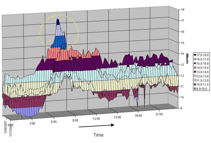
This page was intentionally left blank.

                                          Page | 2
Table of Contents

I.         Introduction .......................................................................................................................................................................... 5
II.        Reference Explanation of Demand Billing ................................................................................................................ 7
III.             Economic Performance Summary ........................................................................................................................... 8
IV.              Energy Efficiency Measures ....................................................................................................................................... 9
      a.         General Energy Efficiency Measures ........................................................................................................................ 9
           i.        Insulation of Steam Distribution Piping, Valves, and Fittings................................................................. 9
           ii.       Steam Leak Repair ................................................................................................................................................. 10
      b.         Heating Distribution Energy Efficiency Measures............................................................................................ 12
           i.        Installation of a Building Management System.......................................................................................... 12
           ii.       Radiator System Optimization .......................................................................................................................... 12
           iii. Implementation of Night Setback .................................................................................................................... 14
           iv.       Installation of Programmable Clock Thermostats .................................................................................... 14
           v.        Reduction of Winter Operating Temperatures .......................................................................................... 14
           vi.       Utilization of Rejected Heat ................................................................................................................................ 15
           vii. Demand Control Ventilation .............................................................................................................................. 15
      c.         Steam Air Conditioning Energy Efficiency Measures ...................................................................................... 16
           i.        Raise Summer Operating Temperatures ...................................................................................................... 16
           ii.       Utilization of a Waterside Economizer .......................................................................................................... 16
           iii. Utilization of an Airside Economizer.............................................................................................................. 16
           iv.       Replacement of Low Pressure Absorption Chillers.................................................................................. 16
           v.        Insulation of Chilled Water Distribution Piping, Valves, and Fittings .............................................. 17
      d.         Condensate Management .......................................................................................................................................... 18
           i.        Condensate Heat Recovery ................................................................................................................................. 18
           ii.       Condensate Reuse .................................................................................................................................................. 19
      e.         Domestic Hot Water (DHW) Energy Efficiency Measures ............................................................................. 20
           i.        DHW Recirculation Controls .............................................................................................................................. 20
           ii.       Reduction of DHW Temperatures ................................................................................................................... 20
      f.         Building Envelope ........................................................................................................................................................ 21
           i.        Weatherization of Building Envelope ............................................................................................................ 21
           ii.       Installation of Window Film .............................................................................................................................. 21
           iii. Replacement of Single Pane Windows........................................................................................................... 21
      g.         Facility Maintenance and Management Practices ........................................................................................... 22
                                                                                                                                                                                       Page | 3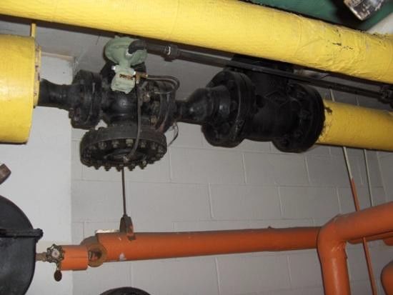
i.        Integration of Steam Demand Meter Data into BMS ................................................................................ 22
          ii.       Steam Trap Inspection and Maintenance ..................................................................................................... 22
          iii. Expansion Joint Replacement............................................................................................................................ 24
          iv.       Installation of Sub-Metering .............................................................................................................................. 24
          v.        Establishment of a “Green” Policy for Hotels .............................................................................................. 24
V.        Demand Reduction Measures ..................................................................................................................................... 25
     a.         Heating Distribution Demand Reduction Measures ........................................................................................ 25
          i.        Application of the STEEMs Method................................................................................................................. 25
          ii.       Steam Load Shifting ............................................................................................................................................... 25
          iii. Adjustment of Air Handling Unit Schedules in a BMS ............................................................................. 26
          iv.       Reduction of Valve Hunting................................................................................................................................ 27
          v.        Zone Valve Sequencing and Scheduling ........................................................................................................ 28
     b.         Steam Air Conditioning .............................................................................................................................................. 30
          i.        Utilization of Hybrid Chiller Plants ................................................................................................................. 30
          ii.       Steam Load Shifting ............................................................................................................................................... 30
VI.             New Technologies in Energy Efficiency ............................................................................................................. 31
          i.        Back-Pressure Steam Turbine Generators................................................................................................... 31
          ii.       Fully-integrating Steam Chiller Control Systems ...................................................................................... 31
          iii. Radiator Covers with Fans.................................................................................................................................. 32
VII.            Appendix ......................................................................................................................................................................... 33
     a.         EMRA Energy Audits ................................................................................................................................................... 33
     b.         Storage of Thermal Energy in Existing Mechanical systems (STEEMs) ................................................... 37
     d.         Steam Demand Response Pilot Program ............................................................................................................. 42
     e.         Condensate Management Illustrations ................................................................................................................ 43

                                                                                                                                                                                        Page | 4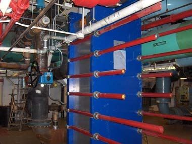
I. Introduction
The purpose of this document is to provide general guidance on the efficient use of steam. The information
contained herein is not intended to be advice or direction applicable to any specific installation. Please
consult with a licensed engineer, plumber or steamfitter for the safe and proper operation and maintenance
of your specific installation. This document is offered free of charge to current and potential customers of
the Steam Business Unit of the Consolidated Edison Company of New York. While great care has gone into
the preparation of this document, The Consolidated Edison Company of New York, Inc. does not warrant or
guarantee numbers pertaining to operational cost savings, capital cost estimates and overall project
payback.
Con Edison’s steam system is the largest district steam system of its kind in the world. Its service area
extends from the southern tip of Manhattan to 96th Street on the west side and 89th Street on the east side.
The Con Edison steam system is a considerable energy business with a customer base of over 1,700
customers.
Con Edison’s steam customers include some of the largest, world renowned buildings in Manhattan,
landmarked buildings, museums, hospitals, large apartment complexes and even small local facilities, such
as restaurants, dry cleaners, and schools. Steam customers use steam in a variety of ways including, but not
limited to:
Heating
Domestic Hot Water
Air-conditioning
Dry Cleaning
Cafeteria/Kitchen Services
Food Processing
Laboratory/Hospital Sterilization
General Cleaning
Humidification
Condensate Collection and Reuse
Snow Removal
Con Edison has historically encouraged its steam customers to undertake efficiency and conservation
efforts. For example, a free monthly seminar class on efficient steam use is available to every customer.
Furthermore, Con Edison’s website includes many steam conservation and energy efficiency tips. Recently,
because more steam customers are eligible for steam demand billing, there is a need for consumer
awareness and education concerning measures and practices that will contribute to demand reduction
along with more traditional energy efficiency measures.
In order to assist steam customers in adjusting to steam demand rates and to provide information on
energy efficiency measures, Con Edison has developed this document. The measures and technologies
presented in this Steam Best Practices Report were compiled from a number of sources including Con
Edison studies, Con Edison programs, and various equipment vendors, to provide steam customers with an
effective steam demand and efficiency management resource. Specific details regarding these studies and
programs can be found in the appendix.
For the purposes of this report, Energy Efficiency Measures (EEMs) are those measures that will reduce
overall steam consumption and, while not designed to do so, possibly the on-peak steam demand. EEMs
focus on overall efficiency and steam use reduction, and should be helpful to demand-billed and non-
Page | 5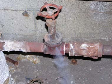
demand-billed customers alike. Demand Reduction Measures (DRMs) are those measures that will reduce
the on-peak demand, but not necessarily overall steam consumption. DRMs should be implemented solely
as on-peak steam demand management practices and are intended to help those steam customers who are
eligible for steam demand billing.

For information on the latest programs and incentives offered by Con Edison, visit our website,
http://www.coned.com/steam/. Customers who would like to supplement the information in this report
with more information on these measures or on other steam efficiency and cost optimization opportunities
may call the Con Edison Steam Business Development Group at 212-460-2011.

                                                                                                 Page | 6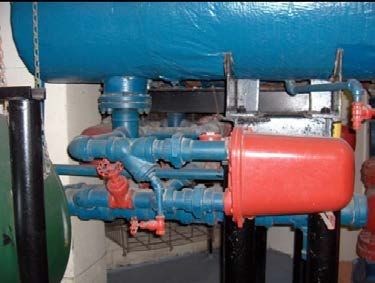
II. Reference Explanation of Demand Billing

    Demand billing was introduced to encourage Con Edison’s largest steam customers to reduce the peak
    demand on the Con Edison steam system, which typically occurs on the coldest weekday mornings (6:00
    a.m. to 11 a.m., in the winter) through rate structure that would incentivize peak management. 1 Facilities
    whose steam consumption equals or exceeds 14,000 Mlb 2 for 12 billing periods ending in August are
    subject to demand charges. Note that if the steam consumption of a demand billed customer does not
    exceed 12,000 Mlb of steam for 12 monthly billing periods ending in August of that year, the customer will
    no longer be eligible for demand billing and will be transferred to and billed under non-demand rates
    commencing with the monthly billing period that terminates within the month of November.

    Under demand billing, steam peak demand rates will only be applied during the December through March
    billing periods. Customer demand will be calculated by averaging the steam demand during the two highest
    adjacent 15-minute intervals. The demand charge will be comprised of two subcomponents – an On-Peak
    demand charge and an All-Time Peak demand charge. The On-Peak demand charge will apply on weekdays
    only, between 6:00 a.m. and 11:00 a.m. The All-Time Peak demand charge will apply to all hours during a
    given billing cycle. The All-Time and On-Peak demands will vary from month to month.

    To offset the demand charges, Con Edison has reduced the steam usage block rates for demand-billed
    customers during the four demand-billed months. Therefore, customers who have had high monthly load
    factors (monthly load factor is defined as the average demand during the month divided by the highest on-
    peak demand during the same month) or customers who are able to reduce their peak demand may see
    lower steam bills when compared to bills under the previously applicable non-demand rate. Additional
    details on the steam service tariffs can be found on the Con Edison website. 3

    By reducing the peak demand on the steam system, the need to add steam production capacity and other
    infrastructure is lessened. This helps to keep steam costs reasonable for all steam customers. It should be
    noted that there are no current capacity constraints on the steam system. The steam demand rates are
    intended to provide an incentive for consumers to modify or improve facility operations by reducing
    steam consumption during the peak steam demand period. While the techniques and technology of
    demand control and reduction for electrical consumption are well developed and are widely known to
    facility operators, the same is not true for steam demand control and reduction.

1 Demand billing was introduced in 2007 for customers using over 22,000 Mlb for 12 billing periods and was then extended to
include customers that used over 14,000 Mlb for 12 billing periods.
2 Steam is billed in Mlb. One Mlb is equal to 1,000 pounds of steam.
3 http://www.coned.com/rates/steam.asp. This address is subject to change.

                                                                                                                    Page | 7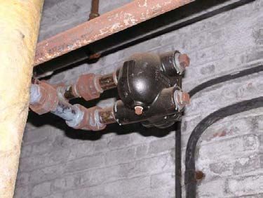
III. Economic Performance Summary

An economic performance summary of the various DRMs and EEMs discussed in this report is provided below
in Table 1 and Table 2 to inform steam customers of measures that may be applicable to their own facilities.
Table 1 displays the criteria used to determine the average ROI shown in Table 2. Economic performance and
other data for the measures presented herein was derived from specific buildings and are provided to
encourage customers to consider whether to take advantage of such measures in their facilities. Since the
applicability and performance of these measures are based on specific buildings, the Return on Investment
(ROI) information is not intended as a basis for investment decisions in other facilities. Before any investment
decision is made, a licensed professional engineer should evaluate the various options and determine their
economic feasibility.

                                           Table 1 – ROI Categories

             Average Return                   Simple                         Simple payback
             on Investment             Return on Investment                     (Years)

                Very High                 Greater than 100%                   Less than 1 year
                   High                     34% to 100%                       1.0 to 2.9 years
                Moderate                     21% to 33%                       3.0 to 4.9 years
                   Low                       20% or Less                     5 years or greater

                                     Table 2 – EEM & DRM Economics Summary
                                                           Type of Measure
                  Name of Measure                                                  Average ROI         Page #
                                                             (EEM/DRM)
All Schedule-Related DRMs                                       DRM                Very High           23-27
Reduction of Valve Hunting                                      DRM                Very High            25
Utilization of Hybrid Chiller Plants                            DRM                Very High            28
DHW Recirculation Controls                                      EEM                Very High            18
Implementation of Night Setback                                 EEM                Very High            13
Insulation of Steam Distribution Piping, Valves, and
                                                                EEM                Very High              8
Fittings
Reduction of DHW Temperatures                                   EEM               Very High              18
Steam Leak Repair                                               EEM               Very High               9
Application of the STEEMs Method                                DRM                  High                23
Condensate Heat Recovery                                        EEM                  High                16
Radiator System Optimization                                    EEM                  High                11
Reduction of Winter Operating Temperatures                      EEM                  High                13
Back-Pressure Steam Turbine Generators                          EEM               Moderate               29
Installation of a Building Management System                    EEM               Moderate               11
Utilization of a Airside Economizer                             EEM               Moderate               15
Utilization of a Waterside Economizer                           EEM               Moderate               15
Weatherization of Building Envelope                             EEM             Low - Moderate           19
Installation of Window Film                                     EEM                  Low                 19
Replacement of Low Pressure Absorption Chillers                 EEM                  Low                 15
Replacement of Single Pane Windows                              EEM                  Low                 19

                                                                                                         Page | 8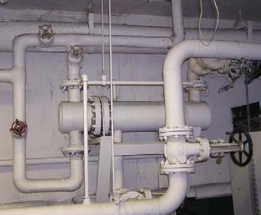
IV. Energy Efficiency Measures

  a. General Energy Efficiency Measures

       i.   Insulation of Steam Distribution Piping, Valves, and Fittings

            Piping in most buildings is generally well insulated. However, in some buildings, there are bare
            (un-insulated) pipe runs, mechanical fittings and valve bodies. This is often the case for fittings
            and valves because of the need for periodic access for service (such as traps or unions), need
            for movement (such as at valve bonnets), or because insulation was not restored after a
            component was replaced. NOTE: Insulation may contain asbestos or other hazardous fibers.
            Personnel working with insulation should be trained in proper handling methods and in the
            use of personal protective equipment.

                                                             Figure 1: Missing piping insulation.

            Un-insulated steam system components result in energy waste because they heat up generally
            unoccupied spaces and do not direct the energy to the intended end use. This heat loss could be
            avoided and delivered to the parts of the building where it is needed by installing insulation.
            Because many of these steam system components contain live steam around the clock, steam
            demand and consumption are affected.

            On un-insulated or under-insulated valves and fittings, removable insulation jackets provide a
            very useful solution to. They are ordered to specific sizes and patterns, strap into place and are
            easily removed and put back in place.

            Figure 2: Un-insulated PRV and shut-off valve.    Figure 3: Insulated valves with removable jackets.

                                                                                                          Page | 9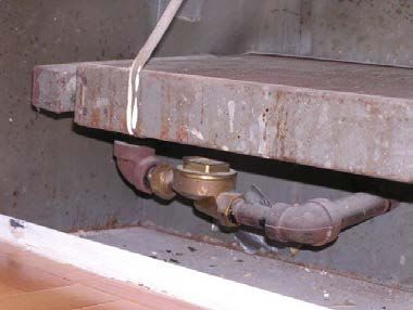
For pipes or areas that do not need to be accessed, it is recommended that insulation be
                          installed to the thickness levels shown in Table 3 below.

                              Table 3 – Recommended Fiberglass Insulation Thickness (Inches)
                                                                                                  Pipe Sizes
        Heating Piping
                                           Temperature                                                                                8"
           Systems                                                Up to         1.5" -      3" -         4" -          5" -
                                            Range (°F)                                                                               and
    (Steam and Hot Water)                                          1"           2.5"       3.75"         5"            6"
                                                                                                                                    larger
         High pressure /
                                             306-450                2.5          2.5         3           3.5            4                 4
          temperature

       Medium pressure /
                                             251-305                 2           2.5        2.5             3          3.5             3.5
         temperature

         Low pressure /
                                             201-250                1.5           2         2.5             3           3                 3
          temperature

        Low temperature                      106-200                 1            1         1.5          1.5           1.5             1.5

Source – Energy Management & Research Associates ( EMRA) recommended levels, categories from Energy Conservation Construction Code of New York
State (2002).

                          As displayed in Table 4 below, properly insulating steam piping and devices has a significant
                          impact on both energy and cost savings. Fiberglass is represented because it is most commonly
                          used. Note that there are other options available.

                                    Table 4 – Potential Annual Savings from Proper Insulation
                                  Energy Lost, Bare          Energy Lost, Insulated           Energy Savings            Annual Savings
             Size
                                       (Mlb)                         (Mlb)                        (Mlb)                     ($/ft)
                                                                Steam Piping
              12”                          18.4                           1.8                        16.6                     $515
              8”                           12.9                           1.2                        11.7                     $363
              4”                            7.1                           0.7                         6.4                     $198
                                                               Steam Gate Valves
              12”                          87.2                           8.7                        78.5                     $2,434
              8”                           58.0                           5.8                        52.2                     $1,618
              4”                           24.7                           2.5                        22.2                     $688
 Assumptions and Notes:
    1. Pipe is in service year-round (8,760 hours/year).
    2. Dollar savings based on average 2012 steam charges.
    3. Savings are based on data from US Department of Energy Steam Best Practices.

                    ii.   Steam Leak Repair

                          Steam leaks are a source of significant energy loss. Leaks are most often found at pipe
                          junctions, fittings, or in valves. The leaks may be due to leaking gaskets, loose connections, or
                          pinholes. It is hard to measure the size of a leak and the extent of steam loss. For basic safety

                                                                                                                              Page | 10
and economic reasons, all leaks should be addressed immediately. On occasion, leaks in valves
may require that the valves be replaced.
Figure 4: Investing the capital to fix visible Figure 5: Relief valve leaks are usually overlooked,
steam leaks typically results in a high ROI. but can result in significant increases in steam
consumption.
As displayed in Table 5 below, repairing steam leaks properly and in a timely manner has a
large impact on both energy and cost savings.
Table 5 – Potential Annual Savings from Steam Leak Repair
Leak Hole Consumption Demand Annual
Steam loss
Pressure Size Savings Savings Savings
(lb/hr)
(PSI) (inches) (Mlb) (Mlb/hr) ($)
165 1/16 22 188.5 0.022 $5,844
165 1/8 86 754.1 0.086 $23,377
45 1/16 6 52.6 0.006 $1,631
45 1/8 23 201.5 0.023 $6,247
15 1/16 2 17.5 0.002 $543
15 1/8 8 70.1 0.008 $2,173
Assumptions and Notes:
1. Leaking pipe/fitting is in service year-round (8,760 hours/year)
2. Dollar savings based on energy and demand charges for a mid-sized commercial office building
3. Dollar savings based on average 2012 steam rates.
4. Source of Consumption savings data: CIBO ENERGY EFFICIENCY HANDBOOK, Copyright 1997 Council of Industrial Boiler Owners.
Derived from Table 10-1.
Page | 11b. Heating Distribution Energy Efficiency Measures
i. Installation of a Building Management System
In facilities where a Building Management System (BMS) does not currently exist, there are a
number of benefits that can be accrued by installing a computerized BMS. Note that a BMS is
sometimes referred to as an Energy Management System (or EMS). While a BMS can be costly,
it is a valuable tool that can yield significant returns. To optimize such an investment, it is very
important that the operators are trained to review, understand, and act upon the information
that such a BMS or EMS can provide.
Savings from the installation of a well-designed and maintained BMS will come from a number
of areas including the following:
Personnel cost optimization; reduced time requirements for “rounds” enable
personnel to respond to complaints and conduct other activities such as maintenance;
Essential support for the implementation of other steam DRMs/EEMs:
Accurate control and feedback on space and/or air handling unit (AHU) supply and
return temperatures;
Greater control and ability to meet the requirements of various areas of the facility and
to respond to occupant comfort complaints;
Reduction/elimination of space overheating; the reduction of system “lag” time
Trending of various key parameters to identify equipment issues and system
inefficiencies; identification of conditions, practices, and equipment that are resulting
in less than optimal energy utilization or may require maintenance and replacement;
Improved utilization of water to cool condensate through monitoring and control of
cooling water control valve based on condensate temperature; and
Documentation of conditions for occupant complaint response/resolution.
If installing a BMS is not economical, at a minimum, facility personnel should manually fill out
logs that include information such as steam pressures, space temperatures, outside
temperatures, zone valve openings, vacuum readings, return water temperatures, domestic hot
water (DHW) temperatures, etc. Spreadsheets could be developed to track the above data and
identify operational trends and spot issues before they become significant energy wasting
and/or equipment failure problems.
ii. Radiator System Optimization
Steam heating is used inefficiently in many buildings—both commercial and residential—due
to a lack of localized control. This is especially true in older buildings where the occupants have
modified the space layout but the distribution systems have remained as originally designed,
which can result in overheating or under-heating. Units in more modern buildings are treated
as multiple zones, with each unit being able to control the local space temperature. In contrast,
older buildings often heat their spaces as one zone. This approach leads to inefficient building
heating since parts of the building get warmer or cooler at different rates. If the temperatures
of these cooler areas are below a certain minimum temperature, the entire building is heated
since it is treated as one zone. As a result, the remaining areas of the building become too
warm. This overheating prompts residents to waste energy by opening windows and/or
turning on air conditioning units during the heating season.
Page | 12Figure 6: Steam Radiator.
Below are some of the many options available to prevent a radiator from overheating a space:
1) Clear any objects on or near radiators:
During warmer seasons, radiators are sometimes used as shelves as objects are placed
and/or stored on radiators. When not cleared, these objects may block heat energy
from reaching outer areas of a room, resulting in extra steam being used in order to
compensate for this hindrance. These objects should be cleared by the start of the
heating season to prevent unnecessary energy losses.
2) Install Thermostatic Radiator Valves:
Thermostatic Radiator Valves (TRVs) provide individual zoning control at the radiator
level, allowing the occupant to select and set different temperature set points to meet
an individual comfort level. Since the valve operation is controlled by the thermostatic
element within the valve, once the settings are selected and set, there is no need to
manually open and close the steam supply valve to control temperature. The
installation of these valves in overheated areas prevents discomfort and provides
significant savings. In buildings with large southern exposure or on higher floors,
installation of TRVs in these areas will help minimize overheating and help balance the
building’s heating system. These valves can be linked to a remote thermostat or BMS
control for optimal control.
Figure 7: Thermostatic radiator valve.
3) Adjust controls to more appropriate settings for the building:
For buildings employing a two pipe VariVac steam distribution system (with MEPCO
DCC-1000 control panels, or similar devices from other manufacturers), the control
panels operate as an outdoor reset control which varies the steam supply valve
opening based on the outside temperature and temperature feedback from the
condensate return system. To reduce overheating, the compensator on the panel
should be adjusted to a more appropriate setting for the building.
Page | 13For buildings employing two pipe steam distribution systems with Heat Timer®
control panels, or similar devices from other manufacturers:
Reset Heat Adjustment (Alpha setting) on the Heat Timer® Panel. The exact
setting should be determined by a series of lowering and observational tests
(survey of space temperatures) conducted by facilities staff.
Reset the Heating System Sensor (XYZ knob) to a lower temperature so that
the heat timer senses that distribution has been established and the cycle
clock has begun. There may also be a need to relocate the sensor to a more
appropriate location based on the distribution characteristics of the space.
Check the Heat Timer® manual for proper sensor location.
Institute an occupant/staff educational program, to be carried out either with
direct flyers distributed as paycheck stuffers, (or to tenants in rent bills),
through the company intranet and email systems, and/or bulletins posted in
elevators. Tenants should be advised by building management that radiators
can and should be turned down or shut off with a valve when a room becomes
too warm (rather than opening windows or turning on air conditioners).
iii. Implementation of Night Setback
In buildings where the temperature settings remain constant around the clock, it is advisable to
institute a night setback. To avoid larger than necessary demand charges, it is suggested that
the setback operation last from either the end of the business day (in office buildings), or from
10:00 p.m. (in multifamily buildings) through about 4:00 a.m. Ending setback operation no
later than 4:00 a.m. will give the demand-billed buildings enough time to heat up before the
peak demand period of 6:00 a.m. to 11:00 a.m.
iv. Installation of Programmable Clock Thermostats
In spaces such as restaurants, professional offices and other storefronts that operate
independently from main distribution systems, a programmable clock thermostat should be
installed on the local heating system. Given that the normal operating hours of such spaces
begin during the peak demand period and the normal procedure is to manually switch the
system on at that hour, these spaces contribute to the facility’s peak demand. The start-up
times and early morning settings of such thermostats should be coordinated with the
operations of the main building zones to reduce peak demand. In some cases, as determined
from experimentation in the facility, it may be more cost effective to preheat these spaces
before the 6:00 a.m. start of the on-peak demand period.
v. Reduction of Winter Operating Temperatures
In facilities that have core/perimeter heating and domestic hot water systems, it is possible to
reduce equipment temperature set points either during the on-peak demand period or
throughout the day without impacting occupant comfort. Often, these systems are programmed
at higher settings than required, and a facility may find that these settings can be lowered
permanently without affecting comfort conditions. This measure could be applied to domestic
hot water heaters, heat exchangers, and AHUs. By reducing these set points by just a few
degrees, facilities can reduce their total steam consumption as well as their steam peak during
the demand period.
Page | 14vi. Utilization of Rejected Heat
A facility should investigate the feasibility of allowing data centers and other continuous heat
sources to discharge heated air to the return plenums to offset the requirement for steam
during the heating season. Based on the building design, this strategy could be done naturally
or could be introduced.
vii. Demand Control Ventilation
Currently, most buildings are designed to provide the minimum required outside air based on
the maximum occupancy for each space. Demand Control Ventilation is a method of reducing
the minimum outside air requirements of a space based on real-time occupancy as opposed to
the maximum occupancy for the space. This can be accomplished by using sensors, such as CO2
sensors, to measure the carbon dioxide concentration within a space. Based on this data, actual
occupancy can be determined and ventilation rates can be adjusted appropriately. By
minimizing outside air intake to the required minimum based on actual occupancy and
recirculating more return air, steam consumption will be lowered.
Page | 15c. Steam Air Conditioning Energy Efficiency Measures
i. Raise Summer Operating Temperatures
In facilities that have centralized air conditioning systems, it is possible to increase equipment
temperature set points throughout the day without impacting occupant comfort. This measure
could be applied to chillers and AHUs. By increasing these set points by just a few degrees,
facilities can reduce their total steam consumption.
ii. Utilization of a Waterside Economizer
During winter and shoulder months, in facilities where air conditioning is still required, a
waterside economizer can be used in lieu of a chiller to provide cooling. By routing condenser
water from the cooling tower through a heat exchanger, chilled water can be produced due to
the low outside air temperature. This is also referred to as “free cooling.” Installing a plate and
frame heat exchanger for free cooling will save on energy costs by minimizing chiller operation.
Figure 8: Plate and Frame Heat
Exchanger.
iii. Utilization of an Airside Economizer
During winter and shoulder months, in facilities where air conditioning is still required, an
airside economizer can be used in lieu of a chiller to provide cooling. By modulating outside air
dampers, cool outside air is allowed to enter AHUs instead of conditioned return air. If outside
air temperatures are lower than what is required by the building, return air can be mixed with
the outside air to reach the temperature set points. Using this type of “free cooling,” the
building cooling loads can be met without using chillers and this function can be automated in
facilities equipped with a BMS. To accommodate free cooling, the outside air dampers would
need to be sized for full air flow.
iv. Replacement of Low Pressure Absorption Chillers
In buildings that utilize low pressure steam absorption chillers, it is possible to replace these
units with high pressure steam absorption chillers that use almost 50% less steam. In cases
where a facility operates on one chiller with the other as backup, only one of the chillers needs
to be replaced to attain the majority of the potential EEM benefits. The new chiller would
become the primary unit with the remaining low pressure chiller available as backup. Note that
depending on the location of the mechanical rooms that house the chiller, new high pressure
steam supply lines may have to be installed to operate the high pressure chillers. New pressure
reducing stations may be required if the high pressure riser replaces the low pressure riser.
Page | 16v. Insulation of Chilled Water Distribution Piping, Valves, and Fittings
All chilled water equipment should be properly insulated. This includes but is not limited to:
chiller evaporator sections, piping, fittings, and pumps. If a waterside economizer is used for
free cooling, all condenser water components should be insulated as well. Refer to the
Insulation of Steam Distribution Piping, Valves, and Fittings section under General Energy
Efficiency Measures for more information.
Page | 17d. Condensate Management
Before implementing condensate management measures, a customer should consult with a competent
water treatment vendor or another qualified professional to implement a water treatment plan and/or
system design specifications in order to minimize the long-term risks of corrosion and fouling. For
reference, condensate management illustrations have been included in the appendix.
In most facilities, hot steam condensate return is collected at approximately 180°F and is tempered
with city water before being discharged into the sewer. The discharged condensate must be at a
temperature less than 150°F for compliance with DEP requirements and the New York City plumbing
code. 4 By doing so, facilities are not only wasting the purchased thermal energy in the condensate but
also the city water used to cool it. To avoid this, condensate can be used in a variety of ways.
i. Condensate Heat Recovery
Hot steam condensate return can be used for preheating. In locations where the condensate
return is near an existing thermal load and space for the equipment exists, a heat exchanger
can be installed to recover the heat from the condensate to preheat incoming domestic water.
The hot condensate can also be used for outside air preheating by routing the condensate
through coils located in the fresh air intake.
Hot steam condensate can also be used for heating by using the condensate in a hydronic loop.
In facilities that have a steam distribution system, the first few floors of a building can be
converted to a hydronic system to take advantage of this measure.
These strategies reduce the temperature of the condensate, reduce or eliminate the need for
quenching water and reduce steam consumption.
Figure 9: A condensate heat recovery
system with a shell and tube heat
exchanger.
4
http://www.nyc.gov/html/dob/downloads/pdf/plumbing_code.pdf. This address is subject to change.
Page | 18Figure 10: A condensate heat recovery system
with a storage tank.
ii. Condensate Reuse
As an alternative to draining condensate water, steam condensate can be reused as greywater
for any purpose that does not require potable water.
Below are some greywater uses for condensate:
Cooling tower water make-up
Supply water for outdoor fountains
Toilet water
Water to wash sidewalks
Dishwasher/Laundry supply for hotels and restaurants
Irrigation water for landscape and gardens
To implement some of these methods, the condensate may still need to be tempered with city
water prior to reuse. These strategies reduce the amount of city water purchased by a facility
and are best if used in conjunction with thermal heat recovery.
Figure 11: To maximize resource recovery,
condensate can be used for cooling tower
make-up after its heat has been recovered.
When using the condensate for cooling tower make-up, facilities should confirm if the make-up
water for the cooling tower is being included on their sewer charges. If so, a sub-meter could be
installed to monitor the amount of cooling tower make-up water. This make-up water quantity
can then be deducted from a facility’s sewer charges.
Page | 19e. Domestic Hot Water (DHW) Energy Efficiency Measures
i. DHW Recirculation Controls
It is not necessary to run DHW recirculation pumps continuously, which circulate hot water
through the pipes around buildings at 130°F - 140°F. Installing and setting a reverse acting
aquastat on the return line will reduce the amount of energy used to provide hot water while
retaining the quality of the hot water expected by the occupants. Additionally, there will be
some electrical cost savings from the reduced run time on the pumps. The aquastat should be
installed a few feet upstream of the pump inlet and set at 110°F, with the deadband set at +/-
5°F, and wired into the domestic hot water circulation pump in the building. 5 In some
buildings, return line aquastats have already been installed, but are set so high that the pumps
are running continuously. The aquastat would need to be reset as described above.
ii. Reduction of DHW Temperatures
In some buildings, the DHW temperature is too hot, often at an average above 130°F. Note that
in multifamily buildings, the New York City housing maintenance code requires delivery of
120°F water to taps. The overheating of this water not only wastes steam, but is also a
potentially dangerous situation. Hot water at 132°F will scald human skin. The DHW delivery
temperature should be adjusted so that it delivers 120°F water to the spaces with taps that are
furthest from the mechanical room. This will take some trial and error, as design of piping
systems varies, but the temperature of DHW leaving the mechanical room should be
somewhere between 125°F and 140°F, depending on the size and configuration of the building.
5
Goldner, F.S.. DHW Recirculation System Control Strategies, Final Report 99-1. Prepared for New York State Energy Research and
Development Authority. Prepared by Energy Management & Research Associates. January 1999.
Page | 20f. Building Envelope
i. Weatherization of Building Envelope
Windows at some sites are in poor condition, which allows for water and air penetration.
Weather-stripping and caulking these windows will minimize air infiltration and heat loss
while providing energy savings and greater comfort to building occupants. Similarly, all
building exterior doors, specifically main entrances, service entrances, and roof doors, should
have weather-stripping and door sweeps installed. Walls and roofs should also be properly
insulated to effectively retain energy in the winter and the summer.
Figure 12: Poor building envelope maintenance,
as exemplified by this missing AC sleeve cover,
contribute to increased energy consumption.
ii. Installation of Window Film
A facility’s varying exposures can contribute to imbalances in heating and cooling. Solar gains
can be especially troublesome for cooling. Reflective window film technology has advanced
significantly and can be applied to create greater shading coefficients to reduce unwanted solar
loads. Facades that have heavy morning solar loads should be considered for treatment with
high reflectivity window film.
iii. Replacement of Single Pane Windows
Buildings with the original single pane windows still in place should consider replacing them
with more energy efficient windows. Double pane windows are insulated, which helps to retain
heat in the winter and air conditioning in the summer. Therefore, energy costs will be reduced
while occupant comfort is increased.
Page | 21g. Facility Maintenance and Management Practices
i. Integration of Steam Demand Meter Data into BMS
Pulse signals from steam demand meters can be utilized through a facility’s BMS to allow
building personnel to have a real time display of the building’s steam demand. A graphic
representation of steam demand data can be a valuable tool for identifying equipment and
practices that are resulting in high steam demand and consumption. In addition, the storage of
demand data for later analysis will support tracking the effectiveness of EEM or DRM
implementation.
Facilities that are interested in obtaining demand data should contact the Steam Business
Development Group at (212) 460-2011. In order to participate, the facility will need to submit a
completed Program Agreement that will be provided upon request. The installation of isolation
relays will need to be completed as per Con Edison Specification S-671 below. Then, an
inspection of the completed installation and tie-in to Con Edison’s flow computers will need to
be scheduled by calling 1-800-75-CONED.
Figure 13: Con Edison Specification S-671- Installation of Isolation Relays.
ii. Steam Trap Inspection and Maintenance
Steam traps perform the critical function of removing condensate from steam pipes. When
traps are not operating properly, condensate can accumulate in the steam pipe and a condition
known as water hammer can occur. Severe water hammer can cause steam pipes or fittings to
Page | 22fail, causing serious property damage and personal injury. Improperly working steam traps can
also lead to steam balancing problems, resulting in occupant discomfort. A trap that fails in the
open position wastes energy, increases costs, and can cause high indoor temperatures.
To ensure safe and reliable steam system operation, steam traps and other condensate-removal
equipment should be inspected regularly to make sure they are working properly. Each
radiator located throughout a building should have the steam trap thermostatic element, or
“disk” and the trap seat checked for need of replacement as recommended by the trap
manufacturer. A program of inspection and repair/replacement of non-working steam traps
will increase both overall operating efficiency and occupant comfort.
Figure 14: Radiator steam traps, such as this one, should
be inspected at intervals recommended by the manufacturer.
Most buildings do not have a direct indication of steam trap blow-through. As live steam blows
through traps, the temperature of the returning condensate will increase. The temperature
of the condensate entering a dilution tank and the volume of the water added are both
instrumentation points that provide good indications of steam trap performance. These
instrumentation points can be added to a facility’s BMS for trending, and operating staff should
be trained how to interpret the data.
Figures 15 & 16: Main steam traps should be inspected as often as is recommended by
the trap manufacturer.
There are various services available to assist facilities in the inspection and maintenance of
their steam traps. Remote trap monitoring systems can be installed to automatically monitor
traps for failure. These systems can also be linked to a facility’s existing BMS. Outside
contractor services are also available to survey steam systems and perform maintenance on
traps regularly.
Page | 23iii. Expansion Joint Replacement
In buildings over 30 years of age, all expansion joints should be replaced. After this period of
time, it should be expected that these joints are at the end of their expected useful life and
either have or will begin to fail, creating leaks in the steam heating distribution system. In
vacuum steam distribution systems, the system’s ability to pull a proper vacuum is lowered as
a result of leaks. It is recommended that these joints be removed and replaced with piping
loops. By replacing expansion joint proactively, the efficiency of vacuum as well as gravity drain
steam systems will be optimized.
iv. Installation of Sub-Metering
In some facilities, there are tenants that use chilled water, hot water, and DHW from the main
building and do not pay directly for their utility use. By installing their own demand and
consumption meters for these end users, facilities can fairly assess the tenants’ individual use.
These meters will serve two purposes. First, they will provide accurate records for invoicing
steam usage to the shareholders based on their actual usage. Second, this data will provide the
necessary measurement information on demand and consumption, which can be used by
facilities to develop future energy conservation measures to reduce both steam demand and
consumption.
v. Establishment of a “Green” Policy for Hotels
Hotels should provide in-room notification suggesting that all guests turn down terminal
heating/cooling units upon leaving their rooms and re-use towels if possible. Housekeeping
staff should be notified to turn off lights and terminal units after servicing rooms.
Page | 24V. Demand Reduction Measures
Note: STEEMs is a patent technique
a. Heating Distribution Demand Reduction Measures
(patent #8955763)
i. Application of the STEEMs Method
The Storage of Thermal Energy in Existing Mechanical Systems (STEEMs) is a steam demand
reduction strategy developed by Con Edison for the benefit of demand-billed steam
customers. The main element of this strategy involves using a BMS or a special-purpose
controller to heat a circulating hot water loop to a higher temperature during unoccupied night
hours and using the heat energy stored in the loop to displace steam consumption during the
morning start-up. See the Appendix section for more detailed information about this strategy.
A building is a good candidate for implementing STEEMs if it meets all of the following criteria:
It uses circulating hot water for a significant portion of its space heating.
Each of its terminal heating units (e.g. induction units, fan coil units, and fan powered
boxes) has a local thermostatically controlled valve to avoid space overheating.
It has a programmable BMS. In the absence of a BMS, a special-purpose controller is
required.
Two STEEMs techniques have been developed:
STEEMs Using Dynamic Response, which require a building steam flow rate signal for
feedback. Although this strategy is more difficult to program than STEEMs Using
Scheduled Reset (see below), the potential for steam demand reduction using this
technique is higher. Furthermore, the water temperature control valves need to be
tuned to minimize steam flow rate fluctuations during the STEEMs mode of
operation.
STEEMs Using Scheduled Reset does not require building steam flow rate signal
for feedback. It is simpler to program than STEEMs Using Dynamic Response (see
above). However, after the programming is complete, it requires experimentation by
building engineers to identify an operating configuration that will maximize the
amount of on-peak demand reduction. Furthermore, the water temperature control
valves need to be tuned to minimize water temperature overshoot and undershoot.
Implementing STEEMs will not necessarily reduce the total amount of steam usage. STEEMs
operation will shift when steam is used and result in shaving the steam peak and reducing
associated demand costs. Detailed implementation tips are included in the Appendix.
ii. Steam Load Shifting
There are a number of steam demand shifting strategies for facilities to consider. These
strategies include:
1) Preheating the building prior to the demand billed period:
By raising heating and hot water temperature set points prior to the peak steam
demand period (6:00 a.m.), a facility can meet or slightly exceed space requirements
prior to the demand period and then reduce the set points from 6:00 a.m. to 11:00 a.m.
Page | 25Some building tenants, such as restaurants, open in mid-morning, meaning that their
heating systems will start establishing comfortable temperatures during the peak
steam period. Pre-heating these spaces before the steam peak or through coordination
with other systems based on steam demand (through BMS or local controls) may
moderate the demand charges associated with the subject area’s heating.
2) Reducing the heat to non-critical areas:
Reducing the heat to spaces where heating is not critical, such as loading docks or
garages, during the peak steam demand period will reduce the facility’s on-peak
demand. Facilities with occupant amenities, such as pools and gyms, can also restrict
heating to these areas during the peak demand period.
Figure 17: Minimizing the use of
non-essential heating, such as this
garage heater, during the on-peak
period will help reduce demand.
In facilities where there are steam process loads, delaying some or all of the process
loads until after the steam peak demand period can reduce demand. As an example,
this could be applied to hotels that have on-premises laundries. If possible, laundry
operations should be delayed until after 11:00 a.m., or units should be sequenced to
avoid the aggregation of coincident loads for a high peak demand. This will help reduce
peak steam demand charges.
To the extent possible, these measures should be implemented through automatic scheduling
in a BMS, with input from the customer’s steam demand meters to determine the level of pre-
heating or heat reduction during the steam peak demand period.
iii. Adjustment of Air Handling Unit Schedules in a BMS
In many facilities, the AHU schedules in the BMS were observed to change operating mode to
Startup or Occupied mode and operate the AHUs all at the same time or close to 6:00 a.m.,
which is the beginning of the peak demand period. This mode of operation could cause an
unnecessary peak during the demand period. These schedules can be adjusted to stagger the
mode change, which will reduce the possibility of a demand peak occurring when these units
start all at once and call for heat.
Page | 26Figure 18: Starting up air handling units
before 6:00 a.m. or staggering their start-up
will reduce the on-peak demand.
A recommended procedure is to only start up early those AHUs that serve the spaces that get
the coldest overnight. Starting up all the AHUs earlier, including those that serve spaces that
remain warm through the night, may not be justified due to a more significant increase in
electric charges. Alternatively, if the AHUs are already running, set point temperatures should
be raised to preheat the building prior to peak hours. From 6:00 a.m. to 11:00 a.m., the set
point can be reduced to normal, minimizing steam demand charges.
iv. Reduction of Valve Hunting
Figure 19 shows a typical steam demand profile for a facility in which valve “hunting” is taking
place. Hunting, shown by the “sawtooth” pattern of demand oscillation, is often a symptom of a
control system requiring coordination adjustment between the control device (e.g. a steam
pressure regulator or a water temperature control valve) and the controlling point within the
system. Hunting will result in accelerated wear and shortened service lives for components
such as the temperature control and pressure reducing valves, as well as steam turbine nozzle
controls and linkages if this also occurs during the cooling season.
In addition to the impact on control equipment service life, hunting may result in the peak
steam demand being higher than necessary each month. The short, sharp peaks that result
from hunting may induce higher recorded demand. A sample of the hunting induced higher
peak versus the peak demand estimated from reduced hunting is presented in Figure 20. Actual
demand reduction achieved by reducing or eliminating the hunting will depend on the cause
and the degree to which the hunting can be smoothed. However, in buildings with BMS
systems, this should be a very low cost DRM to implement.
Page | 27Figure 19: Steam Control Valve Hunting Profile.
Figure 20: Hunting Demand vs. Estimated Average Demand.
v. Zone Valve Sequencing and Scheduling
In facilities equipped with heating distribution systems that employ zones and zone controls,
the operation and scheduling of the zones should be such that they do not simultaneously
commence operation, imposing a large spike in steam demand during the steam demand billing
period. This concept is the same as the staging of electrical loads such as chillers. In facilities
with multiple zones, schedules should be set up so that no more than half of those valves are
allowed to be open concurrently during the peak demand period. The figure below illustrates
the spike caused at a multifamily complex due to simultaneous start-up of all the zone heating
systems.
Page | 28Figure 21: Multiple Zone Induced Peak Demand.
Page | 29b. Steam Air Conditioning
i. Utilization of Hybrid Chiller Plants
By installing a chiller plant that contains both electric-driven and steam-driven chillers,
facilities are able to select the commodity that provides the most economical operation. During
winter billing periods, steam demand rates are present and chillers are most likely running at
part load. Therefore, operating electric chillers is more cost efficient. During summer electric
peak periods, when electric demand rates are higher, it is more cost-effective to use steam
chillers.
ii. Steam Load Shifting
Facilities with areas that require air conditioning during the winter billing periods should
consider precooling these areas prior to the demand billed period. By lowering the
temperature set points prior to the peak steam demand period (6:00 a.m.), a facility can meet
or slightly exceed space requirements prior to the demand period and then reduce the set
points from 6:00 a.m. to 11:00 a.m.
Page | 30VI. New Technologies in Energy Efficiency
The following material is provided as an informational source only. The publication or sharing of this
information should not be considered, in any way, to be an endorsement, recommendation or promotion,
either expressed or implied, of any of the technologies listed thereon. Accordingly, it is the customer’s sole
responsibility to investigate and determine the technical capabilities and reliability of the technologies
prior to entering into a contract for services provided by these products. This list is not intended to be an
all-inclusive list of qualified technologies.
i. Back-Pressure Steam Turbine Generators
Con Edison steam enters customers’ locations at approximately 140 psig – 180 psig. In most
buildings, the pressure of the incoming steam must be reduced prior to being distributed
throughout the facility. For customers using steam for heating, DHW, and/or low pressure air
conditioning, the required steam pressures are no more than 30 psig. Typically, facilities use
pressure reducing valves to step down the steam pressure. Appropriately sized steam turbine
electric generators are available that can be used for steam pressure reduction in parallel with
pressure reduction valves. These units use incoming high-pressure steam to produce electricity
and output low-pressure steam. By installing this technology, the energy consumed in the
pressure reduction can be used to provide some electric cost savings with no impact to a
facility’s steam system. Small units are capable of producing approximately 100 kW of electric
power when operated using a minimum steam load of 3.0 Mlb/hr and a maximum steam load
of 5.0 Mlb/hr. Preliminary analysis indicates that a customer location with a base load of 3.0
Mlb/hr for between 1,900 hours to 3,200 hours per year would achieve a simple payback of 3-5
years. Larger units that produce 250 kW of electric power would require over 12.0 Mlb/hr base
loads and may be harder to justify for most buildings.
ii. Fully-integrating Steam Chiller Control Systems
Control systems that fully integrate BMS controls with steam turbine chillers are available to
increase the efficiency of these units. Since the control system automatically monitors all
major components of the steam chiller, steam usage can be optimized and reduced
significantly. Steam customers have seen reductions anywhere from 5% to 32% in their steam
energy usage upon installation of such control systems, with a simple payback period within
one to three years in most cases.
These control systems help reduce the amount of steam needed to run existing chillers by:
1) Compressor Pre-Swirl Optimization:
Reducing the entering condenser water temperature (ECWT) when reducing
chiller load to permit head relief to the compressor
Allowing for sloping and de-rating of turbine drive to reduce overall
consumption
Maintaining the fluidity of gases within the chiller to reduce resistance
2) Nozzle Optimization Control
Reducing the volume of steam needed to operate turbines
3) Vacuum Distillation and Filtration of Turbine Oil
Maintaining efficiency of turbine by eliminating foreign matter from the
turbine oil
Page | 31You can also read