Optimization of the fused deposition modelingbased fabrication process for polylactic acid microneedles - Nature
←
→
Page content transcription
If your browser does not render page correctly, please read the page content below
Wu et al. Microsystems & Nanoengineering (2021)7:58
                                    https://doi.org/10.1038/s41378-021-00284-9
                                                                                                                                                               Microsystems & Nanoengineering
                                                                                                                                                                                                www.nature.com/micronano

                                     ARTICLE                                                                                                                                                    Open Access

                                    Optimization of the fused deposition modeling-
                                    based fabrication process for polylactic acid
                                    microneedles
                                                                                                                                              1✉
                                    Libo Wu1, Jongho Park                     1
                                                                               , Yuto Kamaki1 and Beomjoon Kim

                                      Abstract
                                      A microneedle (MN) array is a novel biomedical device adopted in medical applications to pierce through the stratum
                                      corneum while targeting the viable epidermis and dermis layers of the skin. Owing to their micron-scale dimensions,
                                      MNs can minimize stimulations of the sensory nerve fibers in the dermis layer. For medical applications, such as wound
                                      healing, biosensing, and drug delivery, the structure of MNs significantly influences their mechanical properties.
                                      Among the various microfabrication methods for MNs, fused deposition modeling (FDM), a commercial 3D printing
                                      method, shows potential in terms of the biocompatibility of the printed material (polylactic acid (PLA)) and
                                      preprogrammable arbitrary shapes. Owing to the current limitations of FDM printer resolution, conventional micron-
                                      scale MN structures cannot be fabricated without a post-fabrication process. Hydrolysis in an alkaline solution is a
                                      feasible approach for reducing the size of PLA needles printed via FDM. Moreover, weak bonding between PLA layers
                                      during additive manufacturing triggers the detachment of PLA needles before etching to the expected sizes.
                                      Furthermore, various parameters for the fabrication of PLA MNs with FDM have yet to be sufficiently optimized. In this
                  1234567890():,;
1234567890():,;
                  1234567890():,;
1234567890():,;

                                      study, the thermal parameters of the FDM printing process, including the nozzle and printing stage temperatures,
                                      were investigated to bolster the interfacial bonding between PLA layers. Reinforced bonding was demonstrated to
                                      address the detachment challenges faced by PLA MNs during the chemical etching process. Furthermore, chemical
                                      etching parameters, including the etchant concentration, environmental temperature, and stirring speed of the
                                      etchant, were studied to determine the optimal etching ratio. To develop a universal methodology for the batch
                                      fabrication of biodegradable MNs, this study is expected to optimize the conditions of the FDM-based fabrication
                                      process. Additive manufacturing was employed to produce MNs with preprogrammed structures. Inclined MNs were
                                      successfully fabricated by FDM printing with chemical etching. This geometrical structure can be adopted to enhance
                                      adhesion to the skin layer. Our study provides a useful method for fabricating MN structures for various biomedical
                                      applications.

                                    Introduction                                                                                        applications of MNs have been further developed for
                                      A commercially available microneedle (MN) patch is                                                wound healing and biosensing2–4. MNs can bypass the
                                    primarily a cosmetic product that contains micron-sized                                             stratum corneum, which is the outermost barrier layer of
                                    polymer needles. The concept of MNs was first intro-                                                 the skin. Active pharmaceutical ingredients (APIs) are
                                    duced in 1976 for transdermal drug delivery1. Biomedical                                            subsequently administered to the viable epidermis and
                                                                                                                                        dermis layers of the skin. MN-mediated applications
                                                                                                                                        enable delivered APIs to block abnormal cell cycles in the
                                    Correspondence: Beomjoon Kim (bjoonkim@iis.u-tokyo.ac.jp)
                                    1
                                                                                                                                        skin, which can treat lesions5. Compared with the sys-
                                     Institute of Industrial Science, The University of Tokyo, 4-6-1 Komaba, Meguro-
                                                                                                                                        temic drug delivery method, drug delivery by MNs tar-
                                    ku, Tokyo 153-8505, Japan
                                    These authors contributed equally: Libo Wu, Jongho Park, Yuto Kamaki,                               geting affected dermal cells can improve the efficiency of
                                    Beomjoon Kim

                                    © The Author(s) 2021
                                                        Open Access This article is licensed under a Creative Commons Attribution 4.0 International License, which permits use, sharing, adaptation, distribution and reproduction
                                                        in any medium or format, as long as you give appropriate credit to the original author(s) and the source, provide a link to the Creative Commons license, and indicate if
                                    changes were made. The images or other third party material in this article are included in the article’s Creative Commons license, unless indicated otherwise in a credit line to the material. If
                                    material is not included in the article’s Creative Commons license and your intended use is not permitted by statutory regulation or exceeds the permitted use, you will need to obtain
                                    permission directly from the copyright holder. To view a copy of this license, visit http://creativecommons.org/licenses/by/4.0/.
Wu et al. Microsystems & Nanoengineering (2021)7:58                                                                                                               Page 2 of 13

                                                                                             OH-
                                                                                       CH3                          CH3         O                 CH3         O
                                                                                                       H2O
                                                                                             O                            O                             O
                                                                                   O                            O                       OH + HO
                                                                                                 n                            x                             y
                                                                                         O       CH3                  O       CH3                   O       CH3
                            PLA filament                    Welding of interface
                                                                                                             Hydrolysis of PLA
                        Z
                                            Rotating gear
                               Y

                   X
                                                                         b                                                          c
                       Printing nozzle
                                             Molten PLA
                  PLA needle array

                  Printing stage

                                    a
                                                                         d                                                          e
 Fig. 1 Illustration of PLA MNs fabricated by combining FDM and chemical etching. a PLA needle arrays with predesigned structures printed by
 FDM. b PLA needle arrays printed under the optimized condition to form optimal welding at the interfaces of successive layers. c PLA needles
 chemically etched via the hydrolysis of PLA under alkaline conditions. d PLA MN array obtained after chemical etching. e PLA MNs coated with API

drug administration and eliminate drug side effects6. The                       DLP and SLA methodologies have been adopted to
physical stimulation of epithelial and endothelial cells in                  fabricate photopolymer MNs with high resolution12,13.
wounded areas has been demonstrated to induce the                            The potential skin sensitization triggered by the photo-
genetic expression of growth factors, which facilitate                       polymers used in DLP and SLA is non-negligible. The
wound healing7.                                                              safety of the photopolymers in DLP and SLA may require
  There has been increasing interest in MN-mediated                          further validation via clinical tests. In contrast, FDM is a
biosensing. The targets of MN-mediated biosensing are                        commercial AM method that melts thermoplastics into
blood or interstitial fluid (ISF). ISF in the epidermis is a                  the molten state, in which objects are fabricated using a
source of several biomarkers, such as ions, proteins,                        layer-by-layer approach (Fig. 1a). A significant advantage
metabolites, and glucose. MNs can be used to painlessly                      of the FDM-based method for MNs is that polylactic acid
collect biomarkers from ISFs in the epidermis. Biosen-                       (PLA) can be used to fabricate PLA needle arrays. PLA is a
sing platforms that significantly minimize the invasive-                      Food and Drug Administration-approved biocompatible
ness of the detection of several analytes have been                          material for the application of bone implants, sutures,
considered for various MN-based diagnoses8.                                  sustained drug delivery, and vaccine antigens14. High
  Various MN fabrication methods have been resear-                           molecular weight PLA can be degraded into low mole-
ched, such as molding methods and drawing litho-                             cular weight PLA and biodegradable lactic acid via ester
graphy9,10. Among them, molding is the most                                  linkage hydrolysis in vivo15. Accordingly, PLA is con-
conventionally adopted fabrication method for polymer                        sidered safe for use as an MN material. Furthermore,
MNs. However, demolding MNs from negative molds                              disposal methods for PLA objects include composting,
can potentially destroy the structures of MNs. Wearable                      chemical recycling, and mechanical recycling16.
biomedical applications of MNs have been considered,                            The printing resolution of the conventional FDM pro-
and the geometrical structures of MNs have been                              cess cannot produce MNs with a tip diameter of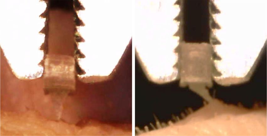
Wu et al. Microsystems & Nanoengineering (2021)7:58                                                           Page 3 of 13

PLA layers is critical. The anisotropic properties of the       The main difference in the morphology of the PLA
extruded PLA layers cause weak bonding between the            needles printed at different thermal parameters was the
layers. Weak bonding can lead to the detachment of PLA        strings between the PLA needles, as shown in Fig. 2. The
needles from the substrates during the etching process.       stringing phenomenon is a conventional challenge in the
Localized heating on the predeposition layer by a diode       FDM process26. The strings result from plastic residues on
laser can be used to enhance the interfacial bonding          the tip of the printing nozzle. In particular, strings are
strength. However, negative effects, such as hole forma-      formed when the nozzle travels from one point to another.
tion and breakage induced by the laser, can produce           This is because the higher thermal parameters trigger a
defects24. Yin et al. applied the intermolecular diffusion    longer duration of the molten state of the deposited PLA.
theory to predict the polymer interfacial bonding strength    The stringing phenomenon was more significant with a
during FDM processing25. The temperature of the print-        higher flowability of the deposited PLA. The PLA strings
ing stage significantly improves the bonding strength at       were removed by a subsequent etching process, as shown
the interfaces. Nevertheless, the influence of parameters      in Fig. 2. Chemical etching was performed in a 1 M sodium
during the chemical etching process is relatively             hydroxide (NaOH) solution at 55 °C. The stirring speed of
unknown.                                                      the etchant was set to 0 rpm throughout the entire pro-
  In this study, to facilitate welding on the interface of    cess. The interfacial bonding of the printed PLA needles
successive PLA layers, we investigated the optimal ther-      was significant during the etching process. Fractures on
mal parameters of the FDM process, such as the nozzle         the PLA needles printed at low thermal parameters
(T0) and printing stage (T∞) temperatures. The conditions     occurred after etching for 10 h (Fig. 2a3, b3). In contrast,
for the chemical etching process, such as the etchant         the substrates of the PLA needle array tended to collapse
concentration, environmental temperature, and stirring        upon further etching owing to the high void density
ratio of the etchant, were investigated to improve the        between the PLA layers. Consequently, the PLA needles
chemical etching efficiency. As illustrated in Fig. 1, to      detached from the substrate during subsequent etching.
weld the interfaces of successive PLA layers, PLA needles     Therefore, MN structures cannot be obtained from PLA
were initially printed using the FDM printer under opti-      needles printed with low thermal parameters. However,
mized conditions. The PLA needles were subsequently           PLA needles with high thermal parameters did not exhibit
chemically etched to reduce the dimensions of the PLA         fractures during the etching process. Owing to the incli-
needles to reach the micron scale. The fabricated PLA         nation angle, the diameter of the inclined needle was less
MNs could be coated with APIs for medical applications.       than that of the straight needle. Straight MN structures
This study optimizes the FDM-based fabrication process        were formed after etching for 30 h (Fig. 2c3). Inclined MN
for the batch fabrication of PLA MNs with pre-                structures were formed after 18 h of etching (Fig. 2d3).
programmable structures.                                      Both straight and inclined MNs had a needle length of
                                                              approximately 1000 µm. The straight and inclined MNs
Results                                                       had average tip diameters of 97 ± 21 and 86 ± 23 µm,
MNs fabrication via FDM and chemical etching                  respectively. The inclination angles of the MNs after
   The PLA needle array with predesigned structures was       chemical etching agreed well with the predesigned angles.
printed using an FDM printer (Fig. S1). Two types of PLA      Therefore, only PLA needles printed at high thermal
needles were used in this study, with needle lengths and      parameters can be used for subsequent chemical etching
layer diameters of 1 and 0.7 mm, respectively. The main       in the fabrication of MN structures.
difference between the two types of needles was the
inclination angle. The first needle type was a straight        Evaluation of PLA MNs
needle. The second was an inclined needle with an incli-        Strength tests were performed on both straight and
nation angle of 45°. All samples were printed with an infill   inclined MNs to evaluate the PLA MNs realized in this
density of 100% nominally to ensure that they were            study. The average failure force of straight MNs was
optimally solid. Parameters, such as the layer thickness,     10.5 ± 1.3 N. In contrast, the average failure force of the
line width, and printing speed, depend on the function of     inclined MNs was 4.8 ± 2.2 N. Representative force–
the FDM printer. Therefore, these parameters were set to      displacement curves of straight and inclined MNs are
the preferred setting of the FDM printer to guarantee the     shown in Fig. 3a. The set-up of the strength tests is shown
quality of the printed PLA objects. Different thermal         in Fig. S2. The results indicate that both straight and
parameters, such as T0 and T∞, were adjusted to investi-      inclined PLA MNs have sufficient strength (>58 mN) for
gate their influence. PLA needles were printed at low          insertion into skin27. Furthermore, both straight and
thermal parameter values (T∞ = 60 °C and T0 = 190 °C),        inclined MNs (a single MN on each patch) were inserted
as well as high thermal parameter values (T∞ = 120 °C and     into porcine skin, as shown in Fig. 3b1. The results
T0 = 210 °C).                                                 obtained from skin staining with methylene blue
Wu et al. Microsystems & Nanoengineering (2021)7:58                                                                                Page 4 of 13

                a1                                    a2                                    a3
                  Before etching                         After etching                           Fracture

                b1                                    b2                                    b3
                  Before etching                         After etching                           Fracture

                c1                                    c2                                    c3
                  Before etching                         After etching                         MN structure

                d1                                    d2                                    d3
                  Before etching                         After etching                         MN structure

 Fig. 2 Chemical etching on PLA needles printed at different thermal parameters. a1–a3 Chemical etching on straight PLA needles printed at
 low thermal parameters (T∞ = 60 °C and T0 = 190 °C). b1–b3 Chemical etching on inclined PLA needles printed at low thermal parameters (T∞ =
 60 °C and T0 = 190 °C). c1–c3 Chemical etching on straight PLA needles printed at high thermal parameters (T∞ = 120 °C and T0 = 210 °C). d1–d3
 Chemical etching on inclined PLA needles printed at high thermal parameters (T∞ = 120 °C and T0 = 210 °C)

(Fig. 3b2) confirmed that both straight and inclined MNs                   Carboxymethyl cellulose (CMC) loaded with 0.02 mg
pierced the stratum corneum of the skin samples. After                    rhodamine B was coated on the surface of each PLA MN
the MNs were inserted into the skin, force–displacement                   (Fig. 3e1, e2) to prepare the coated MNs (Fig. 3f1, f2). The
equipment was used to pull the MNs from the skin. The                     porous morphology of PLA MNs after chemical etching
average pulling-out forces of individual inclined and                     could possibly facilitate drug coating.
straight MNs were 29.7 ± 3.1 and 15.7 ± 3.2 mN, respec-                     In vitro transdermal drug delivery was conducted by
tively. The representative pulling force–displacement                     inserting straight and inclined MNs coated with rhodamine B
curves of straight and inclined MNs are plotted in Fig. 3c.               into porcine skin for 30 min. After the MNs were removed,
Inclined MNs triggered more significant deformations of                    the skin samples were sliced. Subsequently, the skin sections
the skin sample than straight MNs (Fig. 3d1) when pulled                  were observed under a fluorescence microscope. The heights
from the skin (Fig. 3d2). This result indicates that the                  of both the straight and inclined MNs were approximately
adhesion of the inclined MNs was stronger than that of                    1 mm. Fluorescence images (Fig. 3g1, g2) show significant
the straight MNs, which agrees with a previous study3.                    breaches on the stratum corneum. Furthermore, the
Wu et al. Microsystems & Nanoengineering (2021)7:58                                                                                                                                        Page 5 of 13

             a                    14
                                                                                             b1                                                           b2
                                           Straight MN
                                  12
                                           Inclined MN
                                  10
                                                                                                                                          Inclined MN
             Force (N)

                                   8

                                   6
                                                                                                                            Straight MN
                                   4

                                   2                                                                                                              2 mm                            2 mm

                                   0
                                       0   50     100       150   200     250    300   350
                                                        Displacement (μm)

             c                    30
                                                                                               d1                                                         d2
                                           Straight MN
                                  25
                                           Inclined MN
             Pulling force (mN)

                                  20

                                  15

                                  10

                                   5
                                                                                                                                                  1 mm                            1 mm

                                   0
                                       0    100     200     300      400        500    600
                                                     Displacement (μm)

                              e1                                   e2                                                            f1                          f2

                                                          500 μm                          500 μm                                                    500 μm                        500 μm

                                   g1

                                                                                             h 100
                                                                                                                                                                    Straight MN
                                                                                                                            90
                                                                                                                                                                    Inclined MN
                                                                                                                            80
                                                                                             Drug delivery efficiency (%)

                                                                                                                            70
                                                                                 500 μm
                                                                                                                            60

                                   g2                                                                                       50

                                                                                                                            40

                                                                                                                            30

                                                                                                                            20

                                                                                                                            10

                                                                                                                             0
                                                                                 500 μm                                                       1                        2
                                                                                                                                                         Time (h)

 Fig. 3 Evaluation results of the fabricated PLA MNs. a Strength tests of straight and inclined MNs. b1 Porcine skin inserted by straight and
 inclined MNs. b2 Skin sample stained by methylene blue. c Pulling force of straight and inclined MNs from the skin samples. The resolution of the
 force sensor is 1 mN. d1 Skin adhesion tests of straight MNs. d2 Skin adhesion tests of inclined MNs. e1 Straight MN before coating. e2 Inclined MN
 before coating. f1 Straight MN after coating. f2 Inclined MN after coating. g1 Fluorescence image of skin inserted by coated straight MNs. g2
 Fluorescence image of skin inserted by coated inclined MNs. h Drug delivery efficiency of the model drug from MNs to the skin, n = 3
Wu et al. Microsystems & Nanoengineering (2021)7:58                                                                                         Page 6 of 13

                    a           O                  b                   O                    c
                                                                                                       CH                           O
                    HO                                 HO
                                C                                      C                               CH            O              C
                          C             OH                     C           OH                                  C          CH
                                                                                                   O                                    n
                    H                               H3C
                              CH3                                  H                                           O          CH3

                        L-lactic acid                     D-lactic acid                                     Polylactic acid (PLA)

                    d   Glassy State           Ductile State                     Molten state                        Decomposition

                                       Tg                       Tm
                                                                                                       215–285 °C
                                    55–80 °C                130–175 °C

                                             Temperature for                    Temperature for
                                              printing stage                     printing nozzle

 Fig. 4 Physicochemical properties of PLA. a Chemical structure of L-lactic acid. b Chemical structure of D-lactic acid. c Configuration of PLA.
 d Metastable states of PLA

fluorescence components reached a depth of approximately                            Fig. 4d. The glass transition temperature (Tg) indicates the
500 µm from the surface of the skin. Therefore, both the                           transition between the glassy and ductile states. Tem-
straight and inclined MNs penetrated the stratum corneum                           peratures above Tg can induce drastic changes in the
and epidermis. In addition, owing to its elastic properties,                       polymer chain mobility. For PLA, Tg can be represented
skin can be deformed when pressure is applied. Therefore,                          by the Flory–Fox equation31:
the entire shaft of the MN cannot be completely inserted into
the skin.                                                                               Tg  Tg1  K =Mn                                            ð1Þ
  To determine the drug delivery efficiency of the coated
PLA MNs, both coated straight and inclined MNs were                                where Tg1 represents the Tg of the number-average
inserted into porcine skin for certain durations. The mass                         molecular weight (Mn) and K is an empirical constant
of rhodamine B (model drug) remaining on the MNs was                               that indicates the excess free volume for the end groups of
determined using a microplate reader. As shown in Fig.                             the polymer chains. Jamshidi et al. demonstrated that the
3h, after insertion into skin for 1 h, both the straight and                       Tg of D,L-lactic acid (PDLLA) is higher than that of poly L-
inclined MNs delivered 35% of the model drug into the                              lactic acid. The reason for this difference is partly due to
skin. Furthermore, the drug delivery efficiency of MNs                              the crystallinity of the two polymers31. Therefore, the Tg of
reached 75% after insertion for 2 h.                                               PLA adopted for FDM is not a universal constant. Du et al.
                                                                                   reported that the Tg of PLA ranges from 55 to 80 °C32.
Discussion                                                                           The melting temperature (Tm) of PLA depends on the
Physical characteristics of PLA                                                    presence of PDLLA in the structure and is given by16:
  The repeat unit of the general PLA contains a stereo-
center that is either L- or D-lactic acid, as illustrated in Fig.                       Tm  175  300Wm                                            ð2Þ
4a–c. Commercially available PLA for practical FDM
processing comprises a mixture of L- and D-lactic acids                            where Wm represents the fraction of PDLLA in the
but with a major proportion of L-lactic acid. The stereo-                          structure. The melting point of PLA composed of 100% L-
chemistry of PLA is complicated owing to its chiral nat-                           lactic acid is 175 °C. The Tm of a typical PLA ranges from
ure. PLA can be semicrystalline with components of >93%                            130 to 175 °C16.
L-lactic acid, whereas components of L-lactic acid ranging                           When PLA is heated above Tm, it rapidly loses its
from 50 to 93% can make PLA strictly amorphous28. The                              thermal stability. Moreover, significant molecular weight
reported molecular weight of PLA for FDM is                                        degradation occurs when heating lasts for a long period at
50–140 kDa, which is required to stabilize the viscosity of                        a temperature of 10 °C above the melting point. Migliaresi
molten PLA during the extrusion process29,30.                                      et al. reported that the thermal degradation of PLA is due
  The relationship between the metastable states of high                           to chain splitting33. Amorphous PLA decomposes
molecular weight PLA and temperature is shown in                                   between 215 and 285 °C16. During FDM processing, the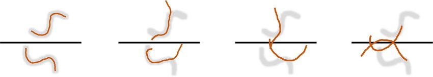
Wu et al. Microsystems & Nanoengineering (2021)7:58                                                              Page 7 of 13

Table 1 Thermal properties of the PLA filament and PLA           diameters of the deposited PLA disks. Zhang et al.
processing parameters.                                          reported that an optimized combination of parameters,
                                                                such as the line width, layer thickness, and printing speed,
                                                      Value
                                                                can reduce the dimensional error during the FDM
Thermal properties of PLA                                       printing process34. However, the optimized parameter
                                                                combination varies between FDM printers. In contrast,
  Thermal conductivity, k (W/m·K)                     0.13
                                                                the positions of the printing nozzle and printing stage can
  Specific heat, C (J/kg·K)                            1800      be controlled to the required layer thickness by fixing the
  Density, ρ (kg/m3)                                  1240      gap distance between the nozzle and stage. Similar to the
  Glass transition temperature, Tg (°C)               60        initial layer, the thickness of each layer was controlled.
                                                                Accordingly, the length of the printed PLA needles can
  Melting temperature, Tm (°C)                        170
                                                                also be controlled.
  Decomposition temperature, Td (°C)                  220         During the layer-by-layer deposition process, the layers
Parameters during FDM printing                                  were composed of partially bonded PLA lines and voids
  Infill density (%)                                   100       between two successive layers, as illustrated in Fig. 5b.
                                                                Until the PLA was cooled below the glass transition
  Printing speed, v (mm/s)                            60
                                                                temperature, the mobility of the polymer chains inside the
  Layer thickness, Lt (µm)                            100       extruded PLA was activated35. The mobility of the poly-
  Line width, Lw (µm)                                 700       mer chains continuously facilitates coalescence between
  Nozzle temperature, T0 (°C)                         190–210   neighboring PLA lines. Furthermore, the PLA in the
                                                                molten state exhibited better flowability than that in the
  Printing stage temperature, T∞ (°C)                 60–120
                                                                ductile state. The conventional reptation model was used
                                                                to describe the motion of random coil chains at the
                                                                interfaces of the molten polymer within the relaxation
stage temperature of the FDM printer should be set              time, as illustrated in Fig. 5c. The PLA molecular chain
between Tg and Tm to ensure that the bottom layer is            near the interface is initially confined in a tube, which is a
firmly adhered to the stage. The printing nozzle should be       topological constraint that restricts the motion of the
set above Tm but below the decomposition temperature            chain. Brownian motion enables the chain ends to escape
for the smooth extrusion of PLA. For the PLA filament            from the initial tubes as random coil chains obeying
employed in this study, Tg and Tm were 60 and 170 °C,           Gaussian statistics36. The PLA random coil chains diffuse
respectively. Furthermore, the decomposition tempera-           across the interface of neighboring PLA lines and entangle
ture of the PLA filament is 220 °C (Table 1).                    PLA chains from the other side of the interface to weld
                                                                the interface. The number (n) of random coil chains dif-
AM of PLA needles                                               fusing across the unit area of the interface can be
  The molten PLA extruded from the nozzle can fabricate         expressed by Eqs. 3 and 4:
objects layer by layer in the FDM. Before the hardening
and solidification of the previous layer, the polymer chains
of PLA diffuse across the interfaces between successive             nðtÞ  t 1=4 M 5=4 ; ðt < tr Þ                      ð3Þ
layers to form bonds. When the FDM is adopted to print
objects with micron-scale structures, the printable                 n1  M 1=2 ; ðt  tr Þ                              ð4Þ
dimensions depend on the printing unit of the FDM
printer. The PLA needles were accumulated by the                where t and M represent the contact time of successive
printing units extruded from the nozzle, as illustrated in      molten PLA lines and molecular weight of the polymer
Fig. 5a. The profile of the printing unit has an oblong          chains, respectively. In addition, tr represents the relaxa-
shape, which is influenced by two parameters: line width         tion time of the polymer chain, and in the dynamic
and layer thickness. Herein, the minimum diameter of the        polymer solution, tr ≈ M3 36.
printing unit, which is termed “line width”, is limited by        This indicates that the interfaces of successive PLA
the size of the nozzle. In this study, a nozzle with a dia-     layers can be welded to a virgin state by contacting the
meter of 500 µm was used for printing. In addition, the         molten PLA depositions until the relaxation time. How-
PLA disks deposited after solidification are expected to         ever, during the FDM deposition process, the two layers
have diameters >500 µm, considering the thermal defor-          remain in the molten state for a limited time owing to
mation of the heating nozzle.                                   natural cooling. A conventionally accepted analytical
  Dimensional error is a conventional challenge during          solution by Bellehumeur et al. uses a lumped capacity
the FDM process, which triggers nonuniformity in the            analysis to predict the cooling time of the extruded layer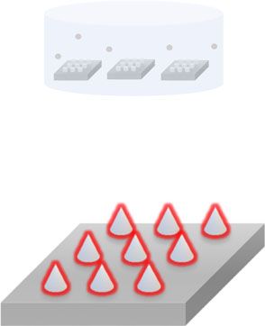
Wu et al. Microsystems & Nanoengineering (2021)7:58                                                                                                   Page 8 of 13

                    a
                                     Printing nozzle

                                                                                                                   Molten PLA
                        PLA needle with
                        minimum diameter
                                                                                                                                  Nozzle size

                                                                                                                                  Layer thickness

                                                                               Printing unit

                                                                       PLA substrate for
                                                                         needle array                              Line width

                    b

                                      Unit between successive layers

                                                                                 Contact of neighboring lines           Coalescence of neighboring
                                                                                  with weak coalescence of                 lines with diffusion of
                                                                                 polymer chains at interface            polymer chains at interface

                    W= Layer thickness of PLA          L=Line width of PLA

                    c                        Chain end                Escape                            Disengage                      Weld
                              Initial tube

                     Interface

                                         t=0                          t = t1                              t = t2                       t = tr
                                                                                     t < t1 < t2 < tr

 Fig. 5 Illustration of PLA objects printed by the FDM printer. a The dimension of the printing unit is limited by the nozzle size. b The cross-
 sectional structure of the FDM-printed PLA objects comprises bonded PLA lines and voids between successive layers. c Reptation model depicting
 the behavior of PLA molecular chains during the interfacial diffusion process, where tr represents the tube relaxation or disengagement time

during the FDM process37,38:                                                          PLA, respectively. In addition, h is the free convection
                                                                                    from the extruded PLA to the envelope air, which is
          ln   T T1                                                                 estimated to be 50–100 W/m2·K, while ρ, k, and C
    t¼
                T0 T1                                                       ð5Þ      represent the density, thermal conductivity, and specific
                mv                                                                    heat of the PLA, respectively.
where T and T∞ represent the transient temperature of                                   The reptation model assumes that the contacting
the extruded PLA layer during cooling and envelope                                    polymers are in a molten state. Equation 5 can be adopted
temperature around the extruded PLA layer, respectively.                              to predict the cooling time between the extrusion and
T∞ was assumed to be consistent with the printing stage                               melting temperature. For the T = Tm case, increasing both
temperature because the printed PLA needle patch in this                              T∞ and T0 can extend the diffusion time of PLA chains at
study was relatively thin.T0 represents the extrusion                                 the interfaces before cooling below Tm. The extended
temperature of the PLA, which is the same as the nozzle                               diffusion time at the interfaces of the PLA layers can
temperature, and v is the constant moving speed of the                                facilitate bonding between successive layers, as expressed
nozzle during the printing of one layer. Furthermore, m ¼                             by Eq. 3. Notably, the profile of the extruded PLA lines
pffiffiffiffiffiffiffiffiffiffi
  1þ4αβ1          k             hP                                                   and printing speed depend on the functions of the FDM
    2α      , α ¼ ρCv , and β ¼ ρCAv , where A and P represent
                                                                                      printer. These two parameters significantly influence the
the cross-sectional area and perimeter of the extruded                                quality of the printed objects. A, P, and v were set as the
Wu et al. Microsystems & Nanoengineering (2021)7:58 Page 9 of 13
preferred settings for the FDM printer. Therefore, they Coalescence of PLA layers
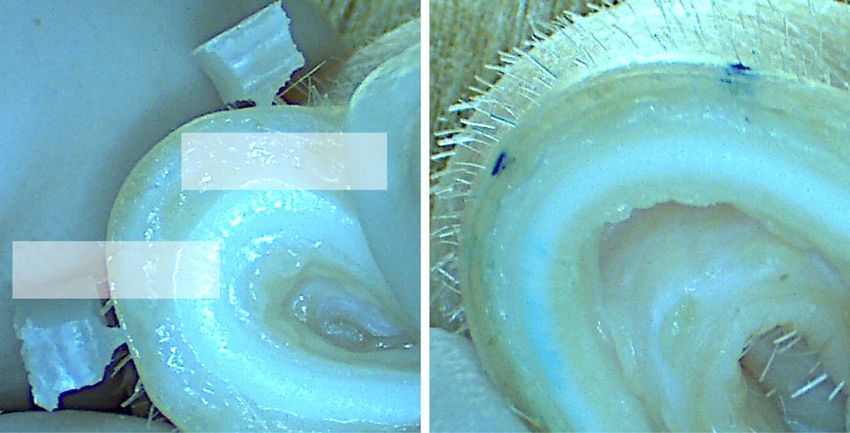
are constant in Eq. 5. The fractured surfaces of representative samples printed
Inadequate contact between neighboring PLA lines with different combinations of T0 and T∞ are presented in
triggers the formation of voids between layers. A rectan- Fig. 6a. Although the nominal infill density was set to
gular unit between two successive layers is determined by 100%, the cross-sections of the PLA substrates still
the line width and layer thickness of PLA. The void exhibited voids between successive layers. The results in
density in the area of the rectangular unit was measured Fig. 6b indicate that the void density can be reduced as
via microscopy and analyzed using the ImageJ software. both T0 and T∞ increase. If T∞ is increased, then the void
Equation 5 indicates that the cooling time until the density can be effectively reduced with a constant T0
solidification of PLA is linear with a value of ln TTm0 T
T1
. value. Because the printing stage was heated above the
1
glass transition temperature of PLA, the PLA in the
If the other parameters are constant, then different ductile state filled the internal voids under the influence of
combinations of T0 and T∞ can trigger different bonding gravity. This was because the PLA needles accumulated
performances between the contacted PLA layers. With by the deposition of the printing units. The challenge of
respect to the FDM printer used in this study, the max- voids inside needle structures can be ignored. The
imum T∞ is 120 °C. Therefore, T∞ was set to the range bonding strength of the successive PLA layers of the PLA
60–120 °C during the printing process. In addition, the needles was investigated by pulling the PLA needles from
nozzle temperature was kept below 210 °C to avoid the substrate using force–displacement equipment.
decomposition of the PLA. Based on the thermal prop- Equations 3 and 5 indicate that the bonding performance
erties of the PLA filament in this study, the printing of successive PLA layers is positively correlated with the
nozzle temperature of the FDM was set to 190–210 °C
during the printing process. value of ln TTm0 T
T1
1
, which is herein defined as Q. The
a b 20
T ∞ = 60 °C; T 0 = 190 °C T ∞ = 60 °C; T 0 = 210 °C
18
12.41±3.99
16
14
Void density (%)
12
Unit between layers Unit between layers
10
6.42±1.83
T ∞ = 120 °C; T 0 = 190 °C T ∞ = 120 °C; T 0 = 210 °C 8
6 3.37±1.44
4
2 0.96±0.57
Unit between layers Unit between layers 0
T ∞ = 60 °C T ∞ = 60 °C T ∞ = 120 °C T ∞ = 120 °C
T 0 = 190 °C T 0 = 210 °C T 0 = 190 °C T 0 = 210 °C
c 60
d 60
T ∞ = 60 °C; T 0 = 190 °C Bonding strength of virgin-state PLA: 51 MPa
50 T ∞ = 60 °C; T 0 = 210 °C 50
43.93±2.47
Bonding strength (MPa)
T ∞ = 120 °C; T 0 = 190 °C
40 40 32.04±4.26
T ∞ = 120 °C; T 0 = 210 °C
Stress (MPa)
30.13±3.81
30 30 19.70±8.06
20 20
10 10
0 0
0.0 0.1 0.2 0.3 0.4 0.5 0.6 T ∞ = 60 °C T ∞ = 60 °C T ∞ = 120 °C T ∞ = 120 °C
Displacement (mm) T 0 = 190 °C T 0 = 210 °C T 0 = 190 °C T 0 = 210 °C
Q = 0.16 Q = 0.32 Q = 0.34 Q = 0.58
Fig. 6 Coalescence of PLA layers at different nozzle and printing stage temperatures. a SEM images of cross-sectional views of PLA substrate
printed under different conditions. b Average void density of PLA substrates printed under different conditions, n = 4. c Representative
stress–displacement curves of uniaxial tensile tests for PLA needles printed under different conditions. d Average bonding strength of PLA needles
T1
printed under different conditions, Q ¼ ln TTm0 T1
and n = 6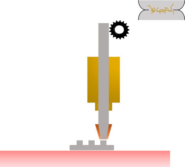
Wu et al. Microsystems & Nanoengineering (2021)7:58                                                            Page 10 of 13

numerical results of the bonding strengths measured by           the etchant. Furthermore, once the concentration of
tensile tests, as presented in Fig. 6c, d, agree well with the   hydroxide ions reached 1 M (pH = 14), increasing the
corresponding Q. Furthermore, the measured tensile               concentration of the etchant was ineffective in accelerat-
strength of the PLA filament in the virgin state was              ing the etching ratio. This result can be attributed to the
approximately 51 MPa using the force–displacement                saturation of hydroxide ions inside the solvent. In addi-
machine. The experimental data indicated that the                tion, it was evident that the high temperature of the
interfaces of successive PLA layers could be welded. The         etchant significantly accelerated the etching ratio, as
bonding strength of the PLA needles increased from               shown in Fig. 7c. This result can be explained by the
19.70 MPa (Q = 0.16) to 43.93 MPa (Q = 0.58) as T0 and           theory of thermodynamics, which indicates that a higher
T∞ increased from their minimum to maximum values. In            temperature promotes the diffusion of molecules. Water
this study, the welding of the layer interface could not         molecules, together with hydroxide ions, need to pene-
reach the virgin state of PLA with the maximum T0 and            trate and diffuse into the PLA polymer matrix to break the
T∞. An optimized bonding strength of PLA needles is              ester bones. Increasing the temperature accelerated the
necessary to avoid detachment during the chemical                hydrolysis of PLA. However, the stirring speeds of the
etching process.                                                 etchants did not significantly influence the etching ratio,
  Yin et al. reported that optimizing the nozzle tem-            as shown in Fig. 7d. This result agrees well with that of a
perature or printing stage temperature can improve the           previous study by Román-Ramírez et al. It has been
interfacial bonding strength of FDM-printed objects25. In        reported that the catalyst-mediated hydrolysis of PLA
this study, a polymer reptation model and prediction             does not exhibit mass-transfer limitations owing to
model for the cooling time of a polymer extruded by FDM          stirring23.
were employed. The combination of these two models
offers universal optimization for the entire FDM process.        Conclusion
Interfacial bonding was mutually influenced by T0 and T∞.           We investigated an optimized methodology for the
The void density and interfacial bonding between suc-            fabrication of PLA MNs with tailored structures. A
cessive PLA layers are critical in subsequent chemical           parametric study of the influence of PLA layers on the
processes. PLA needles with weak interfacial bonding and         interfacial bonding strength was conducted by investi-
high void density will trigger detachment of the PLA             gating the nozzle and printing stage temperatures of the
needles and collapse of the substrate during etching,            FDM process. Within the temperature range that the
resulting in production failures and waste of raw                FDM printer and PLA filament can withstand, increasing
materials.                                                       the thermal parameters during the FDM process was
                                                                 demonstrated to improve the interfacial bonding strength
Chemical etching process                                         and decrease the void density of the PLA layers. The
  The concept of combining FDM processing and che-               optimized PLA needle array can effectively prevent
mical etching to fabricate PLA MNs has previously been           detachment of the PLA needles and collapse of the sub-
proposed18,19. However, the bonding limitations of PLA           strates during etching. This study suggests that increasing
layers during FDM processing have yet to be addressed.           the concentration and temperature of the etchant can
The PLA needles printed via FDM have uneven profiles              improve the efficiency of chemical etching. Based on these
owing to the layer-by-layer deposition process. The              findings, a customized methodology was developed for
simulation of the transformation of PLA needle structures        the fabrication of biodegradable MNs. Our study is
during the etching process demonstrated that barbed              expected to provide the MN field with a method for
profiles could be smoothed with isotropic etching on the          fabricating MN structures for various biomedical appli-
bulks of the needle patches (Fig. 7a). Furthermore, the          cations without expertise in microfabrication.
chemical etching of PLA needles printed with different
layer thicknesses was simulated (Fig. S3) and experi-            Materials and methods
mentally investigated (Fig. S4). The results indicated that      FDM printing of PLA needles
the barbed PLA MNs reported by Luzuriaga et al. were               The PLA needles in this study were printed using an
potentially due to inadequate etching19.                         FDM printer (Taz 6, Lulzbot, USA) in a layer-by-layer
  A PLA needle array printed with Q = 0.58 (T∞ = 120 °C          manner prior to chemical etching. The geometrical
and T0 = 210 °C) was chemically etched (Fig. S5a). The           structures of the printing objects were designed using the
curves of the etched amount within 20 h were fitted lin-          Fusion 360 software and converted into G-code using the
early (Fig. S5b–d) to obtain PLA etching ratios. The             Cura software, which can be recognized by the FDM
etching ratios of PLA under different conditions were            printer for printing. The thermal properties of the com-
measured and are presented in Fig. 7b–d. As shown in Fig.        mercial PLA filament (16609, Mutoh, Japan) and printing
7b, the etching ratio increased with the concentration of        parameters employed in this study are listed in Table 1.
Wu et al. Microsystems & Nanoengineering (2021)7:58 Page 11 of 13
a b 5
3.82±0.18
200 μm
4
3.31±0.1
Etching ratio (μm/h)
3
2
1.35±0.17
1
0.08±0.02
0
0 0.5 1 4
Concentration of the etchant (M)
c 15 d 5
11.75±0.15
4
3.31±0.1 3.43±0.03
Etching ratio (μm/h)
Etching ratio (μm/h)
3±0.19
10 8.25±0.39
3
2
5
3.31±0.1
1
0 0
25 40 55 0 100 200
Temperature of the etchant (°C) Stirring speed of the etchant (rpm)
Fig. 7 Characteristics of the chemical etching process. a Simulation of the transformations of PLA needles during the chemical etching process.
The etched amount of each step in the simulation is approximately 70 µm. b Etching ratios of PLA needles in NaOH solution at different
concentrations. The temperature is 25 °C, and the etchant stirring speed is 0 rpm for each condition. c Etching ratios of PLA needles in 1 M NaOH
solution at different temperatures. The stirring speeds of the etchants are all set to 0 rpm. d Etching ratios of PLA needles in 1 M NaOH solution at
different stirring speeds. The temperatures of the etchants are all set to 25 °C
Chemical etching by hydrolysis temperature of the etchant was controlled by a heater
The degradation of PLA can be considered a post- (temperature in the range 25–55 °C). Furthermore, the
fabrication method to reduce the size of FDM-printed stirring speed of the stirring bar inside the beaker was
PLA needles. There are four main irreversible degradation varied from 0 to 200 rpm. The dimensions of the PLA
mechanisms of PLA: photodegradation, microbial degra- needles before and after chemical etching were measured
dation, enzymatic degradation, and hydrolysis39. In the using an optical digital microscope (VHX-2000, Keyence,
case of hydrolysis, water molecules break the ester bonds Japan). The changes in the diameters in the middle parts
of PLA, which constitute the polymer bones. Degradation of the PLA needles were measured every 5 h after che-
can homogeneously act on the PLA surface, which is an mical etching. The etched quantities of PLA needles
essential criterion for postprocessing FDM-printed PLA within 20 h were plotted using the Origin software. The
needles. Therefore, the hydrolysis of PLA was used for curves were linearly fitted to yield the etching ratios under
chemical etching in this study. different etching conditions.
The dimensions of the PLA needles during the etching
process were simulated by the MATLAB software using Mechanical tests
the function “distance transform”. To investigate the The interfacial bonding strength between successive
influence of different conditions during chemical etching, PLA layers is defined as the tensile strength at the inter-
etchants with concentrations of sodium hydroxide face of the PLA layers. PLA needles printed with different
(221465, Sigma, USA) ranging from 0 to 4 M were pre- thermal properties were evaluated by uniaxial tensile tests
pared. A beaker containing 300 mL of NaOH solution was using commercial force–displacement equipment (MX2-
placed on a magnetic stirrer (HS 7, IKA, Japan). The 500N, Imada, Japan). The grip of the equipment pulled upWu et al. Microsystems & Nanoengineering (2021)7:58 Page 12 of 13
the PLA needles at a speed of 2 mm/min. The bonding solution was coated on the surface of the PLA MNs42.
strength (σ) of the PLA needles was calculated by: Rhodamine B was used as the model drug in this study.
After the MNs were achieved, 1 µL of solution was dis-
F pensed on each MN using a micropipette. The coated
σ¼ ð6Þ
S MNs were heated in an oven at 50 °C for 5 min to solidify
where F is the stretching force and S is the cross-sectional the coating ingredients.
area of the PLA needles.
The strengths of the PLA MNs after chemical etching In vitro transdermal drug delivery
were measured by compressing the MNs at a speed of Before the test, the skin samples were thawed at 25 °C
2 mm/min using the force–displacement equipment. for 20 min and then completely shaved. Then both coated
straight and inclined MN patches were inserted into the
Evaluation of skin insertion and adhesion porcine ear skin for certain durations. After the MNs were
PLA MN array patches were applied to the stratum peeled off, the skin samples were sliced. The skin sections
corneum of porcine ear skin (K1270, Funacoshi, Japan). were observed using a stereomicroscope (IX71, Olympus,
The criteria for selecting skin samples were based on their Japan) to obtain fluorescence images.
similarities with human skin in terms of physiology and
anatomy40. The puncturing by the PLA MNs was con- Drug loading and drug delivery efficiency
firmed via a skin staining technique using a 10 mg/mL The drug loading and drug delivery efficiency of rho-
methylene blue (M9140, Sigma-Aldrich, USA) solution. damine B (model drug) were measured using a microplate
Methylene blue is a dye used for biological staining, in reader (H1, BioTek, USA). Rhodamine B in deionized (DI)
which dye molecules bind with proteins in tissues (other water at different concentrations (0.5–8 mg/L) created a
than the stratum corneum). The methylene blue solution, spectral profile at wavelengths of 400–600 nm using a
which has a low molecular weight and is hydrophilic, microplate reader (Fig. S6a). The maximum absorption of
cannot be absorbed by the hydrophobic stratum cor- light by the chromophore group occurred at a wavelength
neum41. After removal of the PLA MN arrays from the of 555 nm. When the concentration of rhodamine B
porcine skin, the methylene blue solution was deposited ranged from 0.5 to 8 mg/L, the absorbance of light at
on the skin surface for 10 min. The solution was subse- 555 nm by rhodamine B was linear with the concentration
quently wiped away using ethanol (24194, Sigma-Aldrich, (Fig. S6b). After dissolving one coated PLA MN in 5 mL
USA), leaving the dye only in regions where the stratum DI water, the drug loading of rhodamine B on each MN
corneum had been punctured. was calculated using the calibration curve. After in vitro
The adhesion performance of the individual PLA MNs transdermal drug delivery tests, each MN was dissolved in
was evaluated after skin insertion using the 5 mL of DI water. Using the same method, the amount of
force–displacement equipment. In this study, skin sam- rhodamine B remaining on each MN after the tests was
ples inserted with PLA MN arrays were fixed on the stage calculated. Finally, the drug delivery efficiency was
of the force–displacement equipment. A grip was used to calculated.
pull the MN arrays out of the skin. The maximum force
required to pull out the MN from the skin sample was Acknowledgements
This research was funded by the Global Leader Program for Social Design and
used to assess adhesion performance. Management (GSDM) from the University of Tokyo and partially supported by
the JSPS Core-to-Core program A. The authors thank Professor Suzuki
Scanning electron microscopic (SEM) characterization Hiromasa at the University of Tokyo for his advice on the MATLAB simulation,
Professor Minami and Mr. Lv Xiaojun at the University of Tokyo for their
A scanning electron microscope (JSM-6060, JEOL, assistance with the operation of the microplate reader, and Dr. Wu Yunhui and
Japan) was used to observe the PLA objects presented in Mr. Cai Yicheng for their advice during the experimental process at the
this study. Prior to observation, a 12-nm-thick layer of University of Tokyo.
gold was coated on the surface using a thin-film coater
Author contributions
(SC-701Mk, Sanyu Electron, Japan). Cross-sectional views B.K. initiated the project. L.W. developed the methodology and fabricated and
of the PLA layers were observed using SEM. The void characterized the devices. L.W. and Y.K. performed the experiments and data
densities were subsequently calculated using the ImageJ curation. L.W. wrote the original manuscript. J.P. and B.K. reviewed and
commented on the manuscript. All authors read and approved the final
software. manuscript.
Drug coating Conflict of interest
An aqueous solution of 20 mg/mL rhodamine B (83689, The authors declare no competing interests.
Sigma-Aldrich, USA) and 80 mg/mL CMC (C5678,
Sigma-Aldrich, USA) was prepared as the coating ingre- Supplementary information The online version contains supplementary
dient. CMC served as the thickener to ensure that the material available at https://doi.org/10.1038/s41378-021-00284-9.Wu et al. Microsystems & Nanoengineering (2021)7:58 Page 13 of 13
Received: 12 February 2021 Revised: 7 June 2021 Accepted: 11 June 2021 22. Alexis, F. Factors affecting the degradation and drug‐release mechanism of
poly (lactic acid) and poly [(lactic acid)‐co‐(glycolic acid)]. Polym. Int. 54, 36–46
(2005).
23. Román-Ramírez, L. A., Mckeown, P., Jones, M. D. & Wood, J. Poly (lactic acid)
degradation into methyl lactate catalyzed by a well-defined Zn (II) complex.
References ACS Catal. 9, 409–416 (2018).
1. Prausnitz, M. R., Mitragotri, S. & Langer, R. Current status and future potential of 24. Sabyrov, N., Abilgaziyev, A. & Ali, M. H. Enhancing interlayer bonding strength
transdermal drug delivery. Nat. Rev. Drug Discov. 3, 115–124 (2004). of FDM 3D printing technology by diode laser-assisted system. Int. J. Adv.
2. Kim, Y. C., Park, J. H. & Prausnitz, M. R. Microneedles for drug and vaccine Manuf. Technol. 108, 603–611 (2020).
delivery. Adv. Drug Deliv. Rev. 64, 1547–1568 (2012). 25. Yin, J., Lu, C., Fu, J., Huang, Y. & Zheng, Y. Interfacial bonding during multi-
3. Zhang, X. et al. Claw-inspired microneedle patches with liquid metal encap- material fused deposition modeling (FDM) process due to inter-molecular
sulation for accelerating incisional wound healing. Chem. Eng. J. 406, 126741 diffusion. Mater. Des. 150, 104–112 (2018).
(2021). 26. Bryll, K., Piesowicz, E., Szymański, P., Ślączka, W. & Pijanowski, M. Polymer
4. Lee, H. et al. Porous microneedles on a paper for screening test of prediabetes. composite manufacturing by FDM 3D printing technology. In MATEC Web of
Med. Devices Sens. 3, e10109 (2020). Conferences 02006 (EDP Sciences, 2018).
5. Lee, H. S., Ryu, H. R., Roh, J. Y. & Park, J. H. Bleomycin-coated microneedles for 27. Park, J. H., Allen, M. G. & Prausnitz, M. R. Biodegradable polymer microneedles:
treatment of warts. Pharm. Res. 34, 101–112 (2017). fabrication, mechanics and transdermal drug delivery. J. Controlled Release 104,
6. Jiang, J. et al. Coated microneedles for drug delivery to the eye. Investig. 51–66 (2005).
Ophthalmol. Vis. Sci. 48, 4038–4043 (2007). 28. Kharas, G. B, Sanchez-Riera, F & Severson, D. K. in Plastics from Microbes (ed.
7. Liebl, H. & Kloth, L. C. Skin cell proliferation stimulated by microneedles. J. Am. Mobley, D. P.) 93–258 (Hanser Publishers, 1994).
Coll. Clin. Wound Spec. 4, 2–6 (2012). 29. Balani, S. B., Chabert, F., Nassiet, V. & Cantarel, A. Influence of printing para-
8. Takeuchi, K. & Kim, B. Functionalized microneedles for continuous glucose meters on the stability of deposited beads in fused filament fabrication of poly
monitoring. Nano converg. 5, 1–10 (2018). (lactic) acid. Addit. Manuf. 25, 112–121 (2019).
9. Park, J. H., Allen, M. G. & Prausnitz, M. R. Biodegradable polymer microneedles: 30. Schwartz, J. J., Hamel, J., Ekstrom, T., Ndagang, L. & Boydston, A. J. Not all PLA
fabrication, mechanics and transdermal drug delivery. J. Controlled Release filaments are created equal: an experimental investigation. Rapid Prototyp. J.
104, 51–66 (2005). 26, 1263–1276 (2020).
10. Lee, K. & Jung, H. Drawing lithography for microneedles: a review of funda- 31. Jamshidi, K., Hyon, S. H. & Ikada, Y. Thermal characterization of polylactides.
mentals and biomedical applications. Biomaterials 33, 7309–7326 (2012). Polymer 29, 2229–2234 (1988).
11. Han, D. et al. 4D printing of a bioinspired microneedle array with backward‐ 32. Du, F., Schick, C. & Androsch, R. Full-composition-range glass transition
facing barbs for enhanced tissue adhesion. Adv. Funct. Mater. 30, 1909197 behavior of the polymer/solvent system poly (lactic acid)/ethyl butylacetyla-
(2020). minopropionate (PLA/IR3535®). Polymer 209, 123058 (2020).
12. Lim, S. H. et al. High resolution photopolymer for 3D printing of personalised 33. Migliaresi, C., Cohn, D., De Lollis, A. & Fambri, L. Dynamic mechanical and
microneedle for transdermal delivery of anti-wrinkle small peptide. J. Con- calorimetric analysis of compression‐molded PLLA of different molecular
trolled Release 329, 907–918 (2020). weights: effect of thermal treatments. J. Appl. Polym. Sci. 43, 83–95 (1991).
13. Uddin, M. J. et al. 3D printed microneedles for anticancer therapy of skin 34. Zhang, J. W., & Peng, A. H. in Advanced Materials Research, Vol. 538 (ed.
tumours. Mater. Sci. Eng. C 107, 110248 (2020). Kawazoe, Y.) 444–447 (Trans Tech Publications Ltd, 2012).
14. Farah, S., Anderson, D. G. & Langer, R. Physical and mechanical properties of 35. Thomas, J. P., & Rodríguez, J. F. Modeling the fracture strength between fused-
PLA, and their functions in widespread applications—a comprehensive deposition extruded roads. In 2000 International Solid Freeform Fabrication
review. Adv. Drug Deliv. Rev. 107, 367–392 (2016). Symposium (2000).
15. da Silva, D. et al. Biocompatibility, biodegradation and excretion of polylactic 36. Wool, R. P., Yuan, B. L. & McGarel, O. J. Welding of polymer interfaces. Polym.
acid (PLA) in medical implants and theranostic systems. Chem. Eng. J. 340, Eng. Sci. 29, 1340–1367 (1989).
9–14 (2018). 37. Bellehumeur, C., Li, L., Sun, Q. & Gu, P. Modeling of bond formation between
16. Auras, R., Harte, B. & Selke, S. An overview of polylactides as packaging polymer filaments in the fused deposition modeling process. J. Manuf. Process.
materials. Macromol. Biosci. 4, 835–864 (2004). 6, 170–178 (2004).
17. Sharma, M. in Applications of Targeted Nano Drugs and Delivery Systems (eds 38. Zhou, X., Hsieh, S. J. & Sun, Y. Experimental and numerical investigation of the
Mohapatra, S. S., Ranjan, S., Dasgupta, N., Mishra, R. K. & Thomas, S.) Ch. 18 thermal behaviour of polylactic acid during the fused deposition process.
(Elsevier, 2019). Virtual Phys. Prototyp. 12, 221–233 (2017).
18. Wu, L., Coleman, A. & Kim, B. Investigation on 3D printing assisted metho- 39. Zaaba, N. F. & Jaafar, M. A review on degradation mechanisms of polylactic
dology for microneedle fabrication. In 5th International Conference on Micro- acid: hydrolytic, photodegradative, microbial, and enzymatic degradation.
needles, 64 (2018). Polym. Eng. Sci. 60, 2061–2075 (2020).
19. Luzuriaga, M. A., Berry, D. R., Reagan, J. C., Smaldone, R. A. & Gassensmith, J. J. 40. Summerfield, A., Meurens, F. & Ricklin, M. E. The immunology of the porcine
Biodegradable 3D printed polymer microneedles for transdermal drug skin and its value as a model for human skin. Mol. Immunol. 66, 14–21 (2015).
delivery. Lab Chip 18, 1223–1230 (2018). 41. Moronkeji, K., Todd, S., Dawidowska, I., Barrett, S. D. & Akhtar, R. The role of
20. Wu, L. et al. Characterization method for calculating diffusion coefficient of subcutaneous tissue stiffness on microneedle performance in a representative
drug from polylactic acid (PLA) microneedles into the skin. J. Drug Deliv. Sci. in vitro model of skin. J. Controlled Release 265, 102–112 (2017).
Technol. 61, 102192 (2021). 42. Chen, J., Qiu, Y., Zhang, S., Yang, G. & Gao, Y. Controllable coating of micro-
21. Casalini, T. in Bioresorbable Polymers for Biomedical Applications (eds Perale, G. & needles for transdermal drug delivery. Drug Dev. Ind. Pharm. 41, 415–422
Hilborn, J.) 65–83 (Woodhead Publishing, 2017). (2015).You can also read