Three-Dimensional In Situ Texture Development and Plasticity Accumulation in the Cyclic Loading of an α-Ti Alloy
←
→
Page content transcription
If your browser does not render page correctly, please read the page content below
Three-Dimensional In Situ Texture Development and Plasticity
                                                                   Accumulation in the Cyclic Loading of an α-Ti Alloy

                                                           Rachel E. Lima,∗, Joel V. Bernierb , Darren C. Paganc,d , Paul A. Shadee , Anthony D. Rolletta,∗
                                                                                      a Carnegie  Mellon University, Pittsburgh, PA 15213, USA
                                                                               b Lawrence   Livermore National Laboratory, Livermore, CA 94550, USA
                                                                                  c Cornell High Energy Synchrotron Source, Ithaca, NY 14850, USA
                                                                                   d Pennsylvania State University, University Park, PA 16802, USA
                                                                              e Air Force Research Laboratory, Wright-Patterson AFB, OH 45433, USA
arXiv:2010.00111v1 [cond-mat.mtrl-sci] 30 Sep 2020

                                                     Abstract

                                                     High-energy synchrotron x-rays are used to track grain rotations and the micromechanical evolution of a
                                                     hexagonal Ti-7Al microstructure as it is cyclically loaded below its macroscopic yield stress. The evolution
                                                     of the grains through 200 cycles reveals a continual change in von Mises stress and orientation across the
                                                     entire specimen indicating a slow accumulation of plasticity even though the sample was cycled below its
                                                     macroscopic yield. Grain reorientation is consistent with the development of a tension texture despite the
                                                     negligible magnitude of (macroscopic) plastic strain. It is observed that grains in a “hard” orientation (c-
                                                     axis close to the loading direction) retain more residual stress on their slip systems upon unloading than the
                                                     grains in a “soft” orientation.
                                                     Keywords: X-ray diffraction, titanium alloys, cyclic loading, texture, fatigue

                                                     1. Introduction

                                                        The accumulation of damage due to cyclic loading is known as fatigue and is a primary source of
                                                     failure in structural components. Damage accumulation is sensitive to local slip within grains, making it
                                                     necessary to study fatigue on the mesoscopic level [1, 2, 3]. However, in spite of recent advances in materials
                                                     characterization techniques, the evolution of stress in a sample subjected to cyclic loading has not been
                                                     extensively investigated experimentally on the grain scale.
                                                        Previous work on the mesoscale evolution of cyclically loaded titanium has primarily been done by
                                                     modeling using statistically representative microstructures [4, 5, 6] or through experiments on single crystals
                                                     [7, 8, 9]. Neutron diffraction experiments performed on 316 stainless steel and other cubic materials have
                                                     shown the crystallographic orientation dependence in the development of intergranular residual strain [10, 11,
                                                     12]. Synchrotron x-ray diffraction work in this area has been focused on in situ heterogeneous cyclic plasticity

                                                       ∗ Corresponding author
                                                         Email addresses: relim@andrew.cmu.edu (Rachel E. Lim), rollett@andrew.cmu.edu (Anthony D. Rollett)

                                                     Preprint submitted to Elsevier                                                                       October 2, 2020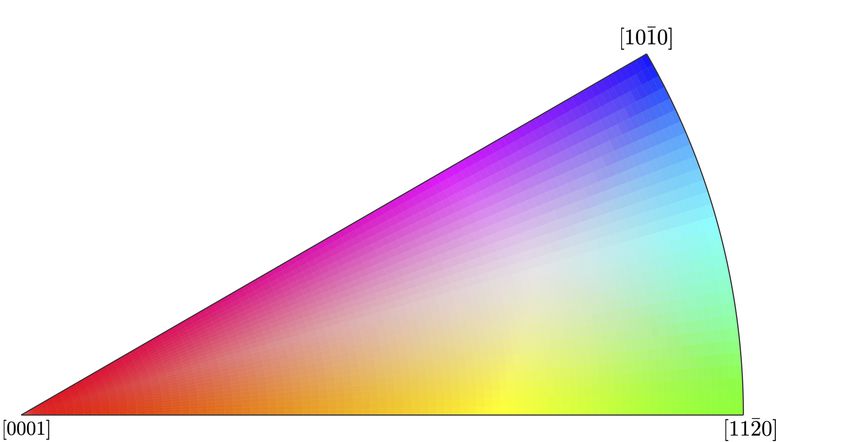
[13, 14, 15], fatigue crack initiation and growth [16, 17, 18, 19, 20, 21], or post mortem characterization of
fatigue failure [22]. However, fatigue can occur below the macroscopic yield stress, indicating that plasticity
must be occurring in smaller amounts on lower length scales. Thus, this work focuses on the novel approach
of using synchrotron x-rays to track the micromechanical and texture evolution of an experimental 3D
microstructure with a hexagonal crystal structure being cyclically loaded below its macroscopic yield stress.
   High energy x-ray diffraction microscopy (HEDM) is a synchrotron x-ray, rotating crystal technique
used for micromechanical and microstructural characterization of materials in three dimensions. One of the
major advantages to using this technique is its non-destructive nature which enables us to perform in situ
experiments to study material evolution. In particular, far-field high energy x-ray diffraction microscopy
(ff-HEDM) can be used to measure the grain-averaged elastic strain tensor, grain averaged-orientation, and
center of mass for each of the grains in each state of a specimen [23, 24]. More specifics on this technique
can be found in Bernier et al. [25]. Significant previous studies utilizing the HEDM technique have been
reported on the Ti-7Al material being studied here [26, 27, 28, 29, 30, 31, 32, 33, 34]. Ti-7Al a model
alloy for the hexagonal α-phase of the titanium alloy Ti-6Al-4V which is commonly used in aerospace and
biomedical applications. The combination of a relatively high flow strength and relatively compliant elastic
response lead to large elastic strains that are easily observable with diffraction; that, combined with the
ability to process a microstructure with large, pristine grains make Ti-7Al an ideal material for ff-HEDM
studies.
   Plastic deformation in Ti-7Al is accommodated on slip systems of varying strengths which are denoted
in Figure 1 and Table 1 [35, 7, 36, 37, 26, 32, 38]. As seen in Table 1, the prismatic hai system has the lowest
critical resolved shear stress (CRSS) followed by the basal hai system then the pyramidal hai system. Thus,
grains oriented to activate hai slip will preferentially slip on the prismatic hai systems. In order to close the
yield surface, slip may also occur on the pyramidal hc+ai systems. When slip occurs on a single slip system,
the axis about which the grain rotates, Ω, can be calculated using b×n where b is the slip direction, and
n is the slip plane normal (Table 1). Consequently, this reorientation axis can indicate which slip system
is active when a grain’s change in orientation is known. However, this only works for the case where a
single slip system is being activated in a grain. When multiple slip occurs, the axis is less useful because it
becomes more difficult to separate out the effects of individual slip systems without knowing their separate
contributions. Furthermore, the addition of > 5 wt% of aluminum to titanium encourages the formation of
short range order and α2 Ti3 Al nanoprecipitates, which have previously been observed in Ti-7Al [39]. In
turn, these suppress twinning and give the slip systems their strength [40, 41, 42, 43, 39, 44]. Subsequent
shearing of the α2 from dislocation movement causes these slip systems to soften [32].
   In this work, ff-HEDM is used to measure the evolution of the micromechanical and microstructural
state of grains, individually and as an ensemble, in a sample of Ti-7Al through 200 loading cycles.

                                                       2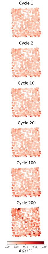
Slip System                      b           n            Ω          CRSS (MPa) [32]
                         Prismatic hai               h12̄10i       {101̄0}     h0001i                 248
                             Basal hai               h12̄10i       {0001}      h101̄0i                253
                        Pyramidal hai                h112̄0i       {11̄01}     h011̄2i                255
                 1st Order Pyramidal hc+ai           h1̄1̄23̄i     {11̄01}    h13 8̄ 5̄ 3̄i           270
                2nd Order Pyramidal hc+ai            h1̄1̄23̄i     {112̄2}     h11̄00i

Table 1: The family of slip directions b, family of slip plane normals, n, and familes of reorientation axes, Ω and the critical
resolved shear stress (CRSS) for the five major slip systems for the hexagonal crystal system.

2. Experiment

    The Ti-7Al material for this experiment was cast as an ingot, hot isostatic pressed to eliminate porosity,
extruded, heat treated at 962 ◦ C for 24 hours, then air cooled to form large equiaxed grains [45]. A
sample was subsequently electrically discharged machined (EDM) from the bulk material, which left behind
a notable amount of grain scale residual strains around the surface of the gauge section as shown in Figure
5c. The microstructure of the region of interest in this work is shown in Figure 2b with accompanying pole
figures to detail the texture of the sample is in Figure 2a which shows that the c-axes lie predominantly

                                (a) Prismatic hai             (b) Basal hai       (c)     Pyramidal
                                                                                  hai

                                          (d) 1st Order               (e) 2nd Order
                                          Pyramidal hc+ai             Pyramidal hc+ai

Figure 1: The five major slip systems for the hexagonal crystal system marked with the slip plane normal, n, slip direction, b,
and reorientation axis, Ω.

                                                                  3
(a)

                                                             (b)

Figure 2: (a) Contour pole figures showing that the c-axes lie mostly perpendicular to the tensile axis. (b) The nf-HEDM volume
(IPF coloring with respect to the loading direction) was reconstructed using HEXRD from the grain-averaged orientations found
in the ff-HEDM data.

perpendicular to the tensile axis.
    Tensile cycles (R=0) to 585 MPa (∼90 % of yield) were performed in load control on a sample of Ti-
7Al using the RAMS2 load frame [46] at the F2 beamline at the Cornell High Energy Synchrotron Source
(CHESS) with the geometry shown in Figure 3. The sample had an 8mm gauge length and a 1 mm x 1 mm
cross-sectional area. Near-field and far-field HEDM scans were taken in the initial unloaded state. Then,
the sample was loaded to 585 MPa and unloaded to 505 MPa to minimize stress relaxation during ff-HEDM
measurements, and another ff-HEDM scan was taken over the same approximate volume. The sample was
unloaded back to 0 N, and a final ff-HEDM scan was taken (Fig. 4a). This process was repeated at cycles
2, 5, 10, 20, 30, and every 10 cycles until a total of 200 cycles was reached.
    The ff-HEDM scans were taken for a full 360◦ sweep at an ω interval of 0.25◦ using an energy of 61.3
keV. For these scans, data was collected for a 1 mm tall volume in six 60◦ wedges using a GE amorphous
silicon area detector (2048 x 2048 pixels, 200 µm pixel size). Reduction of the ff-HEDM data was done using
the HEXRD package (https://github.com/HEXRD/hexrd) [23]. The diffraction was fit to obtain the grain
averaged orientation (g), center of mass, and elastic strain tensor (ε). The reduced data was filtered with a

                                                              4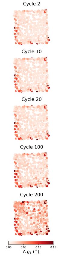
Figure 3: Schematic of the ff-HEDM experimental setup at CHESS marked where ω is the rotation angle of the sample, and η
is the azimuthal coordinate on the detector, and 2θ is the diffraction angle.

                                 (a)                                                   (b)

Figure 4: (a) The cyclic macroscopic stress-strain curves was calculated using DIC for the first load cycle with the points
marked where ff-HEDM scans were taken. (b) The cyclic stress-strain curves for the 1st, 2nd, 100th, and 200th cycles are
shown with some plasticity occurring during the first cycle and the other cycles showing a mostly elastic response.

threshold of normalized sum of square residuals < 2 × 10⁻³ which left 502 of the original 773 grains to be
used for analysis [25]. Then, the stress tensor, σ, was calculated from the single crystal stiffness tensor, C,
[47, 32] and the elastic strain tensor for each of the grains in each scan using σij = Cijkl εkl .

3. Results

    For the macroscopic stress-strain response shown in Figure 4b, the macroscopic strain was measured
using digital image correlation performed on optical images of the sample surface and macroscopic stress
was calculated from a load cell placed above the specimen. The unloading curve for the first cycle has shifted
slightly from the loading for that cycle showing that some plasticity occurred, while the curve for the second
cycle exhibits a stable elastic response that lies on top of the unloading of the first cycle. By the 100th cycle,
                                                               5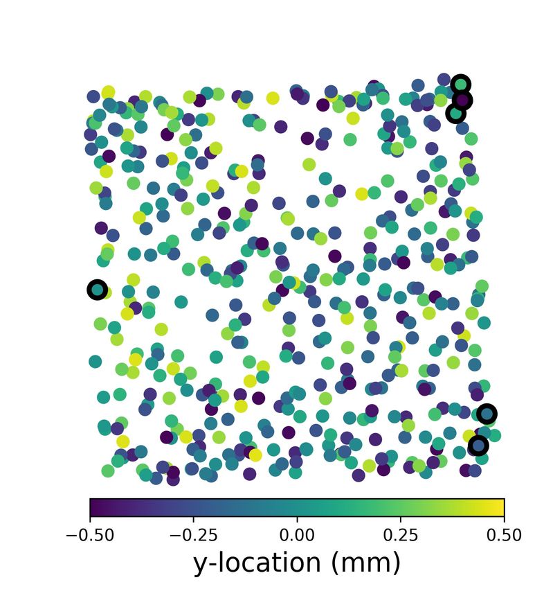
the curve has shifted just slightly, and the 200th cycle has shifted slightly more showing small amounts of
plasticity occurring over the course of each 100 cycles.

3.1. First Cycle

   On the grain level, the spread of the distribution of the strain in the loading direction (εyy ) can be
analyzed using a normal probability plot which compares the data to a normal distribution and would
be represented by a straight line. Figure 5a shows that while cycles 1, 2, and 5 appear to be reasonably
approximated by the same distribution, the initial state is significantly different. The tail on the initial
distribution means that a portion of the grains have an initial strain higher than expected by the bulk of
the distribution. In Figure 5b, the histograms of εyy show a shift from a peak at a negative strain to a peak
at zero. The spatial distribution of this change can be seen in Figure 5c where in the initial state, grains
on the outer surface have a tensile εyy while the inner grains have a compressive εyy . Then, after the first
cycle, the spatial heterogeneity of strain has been eliminated via dislocation activity in the surface grains
and the strain values are more nearly randomly distributed. Further supporting the evidence of surface
grains yielding during the first cycle, in Figure 5d, the grains with the largest change in orientation are on
the surface of the sample.

3.2. Evolution of Measured Quantities

   Von Mises equivalent stress (σV M ) is often used to determine when a ductile metal will yield. In the
normal probability plot for the σV M distribution shown in Figure 6, the linear nature of the curve indicates
a normal distribution. The rotation of the line through increasing cycles indicates that the distribution of
σV M is broadening as a function of cycle number (i.e. an increasing number of higher stress grains and lower
stress grains). Additionally, the median value is increasing (slightly) through the cycles.
   Grain rotations were calculated from the grain-averaged orientations to serve as a surrogate method
for observing slip events. The normal probability plot in Figure 7 displays the change in grain orientation
relative to initial grain orientation and shows that an increasing fraction of the grains have larger change
in grain-averaged orientation (∆g) as cycles accumulate. Figure 7a is for ∆g0 , the change in orientation
from the initial unloaded state while Figure 7b is for ∆g1 , the change in orientation from the unloaded state
after the first cycle. Note that the uncertainty in change in orientation from scan to scan is estimated as
approximately 0.003-0.005◦ , and is further addressed in Section 4.
   In addition to looking at σV M and ∆g, the stress tensor for each grain, σgrain , can be compared to the
macroscopic stress tensor, σmacro . Stress coaxiality angle, φmacro relates the stress state of an individual
grain to the macroscopic applied load and can be calculated as:

                                              −1    σmacro : σgrain
                                  φmacro = cos                          .                                 (1)
                                                   kσmacro kkσgrain k

                                                      6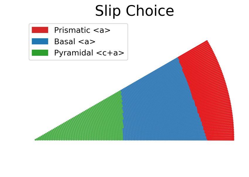
(a) (b)
(c)
(d)
Figure 5: (a) The normal probability distribution of εyy shows a change in the distribution from the initial state to the states
after 1, 2, and 5 cycles. (b) The histogram of εyy shift towards 0 during the first cycle. (c) εyy is plotted according to the
distribution in the x-z plane with color corresponding to the magnitude of the strain. (d) The grains with the largest ∆g after
the first cycle are located on the surface of the sample. The grains with the smallest φinit are also on the surface of the sample.
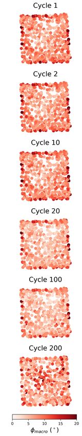
A low φmacro indicates that a grain is well aligned with the the macroscopic stress tensor. In Figure
8a, φmacro evolves with the number of cycles with the bulk grains having better alignment of their grain
stress tensors with the macroscopic stress tensor than the surface grains until cycle 100. By cycle 200, the
distribution of grains with high and low φmacro are distributed throughout the sample showing no preference
7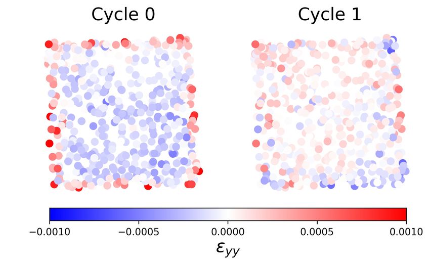
Figure 6: The von Mises stress in the loaded state shows a rotation in the probability distribution around the 30% value
indicating that the distribution is spreading out and the median increases slightly but steadily with the accumulation of cycles.

for the surface or bulk. Figure 8b shows that ∆g0 from the initial orientation is negligible during the first
100 cycles, but by the 200th cycle, there is a general increase in ∆g0 across the entire sample.
    The coaxiality angle can also be calculated with respect to each grains’ initial unloaded stress state,
 0
σgrain ,   rather than the macroscopic applied stress:
                                                                                  !
                                                               0
                                                       −1
                                                              σgrain  : σgrain
                                          φinit = cos          0                      .                                      (2)
                                                             kσgrain kkσgrain k

In this case, φinit is a measure of the how well aligned a grain’s stress tensor is with its stress tensor in
the initial state. Due to the major changes in stress and orientation that occurred during the first cycle,
the subsequent unloaded states were compared to the sample state after the first cycle. As the number of
cycles increases in Figure 8c, the coaxiality angle increases, indicating that the stress tensor of each grain is
becoming less and less aligned with its initial stress tensor. In Figure 8d, the 2nd cycle has little change in
orientation from after the first cycle, but, again, by the 200th cycle, ∆g1 has generally increased across the
grain ensemble.

3.3. Grain Rotations

    Investigating the outlier grains further, the six grains with ∆g0 > 0.15◦ are marked in Figure 9a, and
are clearly all located on the surface of the sample. When the orientations for these grains are plotted for
each of the cycles in Figure 9b-g, it becomes evident that all six of of the grains are rotating such that their
c-axis points away from the loading direction. In following that line of thought, the grains with ∆g0 > 0.05◦
are plotted on an IPF triangle in Figure 10 with the direction of the arrow indicating the direction of the
grain rotation and the length of the arrow equaling 10x the magnitude of ∆g0 .
                                                               8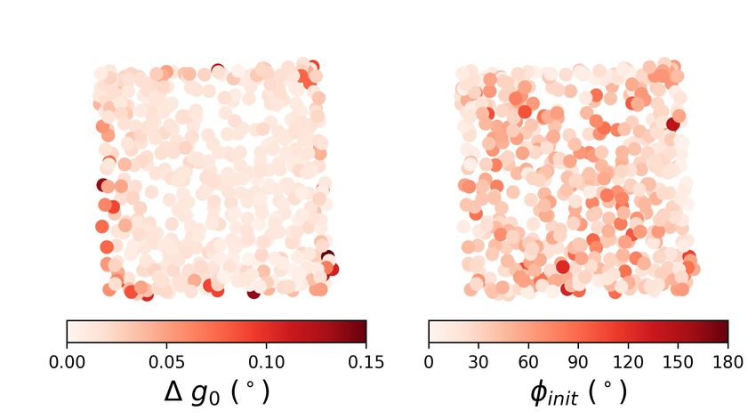
(a)                                                              (b)

Figure 7: (a) A probability distribution at each of the unloaded states was plotted for ∆g0 , the change in orientation from the
initial unloaded state. (b) A probability distribution was plotted for ∆g1 , the change in orientation from the orientation after
the first cycle to the other unloaded states in order to remove initial change from the yielding of the surface grains during the
initial cycle. As the number of cycles increases, the distribution moves such that more grains have a higher ∆g.

4. Discussion

4.1. Aggregate Evolution

    The tensile strains present in the initial state seen in Figure 5c can be attributed to the recast layer from
the EDM [48]. Not only does this speak to the precision of the measurements in this dataset, but also causes
some interesting behavior for the first cycle. The residual strain present along the surface of the sample
in the initial state goes away after the first cycle indicating that the grains with high residual yy yielded
during the first cycle, thereby relieving their residual strain (and stress).
    Orientation precision for the values in Figures 5d, 7, 8b, 9, and 10 can be considered to be ∼0.003◦ based
on Bernier et al. [23]. However, this value is based on a series of ruby scans done for only a 120◦ sweep
rather than the 360◦ sweep done here, thus the uncertainty in orientation is likely to be even smaller than
∼0.003◦ for the full rotation. Work is being pursued on a new set of ruby experiments with a variety of
experimental parameters, including a full 360◦ sweep, in order to refine the determination of the precision
of ff-HEDM experimental results with current instrumentation and setup.
    As grains slip, they rotate to accommodate the slight changes in shape and stress state, and lattice
rotation will occur subsequently to maintain compatibility, thus, grain rotation can be used as a proxy for
slip. Consequently, as grains continue to slip through subsequent cycles, the grain rotation serves as an
indicator of the accumulation of plastic strain and possibly damage in a grain. This is significant as the
sample was being cycled at only 90 % of its yield stress (Fig. 4) and consistently exhibited macroscopic elastic

                                                               9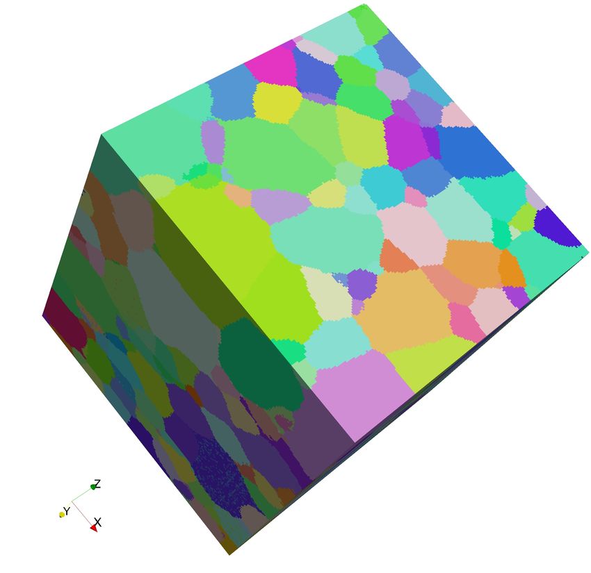
(a)                       (b)                           (c)                          (d)

Figure 8: In the loaded state, (a) φmacro decreases with increasing cycles until cycle 100 with the surface grains having a
higher φmacro . After cycle 100, the grains with high φmacro are distributed throughout the sample. (b) As with the unloaded
state, in the loaded state, the grain-averaged orientations show a larger ∆g from the initial loaded orientation during the 200th
cycle than during the 1st. In the unloaded state, (c) the coaxiality angle with respect to the stress tensor after the first cycle
increases through the cycles. (d) The grain-averaged orientation is more misoriented from the initial orientation after the 200th
cycle than after the 1st.

                                                               10
behavior with negligible hysteresis. Therefore, although the sample appeared to deform only elastically from
a macroscopic perspective, changes in stress state and orientation were occurring heterogeneously in the
individual grains. In the absence of nucleation at microstructural heterogeneities such as voids and brittle
particles, single phase metals typically form fatigue cracks at slip steps or grain boundaries. The significance
of the continual slip is therefore that it leads to the build-up of damage that drives the initiation and growth
of fatigue cracks and eventually failure. Another way to state this is that irreversible dislocation motion
(a)
(b) Grain 166 (c) Grain 167 (d) Grain 347
(e) Grain 62 (f) Grain 66 (g) Grain 148
Figure 9: (a) Location of the grain COMs in the x-z plane colored according to their location in the y-dimension marked with
the six grain with the largest change in grain-averaged orientation (∆g0 ). (b-g) The six grains rotate so that their c-axis points
further away from the loading direction. ∆g is greater during the first cycle than any of the subsequent ones.
11Figure 10: IPF triangle for the loading axis plotted with arrows pointing in the direction of the orientation change (at 10× the
magnitude of change) for grains with > 0.05◦ of orientation change from the initial state to the final state.
occurred on a microscopic scale in a majority of grains.
Accordingly, the upper tails of the distributions of ∆g, defined here as having > 0.01◦ change in orienta-
tion when compared to the orientation after the first cycle, were analyzed using extreme value statistics. The
Fisher-Tippett-Gnedenko theorem [49, 50] states that the probability distribution function for a convergent
generalized extreme value distribution will fit one of three distributions: Gumbel [51, 52], Fréchet [53], or
Weibull [54]. These three distributions were fit to the upper tails of ∆g, and Figure 11 shows the R2 values
for the fits at different cycle numbers and reveals that the Fréchet distribution (Eq. 3) consistently fits the
tail better than the other two. The Fréchet probability distribution function has form:
α−1 α
α β β
f (x) = exp − (3)
β x−γ x−γ
where α > 0 is the shape parameter, β > 0 is the scale parameter, and γ is the location parameter. The
fit for the last 50 cycles was averaged and found to be α = 0.952, β = 0.018, and γ = 0.010. This analysis
clarifies that the distribution of plastic strain, as detected by the orientation change was far from Gaussian
and exhibited a heavy upper tail. This indicates that a minority of grains experienced much larger plastic
behavior than the rest, which helps us to understand how fatigue crack initiation is an extreme event [55, 56].
To the authors’ knowledge, this is the first time that the heterogeneity of slip accumulation under nominally
elastic cyclic loading has been quantified to this level of detail.
12Figure 11: The three extreme value distributions were fit to the upper tail of the ∆g probability distributions, and the Fréchet
distribution consistently fits the best.
4.2. Grain Rotations and Slip
The six grains with the largest changes in orientation are oriented such that the basal hai and/or pyra-
midal hc+ai systems are activating and rotate in the direction that increases the angle between their c-axis
and the loading direction (Fig. 9). This rotation orients the grains in such a way as to promote prismatic
hai slip, the softest of the systems available for deformation in Ti-7Al. As a whole, the grains in the sample
are rotating in such a way that a tension texture begins to develop [57, 58, 59, 60, 61], albeit the process is
in its early stages. Throughout the sample, the grains near [0001] are slipping on basal hai and pyramidal
hc+ai systems and rotating so that the [0001] axis points away from the loading direction. Additionally,
the grains far from [0001] are slipping on the prismatic hai system and rotating so that the [101̄0] direction
becomes more aligned to the loading direction.
The CRSS (see Table 1) for each slip system was divided by the Schmid factor at a given orientation
to show the uniaxial stress required to activate each of the slip systems relative to a grain’s orientation. It
is also important to note, however, that no grain will be in a purely uniaxial stress state, but this analysis
gives an idea of what is generally occurring. As can be seen in Figure 12, the grains oriented on the right
side of the triangle with [0001] far from the loading direction require a lower stress to activate the prismatic
hai slip systems while the grains with orientations in the middle of the triangle are more likely to slip on the
basal hai family. Moreover, the pyramidal hc+ai systems must activate for the grains oriented with their
c-axis parallel to the loading direction. The pyramidal hai is not shown since it is rarely observed [62].
The uniaxial stresses in Figure 12 are taken and combined into one triangle to better show the likely slip
system to be activated at a given orientation. However, the slip rate dependence and slip system strength
evolution are not taken into account by the CRSS which assumes rate independent plasticity. In terms of
rate sensitivity, Beausir et al. [63] calculated that the the prismatic hai and basal hai systems have a higher
rate sensitivity, which functionally means that they slip more easily at low stresses, than the pyramidal hc+ai
13(a) (b)
(c)
Figure 12: (a-c) The CRSS for each slip system was divided by the maximum Schmid factor at a given orientation on the
fundamental triangle to give the uniaxial stress required to activate the slip system at that orientation.
slip systems. Additionally, Pagan et al. [32] found that the pyramidal hc+ai slip systems harden rapidly
while the prismatic hai and basal hai systems soften. It was also noted that the CRSS values for the basal
hai and pyramidal hc+ai slip systems reported in Pagan et al. are lower than those reported for titanium
alloys with similar aluminum content (Ti-6.7Al) [35, 64]. The slip choice triangle was adjusted based on this
rationale and recalculated with higher CRSS values (Table 2) for the basal hai and pyramidal hc+ai slip
systems yielding the result in Figure 13. In light of these adjustments, Figure 10 can be reexamined with
respect to the slip system preferences in Figure 13. As stated previously the grains with orientations on the
right side of the triangle which are indeed slipping on the prismatic slip systems and rotating around the
c-axis while the grains with orientations in the middle of the triangle are rotating so that their c-axis points
away from the loading direction.
4.3. Effect of Orientation on Micromechanics
The collection of grains was divided into three different categories according to the direction of their
grain rotation: grains with greater than 0.05◦ change in rotation which are rotating away from [0001], grains
14(a)
Figure 13: Each region of the fundamental triangle is colored according to the preferred slip system at that orientation based on
Schmid factor (Fig. 12) and the CRSS calculated in Pagan et al. [32]. The regions for the preferred slip systems were adjusted
to reflect slip choice based on understanding of hardening/softening behavior and slip rate sensitivity dependence [35, 63, 64].
Slip System CRSS from Pagan et al. Adjusted CRSS
Prismatic hai 248 MPa 248 MPa
Basal hai 253 MPa 293 MPa *
1st Order Pyramidal hc+ai 270 MPa 365 MPa **
* from May [64].
** average of May [64] and Pagan et al. [32].
Table 2: The CRSS as reported in Pagan et al. and the CRSS values adjusted for hardening behavior and rate dependence
used in Figure 13.
with greater than 0.05◦ change in rotation which are rotating away from [21̄1̄0], and grains with less than
0.05◦ change in rotation. The resolved shear stress (RSS) on each of the slip systems was calculated from
the grain averaged stress tensors and the maximum value was found for each grain for each family of slip
systems. Then, the average of these maximum values was found for each of the groups of grains and plotted
with respect to cycle number. In the case of the unloaded state in Figure 14, the grains with their c-axis
pointing close to the loading direction have higher RSS values than any of the other categories of grains.
These grains are in a “hard” orientation, which means they are more resistant to deformation. As such,
the higher RSS values for these grains indicate that they are accumulating more of the residual stress as
compared to the rest of the grains when the sample is unloaded.
15Figure 14: In the unloaded state, the maximum RSS values for each slip system for each grain were averaged and plotted for
each of the three categories of observed rotation behavior. The grains with the (0001) direction rotating away from the loading
direction have a higher RSS on all of the slip systems than the rest of the grains.
5. Summary
A sample of Ti-7Al was cycled 200 times at 90 % of its yield stress, and ff-HEDM scans were taken in
both the unloaded and loaded states for the 1st, 2nd, 5th, and 10th cycles, and every 10 cycles subsequently
(Fig. 4). EDM of the sample left residual strain that is evident in the initial state (Fig. 5). However, we were
able to resolve this residual strain and observed the high stress grains yielded during the first cycle. The
evolution of the grains through the 200 cycles reveals a continual change in von Mises stress and orientation
across the entire specimen (Figs. 6 and 7) indicating a slow accumulation of plasticity even though the sample
was cycled below its macroscopic yield. In the loaded state, the grain stress tensors become progressively
more aligned with the macroscopic stress tensor through increasing cycles (Fig. 8). Likewise, the grain
stress tensors in the unloaded states become progressively less aligned with their initial grain stress tensor
16after the initial cycle (Fig. 8b). The six grains with the largest change in orientation through the 200 cycles
all rotate such that their c-axes point further away from the loading direction (Fig. 9). In general, the grains
oriented with their c-axis more parallel to the loading direction slip on the basal planes and rotate away from
the [0001] direction, while the grains closer to [21̄1̄0] slip on the prismatic system and rotate away from the
[112̄0] direction (Fig. 10). This, in fact, matches predictions that can be made based on Schmid factor and
CRSS adjusted for hardening behavior and slip rate dependence. Overall, the pattern of grain reorientation
is consistent with the development of a tension texture despite the negligible magnitude of (macroscopic)
plastic strain. It was observed that the grains in a “hard” orientation (c-axis closer to the loading direction)
retain more residual stress on all of the slip systems upon unloading than the grains in a “soft” orientation
(Fig. 14). Lastly, the precision of grain-averaged orientation measurements from the ff-HEDM technique
permitted for the first time analysis of the upper tails of distributions of grain reorientation, which were
fit well by the Fréchet distribution: this quantification may provide input for the quantification of fatigue
crack initiation, see, e.g. Przybyla et al. [65].
Acknowledgements
The authors thank Adam Pilchak for providing the Ti-7Al material. They are also grateful to Christopher
Kantzos, He Liu, and Yu-Feng Shen for helping with the experiment. Joe Pauza, Vahid Tari, Sven Gustafson,
Jerard Gordon, and Bill Musinski are thanked for helpful discussions. This work is based upon research
conducted at the Cornell High Energy Synchrotron Source (CHESS) which was supported by the National
Science Foundation and the National Institutes of Health/National Institute of General Medical Sciences
under NSF award DMR-1332208. The work is funded by the Air Force Office of Scientific Research under
grant FA9550-16-1-0105.
17References
[1] K. Dang Van, I. Papadopoulus, High-cycle metal fatigue: From theory to applications (1999).
[2] A. Constantinescu, K. Dang Van, M. H. Maitournam, A unified approach for high and low cycle fatigue based on shakedown
concepts, Fatigue & Fracture of Engineering Materials & Structures 26 (2003) 561–568.
[3] E. Charkaluk, A. Constantinescu, H. Maitournam, K. Dang Van, Revisiting the Dang Van criterion, Procedia Engineering
1 (2009) 143–146.
[4] J. R. Mayeur, Three dimensional modeling of titanium-aluminum alloys with application to attachment fatigue, Ph.D.
thesis, Georgia Institute of Technology (2004).
[5] M. Zhang, J. Zhang, D. L. McDowell, Microstructure-based crystal plasticity modeling of cyclic deformation of Ti-6Al-4V,
International Journal of Plasticity 23 (2007) 1328–1348.
[6] B. D. Smith, D. S. Shih, D. L. McDowell, Cyclic plasticity experiments and polycrystal plasticity modeling of three distinct
Ti alloy microstructures, International Journal of Plasticity 101 (2018) 1–23.
[7] X. Tan, H. Gu, C. Laird, N. D. H. Munroe, Cyclic deformation behavior of high-purity titanium single crystals: Part I.
Orientation dependence of stress-strain response, Metallurgical and Materials Transactions A 29 (1998) 507–512.
[8] X. Tan, H. Gu, C. Laird, N. D. H. Munroe, Cyclic deformation behavior of high-purity titanium single crystals: Part
II. Microstructure and Mechanism, Metallurgical and Materials Transactions A 29 (2) (1998) 507–512. doi:10.1007/
s11661-998-0131-0.
[9] L. Xiao, Y. Umakoshi, Orientation dependence of cyclic deformation behavior and dislocation structure in Ti-5at.% A1
single crystals, Materials Science and Engineering A 339 (1-2) (2003) 63–72. doi:10.1016/S0921-5093(02)00104-1.
[10] B. Clausen, T. Lorentzen, T. Leffers, Self-consistent modelling of the plastic deformation of F.C.C. polycrstals and its
implications for diffraction measurements of internal stresses, Acta Materialia 46 (9) (1998) 3087–3098. doi:10.1016/
S1359-6454(98)00014-7.
[11] Y. D. Wang, H. Tian, A. D. Stoica, X. L. Wang, P. K. Liaw, J. W. Richardson, The development of grain-orientation-
dependent residual stresses in a cyclically deformed alloy, Nature Materials 2 (2) (2003) 101–106. doi:10.1038/nmat812.
[12] L. L. Zheng, Y. F. Gao, Y. D. Wang, A. D. Stoica, K. An, X. L. Wang, Grain orientation dependence of lattice strains
and intergranular damage rates in polycrystals under cyclic loading, Scripta Materialia 68 (5) (2013) 265–268. doi:
10.1016/j.scriptamat.2012.10.033.
[13] M. Obstalecki, S. L. Wong, P. R. Dawson, M. P. Miller, Quantitative analysis of crystal scale deformation heterogeneity
during cyclic plasticity using high-energy X-ray diffraction and finite-element simulation, Acta Materialia 75 (2014) 259–
272.
[14] S. L. Wong, M. Obstalecki, M. P. Miller, P. R. Dawson, Stress and deformation heterogeneity in individual grains within
polycrystals subjected to fully reversed cyclic loading, Journal of the Mechanics and Physics of Solids 79 (2015) 157–185.
[15] R. Carson, M. Obstalecki, M. P. Miller, P. R. Dawson, Characterizing heterogeneous intragranular deformations in poly-
crystalline solids using diffraction-based and mechanics-based metrics, Modelling and Simulation in Materials Science and
Engineering 25 (2017) 055008.
[16] M. Herbig, A. King, P. Reischig, H. Proudhon, E. M. Lauridsen, J. Marrow, J. Y. Buffire, W. Ludwig, 3-D growth of a
short fatigue crack within a polycrystalline microstructure studied using combined diffraction and phase-contrast X-ray
tomography, Acta Materialia 59 (2) (2011) 590–601. doi:10.1016/j.actamat.2010.09.063.
[17] J. Oddershede, B. Camin, S. Schmidt, L. P. Mikkelsen, H. O. Sørensen, U. Lienert, H. F. Poulsen, W. Reimers, Measuring
the stress field around an evolving crack in tensile deformed Mg AZ31 using three-dimensional X-ray diffraction, Acta
Materialia 60 (8) (2012) 3570–3580. doi:10.1016/j.actamat.2012.02.054.
[18] H. Proudhon, J. Li, W. Ludwig, A. Roos, S. Forest, Simulation of Short Fatigue Crack Propagation in a 3D Experimental
Microstructure, Advanced Engineering Materials 19 (8) (2017) 1–9. doi:10.1002/adem.201600721.
18[19] D. Naragani, M. D. Sangid, P. A. Shade, J. C. Schuren, H. Sharma, J. S. Park, P. Kenesei, J. V. Bernier, T. J. Turner,
I. Parr, Investigation of fatigue crack initiation from a non-metallic inclusion via high energy x-ray diffraction microscopy,
Acta Materialia 137 (2017) 71–84.
[20] A. Rovinelli, M. D. Sangid, H. Proudhon, Y. Guilhem, R. A. Lebensohn, W. Ludwig, Predicting the 3D fatigue crack
growth rate of small cracks using multimodal data via Bayesian networks: In-situ experiments and crystal plasticity
simulations, Journal of the Mechanics and Physics of Solids 115 (2018) 208–229. doi:10.1016/j.jmps.2018.03.007.
[21] D. P. Naragani, P. A. Shade, P. Kenesei, H. Sharma, M. D. Sangid, X-ray characterization of the micromechanical
response ahead of a propagating small fatigue crack in a Ni-based superalloy, Acta Materialia 179 (2019) 342–359. doi:
10.1016/j.actamat.2019.08.005.
[22] A. D. Spear, S. F. Li, J. F. Lind, R. M. Suter, A. R. Ingraffea, Three-dimensional characterization of microstructurally small
fatigue-crack evolution using quantitative fractography combined with post-mortem X-ray tomography and high-energy
X-ray diffraction microscopy, Acta Materialia 76 (2014) 413–424. doi:10.1016/j.actamat.2014.05.021.
[23] J. V. Bernier, N. R. Barton, U. Lienert, M. P. Miller, Far-field high-energy diffraction microscopy: a tool for intergranular
orientation and strain analysis, The Journal of Strain Analysis for Engineering Design 46 (2011) 527–547.
[24] J. Oddershede, S. Schmidt, H. F. Poulsen, H. O. Sørensen, J. Wright, W. Reimers, Determining grain resolved stresses in
polycrystalline materials using three-dimensional X-ray diffraction, Journal of Applied Crystallography 43 (2010) 539–549.
[25] J. Bernier, R. Suter, A. D. Rollett, J. Almer, High energy diffraction microscopy in materials science, Annual Reviews in
Materials Research 50 (1) (2020) 395–436.
[26] U. Lienert, M. C. Brandes, J. V. Bernier, J. Weiss, S. D. Shastri, M. J. Mills, M. P. Miller, In situ single-grain peak profile
measurements on Ti 7Al during tensile deformation, Materials Science and Engineering A 524 (2009) 46–54.
[27] J. C. Schuren, P. A. Shade, J. V. Bernier, S. F. Li, B. Blank, J. Lind, P. Kenesei, U. Lienert, R. M. Suter, T. J. Turner,
D. M. Dimiduk, J. Almer, New opportunities for quantitative tracking of polycrystal responses in three dimensions,
Current Opinion in Solid State and Materials Science 19 (2015) 235–244.
[28] K. Chatterjee, A. Venkataraman, T. Garbaciak, J. Rotella, M. D. Sangid, A. J. Beaudoin, P. Kenesei, J. S. Park, A. L.
Pilchak, Study of grain-level deformation and residual stresses in Ti-7Al under combined bending and tension using high
energy diffraction microscopy (HEDM), International Journal of Solids and Structures 94-95 (2015) 35–49.
[29] A. J. Beaudoin, P. A. Shade, J. C. Schuren, T. J. Turner, C. Woodward, J. V. Bernier, S. F. Li, D. M. Dimiduk, P. Kenesei,
J.-S. Park, Bright x-rays reveal shifting deformation states and effects of the microstructure on the plastic deformation of
crystalline materials, Physical Review B 96 (17) (2017) 174116. doi:10.1103/PhysRevB.96.174116.
[30] K. Chatterjee, J. P. Ko, J. T. Weiss, H. T. Philipp, J. Becker, P. Purohit, S. M. Gruner, A. J. Beaudoin, Study of residual
stresses in Ti-7Al using theory and experiments, Journal of the Mechanics and Physics of Solids 109 (2017) 95–116.
[31] T. J. Turner, P. A. Shade, J. V. Bernier, S. F. Li, J. C. Schuren, P. Kenesei, R. M. Suter, J. Almer, Crystal plasticity model
validation using combined high-energy diffraction microscopy data for a Ti-7Al specimen, Metallurgical and Materials
Transactions A 48 (2017) 627–647.
[32] D. C. Pagan, P. A. Shade, N. R. Barton, J. S. Park, P. Kenesei, D. B. Menasche, J. V. Bernier, Modeling slip system
strength evolution in Ti-7Al informed by in-situ grain stress measurements, Acta Materialia 128 (2017) 406–417.
[33] D. C. Pagan, J. V. Bernier, D. Dale, J. P. Ko, T. J. Turner, B. Blank, P. A. Shade, Measuring Ti-7Al slip system strengths
at elevated temperature using high-energy X-ray diffraction, Scripta Materialia 142 (2018) 96–100.
[34] K. Chatterjee, A. J. Beaudoin, D. C. Pagan, P. A. Shade, H. T. Philipp, M. W. Tate, S. M. Gruner, P. Kenesei, J.-S.
Park, Intermittent plasticity in individual grains: A study using high energy x-ray diffraction, Structural Dynamics 6 (1)
(2019) 014501. doi:10.1063/1.5068756.
[35] J. C. Williams, M. J. Blackburn, The identification of a non-basal slip vector in titanium and titanium-aluminum alloys,
Physica Status Solidi 25 (1968) K1–K3.
19[36] J. C. Williams, R. G. Baggerly, N. E. Paton, Deformation behavior of hcp Ti-Al alloy single crystals, Metallurgical and
Materials Transactions A 33 (2002) 837–850.
[37] G. Lutjering, J. C. Williams, Titanium, 2nd Edition, Springer-Verlag, 2007.
[38] V. Tong, E. Wielewski, B. Britton, Characterisation of slip and twinning in high rate deformed zirconium with electron
backscatter diffraction (2018). arXiv:1803.00236.
[39] A. Venkataraman, P. A. Shade, R. Adebisi, S. Sathish, A. L. Pilchak, G. B. Viswanathan, M. C. Brandes, M. J. Mills,
M. D. Sangid, Study of structure and deformation pathways in Ti-7Al using atomistic simulations, experiments, and
characterization, Metallurgical and Materials Transactions A 48 (2017) 2222–2236.
[40] T. Neeraj, M. J. Mills, Short-range order (SRO) and its effect on the primary creep behavior of a Ti - 6wt.% Al alloy,
Materials Science & Engineering A 321 (2001) 415–419.
[41] M. H. Yoo, J. R. Morris, K. M. Ho, S. R. Agnew, Nonbasal deformation modes of HCP metals and alloys: Role of
dislocation source and mobility, Metallurgical and Materials Transactions A: Physical Metallurgy and Materials Science
33 (3) (2002) 813–822. doi:10.1007/s11661-002-0150-1.
[42] A. Van de Walle, M. Asta, First-principles investigation of perfect and diffuse antiphase boundaries in HCP based Ti-Al
alloys, Metallurgical and Materials Transactions A 33 (2002) 735–741.
[43] A. Fitzner, J. Quinta da Fonseca, J. Kelleher, M. Pascal, D. G. L. Prakash, M. Thomas, S.-Y. Zhang, M. Preuss, The
effect of aluminium on twin activity in binary α-Ti, Acta Materialia 103 (2016) 341–351.
[44] H. M. Gardner, A. Radecka, D. Rugg, D. E. J. Armstrong, M. P. Moody, P. A. J. Bagot, A study of the interaction of
oxygen with the α 2 phase in the model alloy Ti 7wt % Al, Scripta Materialia 185 (2020) 111–116.
[45] A. L. Pilchak, Fatigue crack growth rates in alpha titanium: faceted vs. striation growth, Scripta Materialia 68 (2013)
277–280.
[46] P. A. Shade, B. Blank, J. C. Schuren, T. J. Turner, P. Kenesei, K. Goetze, R. M. Suter, J. V. Bernier, S. F. Li, J. Lind,
U. Lienert, J. Almer, A rotational and axial motion system load frame insert for in situ high energy x-ray studies, Review
of Scientific Instruments 86 (2015) 093902.
[47] E. S. Fisher, C. J. Renken, Single-crystal elastic moduli and the hcp to bcc transformation in Ti, Zr, and Hf, Physical
Review 135 (2A).
[48] P. Srinivasa Rao, K. Ramji, B. Satyanarayana, Effect of wire EDM conditions on generation of residual stresses in machining
of aluminum 2014 T6 alloy, Alexandria Engineering Journal 55 (2) (2016) 1077–1084.
[49] R. A. Fisher, L. H. C. Tippett, Limiting forms of the frequency distribution of the largest or smallest member of a sample,
Mathematical Proceedings of the Cambridge Philosophical Society 24 (2) (1928) 180190. doi:10.1017/S0305004100015681.
[50] B. Gnedenko, Sur la distribution limite du terme maximum d’une serie aleatoire, Annals of Mathematics 44 (3) (1943)
423–453.
[51] E. J. Gumbel, Les valeurs extrêmes des distributions statistiques, Annales de l’institut Henri Poincaré 5 (2) (1935) 115–158.
[52] E. J. Gumbel, Statistics of extremes, Courier Corporation, 2012.
[53] M. Fréchet, Sur la loi de probabilité de l’écart maximum, Ann. Soc. Math. Polon. 6 (1927) 93–116.
[54] W. Weibull, A Statistical Distribution Function of Wide Applicability, Journal of Applied Mechanics 13 (1951) 293–297.
[55] Z. P. Bazant, Probabilistic Mechanics of Quasibrittle Structures: Strength, Lifetime, and Size Effect, 1st Edition, Cam-
bridge University Press, 2017.
[56] E. Castillo, A. Hadi, N. Balakrishnan, J. Sarabia, Extreme Value and Related Models with Applications in Engineering
and Science, Wiley Series in Probability and Statistics, Wiley, Hoboken, 2004.
[57] F. Kocks, C. Tom, H.-R. Wenk, Texture and Anisotropy. Preferred Orientations in Polycrystals and Their Effect on
Material Properties, Cambridge University Press, 2000.
[58] B. Kouchmeshky, N. Zabaras, Modeling the response of HCP polycrystals deforming by slip and twinning using a finite
20element representation of the orientation space, Computational Materials Science 45 (4) (2009) 1043–1051. doi:10.1016/
j.commatsci.2009.01.009.
[59] S. Y. Huang, S. R. Zhang, D. Y. Li, Y. H. Peng, Simulation of texture evolution during plastic deformation of FCC,
BCC and HCP structured crystals with crystal plasticity based finite element method, Transactions of Nonferrous Metals
Society of China (English Edition) 21 (8) (2011) 1817–1825. doi:10.1016/S1003-6326(11)60936-9.
[60] J. Lind, In-Situ High Energy Diffraction Microscopy Study of Zirconium Under Uni-axial Tensile Deformation, Ph.D.
thesis, Carnegie Mellon University (2013).
[61] A. Chapuis, Q. Liu, Simulations of texture evolution for HCP metals: Influence of the main slip systems, Computational
Materials Science 97 (2015) 121–126. doi:10.1016/j.commatsci.2014.10.017.
[62] F. Bridier, P. Villechaise, J. Mendez, Slip and fatigue crack formation processes in an α/β titanium alloy in relation to
crystallographic texture on different scales, Acta Materialia 56 (15) (2008) 3951–3962. doi:10.1016/j.actamat.2008.04.
036.
[63] B. Beausir, L. S. Tóth, K. W. Neale, Role of strain-rate sensitivity in the crystal plasticity of hexagonal structures,
International Journal of Plasticity 23 (2) (2007) 227–243. doi:10.1016/j.ijplas.2006.02.013.
[64] K. May, Small Scale Tensile Testing of Titanium Alloys, Ph.D. thesis, The Ohio State University (2010).
[65] C. P. Przybyla, D. L. McDowell, Microstructure-sensitive extreme-value probabilities of high-cycle fatigue for surface vs.
subsurface crack formation in duplex ti-al-4v, Acta materialia 60 (1) (2012) 293–305.
21You can also read