Quartz dissolution associated with magnesium silicate hydrate cement precipitation
←
→
Page content transcription
If your browser does not render page correctly, please read the page content below
Solid Earth, 12, 389–404, 2021
https://doi.org/10.5194/se-12-389-2021
© Author(s) 2021. This work is distributed under
the Creative Commons Attribution 4.0 License.

Quartz dissolution associated with magnesium silicate
hydrate cement precipitation
Lisa de Ruiter1,z , Anette Eleonora Gunnæs2 , Dag Kristian Dysthe1 , and Håkon Austrheim1
1 Physics of Geological Processes (PGP), The Njord Centre, Department of Geosciences and Department of Physics,
University of Oslo, P.O. Box 1048, Blindern, 0136 Oslo, Norway
2 Centre for Materials Science and Nanotechnology, Department of Physics, University of Oslo,

P.O. Box 1048, Blindern, 0136 Oslo, Norway
z Invited contribution by Lisa de Ruiter, recipient of the EGU Geochemistry, Mineralogy, Petrology & Volcanology

Outstanding Student Poster and PICO Award 2018.

Correspondence: Håkon Austrheim (h.o.austrheim@geo.uio.no)

Received: 15 March 2020 – Discussion started: 31 March 2020
Revised: 29 November 2020 – Accepted: 16 December 2020 – Published: 18 February 2021

Abstract. Quartz has been replaced by magnesium silicate            1   Introduction
hydrate cement at the Feragen ultramafic body in south-east
Norway. This occurs in deformed and recrystallized quartz
                                                                    Weathering at the Earth’s surface leads to the breakdown of
grains deposited as glacial till covering part of the ultra-
                                                                    rocks and the release of chemical compounds to the weath-
mafic body. Where the ultramafic body is exposed, weath-
                                                                    ering fluids and is consequently an important process for the
ering leads to high-pH (∼ 10), Mg-rich fluids. The dissolu-
                                                                    chemical cycle of elements and the chemistry of groundwa-
tion rate of the quartz is about 3 orders of magnitude higher
                                                                    ter and soil. The released compounds could also lead to new
than experimentally derived rate equations suggest under the
                                                                    chemical sediment through the precipitation of secondary
prevailing conditions. Quartz dissolution and cement precip-
                                                                    minerals. Dissolution rates of silicate minerals have been
itation start at intergranular grain boundaries that act as fluid
                                                                    studied extensively, but there is a widely observed discrep-
pathways through the recrystallized quartz. Etch pits are also
                                                                    ancy between field and laboratory measurements. The ob-
extensively present at the quartz surfaces as a result of prefer-
                                                                    tained weathering rates of silicate minerals from field sam-
ential dissolution at dislocation sites. Transmission electron
                                                                    ples can vary by multiple orders of magnitude from experi-
microscopy revealed an amorphous silica layer with a thick-
                                                                    mentally obtained rates, with the latter usually being higher
ness of 100–200 nm around weathered quartz grains. We
                                                                    (White et al., 2001; White and Brantley, 2003; Brantley,
suggest that the amorphous silica is a product of interface-
                                                                    2005; Zhu et al., 2006; Moore et al., 2012). This indicates the
coupled dissolution–precipitation and that the amorphous sil-
                                                                    complexity of dissolution mechanisms in nature and the in-
ica subsequently reacts with the Mg-rich, high-pH bulk fluid
                                                                    ability to measure dissolution rates under these complex con-
to precipitate magnesium silicate hydrate cement, allowing
                                                                    ditions and timescales in the laboratory (Gruber et al., 2014).
for further quartz dissolution and locally a complete replace-
                                                                    Hellmann et al. (2012) concluded that chemical weather-
ment of quartz by cement. The cement is the natural equiv-
                                                                    ing of silicate minerals is controlled by nanoscale interfacial
alent of magnesium silicate hydrate cement (M-S-H), which
                                                                    dissolution–precipitation mechanisms and proposed a con-
is currently of interest for nuclear waste encapsulation and
                                                                    tinuum model for chemical weathering of silicates solely
for environmentally friendly building cement, but it has not
                                                                    based on dissolution and reprecipitation. The importance of
yet been developed for commercial use. This study provides
                                                                    this mechanism is supported by other experimental studies
new insights that could potentially contribute to the further
                                                                    showing the precipitation of amorphous silica on dissolv-
development of M-S-H cement.
                                                                    ing silicate mineral surfaces (Hellmann et al., 2003; Daval
                                                                    et al., 2011; Ruiz-Agudo et al., 2014, 2016). The presence

Published by Copernicus Publications on behalf of the European Geosciences Union.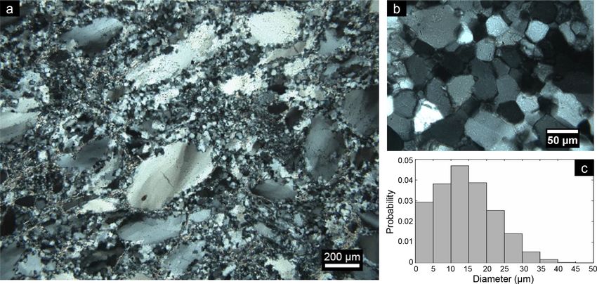
390                                                   L. de Ruiter et al.: Quartz dissolution and M-S-H cement precipitation

of such a layer has also been observed on weathered min-            quired to be able to manufacture M-S-H on a commercial
erals from field samples (Nugent et al., 1998; Zhu et al.,          scale. M-S-H cement is typically produced from reactive
2006; Velbel and Barker, 2008). The precipitated material           but expensive silica fume, an amorphous ultrafine powder of
could be initially amorphous but could also evolve into, for        SiO2 . The natural equivalent described here is formed from
example, clay minerals. The occurrence of this dissolution–         widely available natural quartz and the dissolution products
precipitation mechanism in nature could influence the disso-        of brucite. Understanding the natural formation process may
lution rate drastically, and the increasing number of observa-      therefore be fundamental knowledge leading to the commer-
tions of such layers indicates a widespread occurrence, sug-        cial production of magnesium silicate hydrate cement.
gesting that it must be considered in rate laws, dissolution
theories and models.
   Quartz is a silicate mineral known to be very stable at sur-     2   Geological setting
face conditions and resistant to weathering. Extensive labora-
tory studies have shown that many variables, e.g. the pH and        The cemented rocks were found at the Feragen ultramafic
the presence of alkali cations and organic acids, influence the     body, about 25 km east of Røros in SE Norway (Fig. 1a).
dissolution of quartz (Brady and Walther, 1990; House and           The outcrop of the Feragen ultramafic body is about 14 km2
Orr, 1992; Dove and Nix, 1997; Rimstidt, 2015). Despite the         in size and consists of dunite and peridotite, which is ser-
known slow dissolution rate of quartz at surface conditions,        pentinized to various degrees (Moore and Hultin, 1980).
even at the most favourable conditions, a range of studies per-     The serpentinized rocks have a weathering rind of about 1–
formed on karst-like landscapes and caves within sandstone          2 cm, which is depleted in magnesium due to the dissolution
formations has shown that chemical weathering must be fun-          of brucite. Olivine and serpentine appear unaffected by the
damental in the formation of these landforms (Wray and              weathering and are approximately equally abundant inside
Sauro, 2017). Also, de Ruiter and Austrheim (2018) recently         and outside the rind (Ulven et al., 2017; de Ruiter and Aus-
found that the dissolution of quartz in natural high-pH condi-      trheim, 2018). The rocks contain many fractures providing
tions is much faster than experimental studies and rate equa-       fluid pathways that could enhance the dissolution. Dissolu-
tions predict for the relevant conditions. This means that, in      tion of brucite releases magnesium and increases the pH of
contrast to the other silicate minerals, quartz dissolution rates   the surface water and groundwater in the area. This is an on-
obtained from natural field samples are faster than exper-          going process that continuously keeps the water alkaline and
imentally obtained rates. Coupled dissolution–precipitation         rich in magnesium (Beinlich and Austrheim, 2012). The area
has not been considered or observed for quartz in relation to       is relatively dry with a mean annual precipitation of 500 mm,
weathering but might have been overlooked and explain this          but there are small streams and ponds of water, for exam-
discrepancy.                                                        ple inside the ancient chromium mines that are present in the
   De Ruiter and Austrheim (2018) discovered and de-                area. The water inside the mines is especially enriched in Mg
scribed a chemical sediment that is cemented by a hy-               (up to 89 mg L−1 ) and high in pH (up to 10.6) according to
drous Mg-silicate cement with an average composition of             measurements by Beinlich and Austrheim (2012). The area
Mg8 Si8 O20 (OH)8 · 6H2 O, which is a mixture of nanocrys-          is covered in snow for about half of the year, which dilutes
talline Mg-rich phyllosilicates (e.g. kerolite, stevensite and      the water in spring when it melts. Frost boils are regularly
serpentine). The authors suggested that the cement forms            observed at the Feragen ultramafic body and consist of white
from a reaction of quartz with high-pH and Mg-rich fluids,          sandy material without visible ultramafic fragments.
which are the result of the dissolution of brucite from the ser-        Ultramafic mine tailings are efficient feedstocks for car-
pentinized bedrock. In this work we investigate quartz that is      bonation (Turvey et al., 2018). This is also the case at the
present within the cemented rock and use nanoscale obser-           Feragen ultramafic body where the tailings from the ancient
vations to obtain insights into the interfacial processes that      chromium mines are coated with hydrocarbonates. The car-
govern this reaction. The aim of this work is to understand         bonation of the mine tailings starts 5–10 cm below the sur-
the coupling between the dissolution of quartz and the pre-         face and is particularly abundant on the downfacing side of
cipitation of magnesium silicate hydrate cement as well as          rock fragments. Carbonation also occurs inside the mine-
the mechanisms that are involved in the process.                    shafts. In mineshafts that have only one opening and thus
   The naturally formed Mg-silicate cement is similar in            little airflow, hydrocarbonates are found around the entrance
structure and composition to human-made M-S-H (mag-                 of the mineshafts. Mines with a higher airflow due to multi-
nesium silicate hydrate) cement (Brew and Glasser, 2005;            ple openings are carbonated along the entire shaft (Beinlich
Roosz et al., 2015; Zhang et al., 2018), which is currently of      and Austrheim, 2012).
interest as an environmentally friendly alternative to Portland         The ultramafic body is covered by unsorted and uncon-
cement due to its potentially lower carbon footprint (Walling       solidated felsic glacial sediment, known as till, which is de-
and Provis, 2016) and for the encapsulation of nuclear waste        posited on top of the ultramafic body and mixed with ultra-
(Zhang et al., 2012). However, M-S-H cement is at a very            mafic rock fragments. The till occurs as moraines or as layers
early stage of development, and considerable research is re-        of rock fragments on the surface and originates from the We-

Solid Earth, 12, 389–404, 2021                                                          https://doi.org/10.5194/se-12-389-2021
L. de Ruiter et al.: Quartz dissolution and M-S-H cement precipitation                                                                      391

Figure 1. (a) Simplified geological map of the Feragen ultramafic body (after Moore and Hultin, 1980; Beinlich and Austrheim, 2012; de
Ruiter and Austrheim, 2018). Note that felsic till is present on top of the bedrock. (b) Field photo of the cemented rock that occurs at multiple
localities in the area consisting of magnesium silicate hydrate cement and quartz-rich grains. (c) Schematic (not to scale) overview of the
formation of the cemented rock, showing that rainwater becomes high in pH and rich in Mg as it reacts with the brucite-bearing ultramafic
rocks. As this alkaline fluid enters the quartz-rich till, it leads to the dissolution of quartz and precipitation of magnesium silicate hydrate
cement at the outer layer of the till.

ichselian glaciation (115 to 11.7 ka), the last glaciation oc-             chromium mines, where it occurs both within and between
curring in the area. The felsic material has a wide variety of             the rocks of the mine tailing. This indicates that the cementa-
sizes, ranging from sand consisting of single quartz grains to             tion must have been initiated after the trenches were dug. It is
granitic boulders. The material consists mainly of quartz, but             known that the Feragen chromite mines were in operation be-
K-feldspar and mica are also abundant. The till locally con-               tween 1824 and 1939, indicating that the cementation started
tains fragments of ultramafic rock, which constitute serpen-               at most 200 years ago. Since microtextures tell us that the
tinized peridotite and dunite like the Feragen ultramafic body             cement replaces quartz through a dissolution–precipitation
itself. Ultramafic fragments are especially abundant around                mechanism (Putnis, 1992; de Ruiter and Austrheim, 2018),
the mine tailings of the abandoned chromium mines. At                      this allows us to estimate that the dissolution took place in a
multiple localities spread over the area, felsic till and ultra-           period of a maximum of 200 years.
mafic rock fragments are cemented together and form a solid
concrete-like rock (conglomerate) due to the precipitation of
magnesium silicate hydrate cement (Fig. 1b). As described in               3   Methods
detail by de Ruiter and Austrheim (2018), the cemented rocks
can be found at localities where high-pH, Mg-rich fluids can               Cemented rock samples from various localities in the area
accumulate and evaporate such as on terraces formed by frost               were collected and thin sections were made for microscopic
heave and at the entrances to abandoned chromium mines,                    analysis of the reacted quartz. Quartz-rich rock samples from
where fractured serpentinite allows for extensive high-pH,                 the till without cement were also collected, and thin sections
Mg-rich fluids and where the airflow through the mineshafts                were made of inner parts of these rock samples to avoid re-
enhances evaporation (Fig. 1c). Cemented rocks are always                  acted surfaces and obtain information about the initial quartz.
limited to the upper 30 cm of the surface, as evaporation is re-           The thin sections were studied by optical microscopy to ob-
quired for precipitation. The localities with cement are usu-              serve the general microstructure of the samples and deforma-
ally less than 1 m2 , and more than 10 localities have been                tion features of quartz. In addition, the microstructures were
identified in the area. The end of the Weichselian glaciation at           analysed and backscattered electron (BSE) images were ob-
11.7 ka gives a timeframe for the deposition of the quartz and             tained by scanning electron microscopy (SEM) using a Hi-
thus the possible start of dissolution. However, most of the               tachi SU5000 FESEM operating with an acceleration voltage
cement is found along the walls of the mine trenches of the                of 15 kV. The SEM was equipped with energy-dispersive X-
                                                                           ray spectroscopy (EDX) used for element identification and

https://doi.org/10.5194/se-12-389-2021                                                                     Solid Earth, 12, 389–404, 2021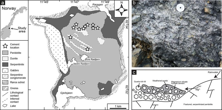
392                                                  L. de Ruiter et al.: Quartz dissolution and M-S-H cement precipitation

semi-quantitative analysis of the cement and other minerals.       times subgrains (Fig. 2a–b), which is typical for dynamic re-
The thin sections were coated with carbon before analysis          crystallization (Passchier and Trouw, 2005). This indicates
with SEM. Rock samples of about 0.5 cm3 coated with gold           that the quartz has been severely plastically deformed and
were studied with the same SEM in secondary electron (SE)          that dislocation glide and recovery resulted in the formation
mode to observe surface textures and morphologies.                 of subgrains. In addition, essentially all quartz grains, includ-
   To observe the structures on the nanoscale, electron-           ing the dynamically recrystallized grains, show undulose ex-
transparent thin foils were obtained by focussed ion beam          tinction, indicating plastic deformation.
(FIB) preparation using a JEOL-JIB 4500 FIB-SEM. The                  A range of recrystallization textures are present, indicating
foils were made from a thin section analysed with SEM at           subgrain rotation and grain boundary migration and larger
a location where quartz was partly dissolved and replaced by       granitic fragments in the cemented rock locally have a my-
cement. The thin section was coated with gold before the FIB       lonitic texture. The newly recrystallized quartz grains and
procedure. The electron-transparent samples were analysed          subgrains vary in size from 1 to 50 µm (Fig. 2c). The sub-
with a JEOL JEM-2100F transmission electron microscope             grains or recrystallized grains within quartz are clearly visi-
(TEM) operating with an acceleration voltage of 200 kV.            ble with TEM as neighbouring grains have a slight change in
Both cement and quartz are known to be beam-sensitive, so          orientation which can be observed when tilting the sample in
careful handling during the TEM sessions was required. The         bright-field mode. In diffraction mode, it can be observed that
exposure and focussing of the beam onto the samples were           the zone axes of two neighbouring grains have a difference
limited as much as possible before images were obtained.           in orientation around 10–15◦ . TEM also reveals the presence
This did not allow for images with a resolution higher than        of many pores and dislocations within the quartz.
those presented in this work.
   Whole rock geochemical analyses were performed by               4.2     Characteristics of weathered quartz
Actlabs Laboratories Ltd. using the lithium metaborate–
tetraborate fusion ICP whole rock ICP/MS package (https:           4.2.1    Microstructures
//www.actlab.com, last access: 1 February 2019). FeO was
determined through titration.                                      Quartz grains embedded within the magnesium silicate hy-
                                                                   drate cement often have irregular grain boundaries, and the
                                                                   cement is present at fractures and pore spaces within the
4     Results                                                      grains (Fig. 3a). Penetration of the cement into the grains
                                                                   divides one grain into multiple smaller grains as it forms
The cemented rocks are composed of felsic rock fragments,          pathways into the grain (Fig. 3a). Comparing cross-polarized
containing mainly quartz, K-feldspar and mica, and ultra-          light (XPL) optical micrographs with BSE micrographs of
mafic rock fragments, containing mainly serpentine and mi-         the same grain shows that the cement pathways coincide with
nor olivine, with cement in between. Aside from the cement,        (sub)grain boundaries of recrystallized grains. At those lo-
quartz is the most abundant phase and is present as single         cations, it can be observed that the outer boundaries of the
grains, polycrystalline quartz aggregates and in rock frag-        recrystallized grains are partly dissolved and that cement is
ments also containing feldspar and mica in addition to quartz.     present. Therefore, the cement pathways typically have a
The quartz grains, which are the potential source of silica for    polygonal shape (Fig. 3a) similar to the initial quartz grain
the magnesium silicate hydrate cement, were studied in de-         boundaries (Fig. 2b). The original polycrystalline quartz
tail, and the results are listed below together with observa-      grains are frequently partly or completely disintegrated into
tions of the non-reacted initial quartz, i.e. the protolith. The   single grains, which provides a network of polygonal quartz
other minerals present in the cemented rocks are not specifi-      grains surrounded by magnesium silicate hydrate cement lay-
cally addressed in this work.                                      ers of around 5–10 µm (Fig. 3b). This can sometimes be
                                                                   observed at the outer boundary of larger quartz fragments,
4.1    Microstructures of initial quartz                           while the inner part is not infiltrated by cement (Fig. 3b).
                                                                   Pore spaces between the cement and quartz are a common
Quartz present in non-cemented rock located away from the          feature within the cemented rock. This creates a honeycomb-
ultramafic rocks, where it is unlikely that high-pH fluid could    like texture within the cement, corresponding to the shape of
have affected the quartz and therefore where no cement was         quartz grains (Fig. 3c). Relics of quartz grains can be found
found, shows the initial appearance of the quartz. The pro-        within these honeycomb-like pore spaces (Figs. 3c and 4c).
tolith can also be observed in large (>1 cm) quartz fragments         The cement forms a coating around the quartz grains
inside the cemented rock, which do not show signs of dis-          (Fig. 4a–b). Figure 4a shows that in the initial stages the
solution in the centres. Many quartz fragments are charac-         layer does not cover the whole surface but is rather present
terized by small (∼ 50 µm) equigranular polygonal neoblasts        as micrometre-sized discs on the surface. However, as shown
with straight grain boundaries together with large (∼ 500 µm)      in Fig. 4b, the cement often coats the complete quartz grains
unrecrystallized grains with undulose extinction and some-         with a layer a few millimetres thick and is also present be-

Solid Earth, 12, 389–404, 2021                                                          https://doi.org/10.5194/se-12-389-2021
L. de Ruiter et al.: Quartz dissolution and M-S-H cement precipitation 393 Figure 2. (a) Optical micrograph with cross-polarized light of recrystallized quartz from Feragen, as indicated by the presence of small equigranular polygonal neoblasts with straight grain boundaries together with large unrecrystallized grains with undulose extinction. This sample has not been weathered or cemented. (b) Zoomed-in view of the polygonal grains. (c) Probability density histogram of the grain size of recrystallized single quartz grains obtained from cemented rocks (n = 1730). Figure 3. BSE images of the relation between quartz (Qtz) and magnesium silicate hydrate (Msh) cement. (a) Cement is present at the grain boundaries within a quartz fragment. Note the hexagonal shape typical for recrystallized quartz. (b) Disintegrated quartz grains with cement between them at the outer boundary (lower right) of a large millimetre-sized grain, while the inner part (upper left) is mainly intact. (c) A quartz fragment that is disintegrated into small grains surrounded by cement on the outer boundary, some of which have dissolved and left behind pore spaces (black) in the shape of the grains. Note that while the left side of the fragment indicates dissolution of disintegrated quartz grains, the right part indicates only disintegration, and the middle and bottom part indicate the original grain. tween two grains as shown in Fig. 4b, which resembles simi- face, resulting in a smooth layer that also fills up etch pits, lar situations as in Fig. 3a–b. In Fig. 4b, the polygonal shape which are common on the surfaces. The cement layer, how- of the quartz grain coated with cement is clearly visible, ever, has a flaky texture at the inside (Fig. 4a), and botryoidal again showing that the cement forms around the recrystal- textures are also commonly present on the outer interface of lized quartz grains. The cement is usually smooth at the in- the cement layer (Fig. 4b). It can be observed that the cement terface since it takes over the topography of the quartz sur- is porous due to the flaky texture. https://doi.org/10.5194/se-12-389-2021 Solid Earth, 12, 389–404, 2021
394                                                    L. de Ruiter et al.: Quartz dissolution and M-S-H cement precipitation

Figure 4. SE images of non-polished whole rock samples showing quartz (Qtz) with a magnesium silicate hydrate (Msh) coating. (a) At
initial stages of cement precipitation, it forms in disc shapes on the quartz surfaces. As the cement forms on the quartz surface, it takes
over the topography of the grains, giving the cement a smooth outer surface but a flaky inner texture. (b) A hexagonal quartz grain almost
completely covered with cement. (c) A quartz grain that started to dissolve after the cement was precipitated, leading to a void between
the quartz and the cement layer. (d) Quartz grains that are completely dissolved; a network of mostly empty pore spaces in the shape of
honeycombs is produced.

   The void between quartz grains and the cement coating as             ent density, even though the complete grains consist of ce-
shown in Fig. 3c is also visible in Fig. 4c, indicating that the        ment (Fig. 5).
quartz grain was reduced in size after the cement formed the
honeycomb-shaped coating around the grain. Empty honey-                 4.2.2   Morphology
combs are also a common feature within the cemented rock
as shown in Figs. 4d and 3c, which sometimes contain rem-               SE images of bulk samples of cemented rock show that etch
nants of quartz grains. This leads to a grid of cement which            pits are abundant on the surfaces of the quartz grains that are
follows the shape of grain boundaries. A void between quartz            surrounded by magnesium silicate hydrate cement (Fig. 6).
and cement can typically only be observed when the cement               Both rectangular (Fig. 6b) and triangular etch pits (Fig. 6d)
layer has a thickness of a least 5 µm, although it should be            occur on different surfaces. The rectangular pits vary in size
noted that much larger areas of cement occur within the rocks           from 0.1 to 4 µm, and smaller pits sometimes occur within
without such large pore spaces. Various stages of the honey-            larger ones. The triangular pits vary from 0.1 to 2 µm. Most
comb texture can be observed within one thin section and                etch pits have steep edges, and the deeper pits often have a
even within one quartz grain. For example, the outer part of            step or spiral structure. The etch pits on one surface always
a quartz grain may consist of empty honeycombs, while in                have the same orientation and are sometimes aligned, as can
the inner part the cement is present at the grain boundaries            be observed in Fig. 6b and d. The density of the etch pits
without a visible void between the quartz grain and the ce-             varies per grain; for example, in Fig. 6b the etch pit density
ment (Fig. 3c). The honeycomb pore spaces can be up to                  is 1010 cm−2 , and there is more reacted surface than non-
50 µm in diameter, corresponding to the size of the recrys-             reacted surface. Etch pits do not occur on every quartz grain;
tallized quartz grains and subgrains. Lastly, honeycomb tex-            for example, the grain in Fig. 4c does not have etch pits even
tures wherein the pore space is filled with magnesium sil-              though dissolution has clearly taken place.
icate hydrate cement are present (Fig. 5). This can be ob-
served since the outlines of the honeycomb texture have a
slightly different contrast in BSE images, indicating a differ-

Solid Earth, 12, 389–404, 2021                                                                https://doi.org/10.5194/se-12-389-2021
L. de Ruiter et al.: Quartz dissolution and M-S-H cement precipitation                                                               395

                                                                         boundaries that do not have any visible amorphous layer, es-
                                                                         pecially further into the quartz.

                                                                         4.3    Composition of till and cemented rock

                                                                         Two samples of till, consisting of sand and collected from
                                                                         a frost boil, were analysed for major elements and com-
                                                                         pared with the composition of a nearby rock that has been
                                                                         cemented with magnesium silicate hydrate (Supplement Ta-
                                                                         ble S1). High SiO2 (87.7 wt % and 89.6 wt % for the till
                                                                         and 72.8 wt % for the cemented rock) and low Al2 O3 (4.5
                                                                         and 4.2 for the till and 4.2 for the cemented rock) charac-
                                                                         terize the samples. The till and the cemented rock contain
                                                                         similar amounts of most oxides (Al2 O3 , TiO2 , FeO, CaO,
                                                                         Na2 O and K2 O). However, the tillite contains a significantly
                                                                         high amount of MgO of 10 wt % compared to 0.8 wt % and
Figure 5. BSE images of honeycomb texture with typical 2–10 µm
diameter pore spaces. The texture consists of magnesium silicate         0.6 wt % in the two samples of till. The loss on ignition (LOI)
hydrate cement (Msh), and the interior is either empty (black) or        value is also significantly higher in the tillite (9.4 wt %) com-
filled with cement (grey) with a different contrast, signifying a dif-   pared to the two till samples (0.7 wt % and 0.5 wt %).
ferent density. The size of the individual honeycomb cells does not
seem to correlate with the cell being filled or not. No quartz (Qtz)
is present, except at the top of the figure.                             5     Discussion

                                                                         5.1    Geochemistry and magnesium silicate hydrate
                                                                                formation
4.2.3   Nanostructures                                                   Till is produced by mechanical weathering and is assumed
                                                                         to represent a robust average composition of the upper conti-
Transmission electron microscopy of a quartz grain that is               nental crust (Goldschmidt, 1933; Gaschnig et al., 2016). The
partly dissolved and surrounded by cement (Fig. 7a–b) shows              composition of the till deposited at the Feragen ultramafic
that an amorphous silica layer of 100–200 nm is present at               body (Supplement Table S1) shows little to no geochemical
the interface (Fig. 7c). The amorphous layer occurs at all the           signature from the underlaying ultramafic body, suggesting
outer boundaries of quartz present in the FIB foil. Different            that the glacier collected bedrock material from an area much
fragments of quartz grains are held together by the magne-               wider than the Feragen ultramafic body. We can therefore not
sium silicate hydrate in the studied sample, but there is often          relate the till to a nearby lithology. The similarity in compo-
a void of 100–200 nm between the amorphous layer and the                 sition between the till and the cemented rock for most oxides
cement (see the bright areas in Fig. 7c). With TEM it can                (besides MgO and SiO2 ) suggests that the till is the protolith
be observed that the magnesium silicate hydrate cement has               of the cemented rock, in accordance with the microstructural
a fibrous texture and that these fibres of the cement are at-            observations. The composition of the cemented rock com-
tached to, and partly intergrown with, the amorphous layer.              pared to the till (reduced SiO2 and increased MgO and LOI)
This makes the interface between the amorphous silica layer              supports the hypothesis that quartz within the till is replaced
and the cement irregular. Quartz and the amorphous silica                by magnesium silicate hydrate cement. The addition of Mg
can easily be distinguished with TEM from the lack of crys-              to the cement formation process can be related to weathering
talline diffraction pattern or contrast compared to the crys-            of the peridotite. At the Feragen ultramafic body, meteoric
talline quartz. EDX indicates that the layer has the same Si-            water has a high pH and is rich in Mg2+ due to the chem-
to-O ratio as the quartz grain, but whether the layer is hy-             ical weathering of ultramafic rock, which is associated with
drated or not is unclear. At internal grain boundaries within            the dissolution of brucite (Mg(OH)2 ). This is clearly visi-
the quartz, there is also often a layer of amorphous material            ble in the weathering rind, which lacks brucite in contrast to
present with a thickness of around 30 nm (Fig. 7d). Based on             the inner part of the rocks (Beinlich and Austrheim, 2012;
the EDX data and diffraction, the layer is also amorphous sil-           Ulven et al., 2017), while olivine and serpentine appear un-
ica and similar in composition to the amorphous layer at the             affected. This also indicates that no Si from the bedrock was
outer interface of the quartz. As shown in Fig. 7d, the thin             added during cement formation and that the Si in the mag-
amorphous layer continues from the thicker amorphous layer               nesium silicate hydrate cement must originate from the till.
at the outer interface and follows the grain boundary inwards            The ultramafic body of Feragen crops out over about 14 km2
for about 1.4 µm. At other grain boundaries, the amorphous               and represents a large reservoir of brucite. The dissolution of
layer can be found further inwards, but there are also grain             brucite in the outer rims of the ultramafic rocks is a fast pro-

https://doi.org/10.5194/se-12-389-2021                                                                 Solid Earth, 12, 389–404, 2021
396 L. de Ruiter et al.: Quartz dissolution and M-S-H cement precipitation
Figure 6. SE images from SEM, showing etch pits on quartz (Qtz) grains that are embedded in magnesium silicate hydrate cement
(Msh). (a) A quartz grain with rectangular etch pits on the surface; the box indicates the location of (b). (b) Rectangular etch pits of
varied sizes; note that all have the same orientation and that some are aligned. The dislocation density is 1010 cm−2 . (c) A quartz grain with
triangular etch pits on the surface; the box indicates the location of (d). (d) Triangular etch pits on a quartz surface that vary in size but have
an identical orientation; note that some of the smaller etch pits are aligned.
cess (Pokrovsky and Schott, 2004; Hövelmann et al., 2012), Magnesium silicate hydrate cement can often be found
and thus the surface water will usually be in, or close to, equi- along the walls of the mine trenches in the chromium mines,
librium with brucite, meaning the pH will be above 10. The where it occurs between the rocks of the mine tailings, indi-
cement forms through the interaction of high-pH, Mg-rich cating that it must have been precipitated after the trenches
meteoric water resulting from dissolution of brucite during were made, which is about 200 years ago. We observed that
chemical weathering of the serpentinized peridotite (Beinlich quartz grains with a diameter of 50 µm within the cemented
and Austrheim, 2012; Ulven et al., 2017). rocks are completely dissolved and (partly) replaced by mag-
nesium silicate hydrate cement at surface conditions in a sub-
arctic climate. Some of these cemented rocks occur in the
5.2 Quartz dissolution and the role of grain boundaries
mine tailings of mines that were in operation about 200 years
ago, indicating that the grains dissolved in less than 200
The microstructural observations within the cemented rock years.
suggest that the outer boundaries of the recrystallized quartz The solubility and dissolution rate of quartz increases
grains are partly dissolved and have been replaced by mag- rapidly with increasing pH, especially above a pH of 10
nesium silicate hydrate cement (Figs. 3a, b and 4a, b). As (Brady and Walther, 1990; House and Orr, 1992). Rim-
cement seems to follow the shape of the grain boundaries, stidt (2015) used multiple experimental studies to deter-
is leads to a honeycomb-structured grid of cement. The fre- mine a rate equation for quartz dissolution. Using this equa-
quently observed voids between quartz and the cement coat- tion, we calculate the assumed dissolution rate of quartz in
ing (Fig. 4c), as well as the empty honeycomb structures the Feragen area. Inserting the highest measured pH and
which sometimes contain relics of quartz (Figs. 3c and 4d), Na+ concentration of 10.6 and 1.3 × 10⁻⁴ mol L−1 (Bein-
suggest that quartz must have been dissolved during or af- lich and Austrheim, 2012), respectively, a temperature of
ter cement precipitation. It also indicates that quartz dissolu- 1 ◦ C (the mean annual temperature – Norwegian Meteoro-
tion is not always accompanied by cement precipitation, al- logical Institute), and assuming a continuous contact with
though completely filled honeycomb structures indicate that the solution, the equation yields a quartz dissolution flux
quartz grains of about 50 µm are completely replaced by ce- of 2.8 × 10⁻¹³ mol m−2 s. However, our microstructural ob-
ment (Fig. 5).
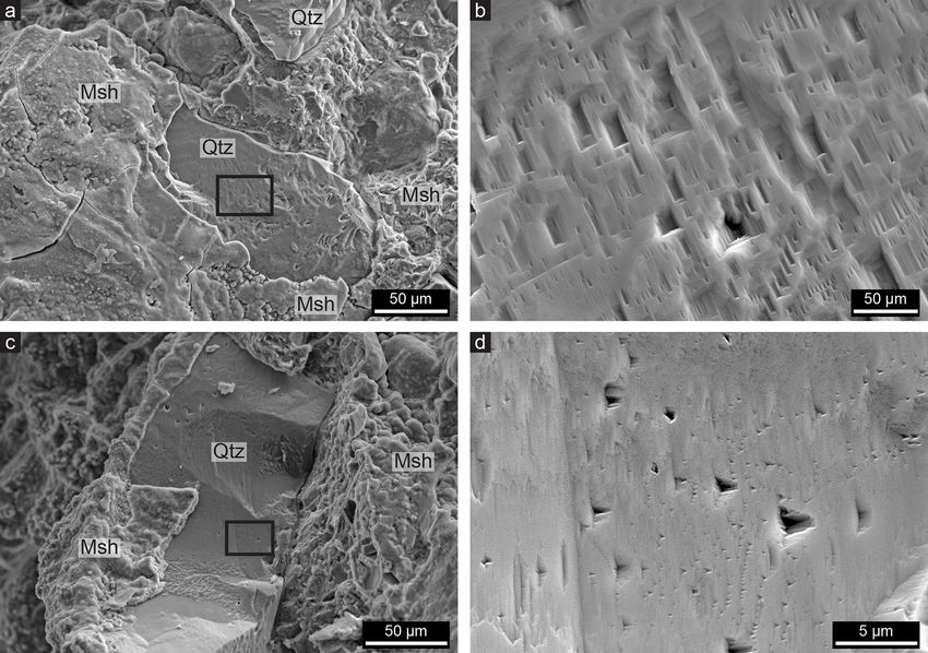
Solid Earth, 12, 389–404, 2021 https://doi.org/10.5194/se-12-389-2021L. de Ruiter et al.: Quartz dissolution and M-S-H cement precipitation 397 Figure 7. (a) SEM image of weathered quartz (Qtz) surrounded by magnesium silicate hydrate (Msh); the rectangle indicates the location of the FIB thin film studied with TEM. (b) Scanning transmission electron microscopy (STEM) image giving an overview of the FIB thin film, showing the locations of (c) and (d) as well as the presence of quartz within the fibrous cement. (c) Bright-field TEM image showing that an amorphous silica (AS) layer of 100–200 nm is present around crystalline quartz that is surrounded by magnesium silicate hydrate cement. Note the presence of fringes indicating crystallinity in the quartz grain and the lack of those in the amorphous silica layer. The fibrous magnesium silicate hydrate is attached to the amorphous silica (e.g. at the red arrow), although pore spaces (the bright areas) are present in between. (d) Bright-field TEM image showing that a layer of amorphous silica of 30 nm is present between two quartz grains; it starts at the thicker amorphous layer on the outer boundary of quartz (lower right) where magnesium silicate hydrate is present, like the layer in (c), and follows the grain boundary for about 1.4 µm inwards, after which it disappears. servations show that a quartz grain with a diameter of 10.6 due to evaporation, which will lower the difference be- 50 µm dissolves in 200 years. This gives a dissolution flux tween the predicted and observed dissolution rate. of 1.75 × 10⁻¹⁰ mol m−2 s (calculated using equations of The cemented rocks found away from the mines could Lasaga, 1984). The dissolution rate observed in the Feragen not have started to form before the end of the Weichselian area is thus 3 orders of magnitude higher than the dissolu- glaciation (11.7 ka). A quartz grain of 50 µm that has com- tion rate predicted by experimental studies. Additionally, our pletely dissolved during this time span would nevertheless predicted rate is calculated using the most favourable values, still indicate a rate faster than predicted by the rate equation: implying that the actual difference between predicted and ob- 3.0 × 10⁻¹² mol m−2 s. This discrepancy is in contrast to the served rates might be even higher. Inserting the average Na+ typically observed difference in dissolution rates of silicate concentration and pH values instead of the highest measured minerals between field data and experimental data; the lat- values, the experimentally established rate equations yield a ter usually suggests higher rates (White and Brantley, 2003; flux of 4.2 × 10⁻¹⁴ mol m−2 s, which is 4 orders of magni- Brantley, 2005). tude lower than the observed dissolution rate. It could be At high-pH conditions, aqueous silica and Mg2+ are speculated that the pH of the solution may increase above known to precipitate together from surface water to form Mg- https://doi.org/10.5194/se-12-389-2021 Solid Earth, 12, 389–404, 2021
398                                                  L. de Ruiter et al.: Quartz dissolution and M-S-H cement precipitation

silicate phases (Tosca and Masterson, 2014). Hence, the ce-        (Yanina et al., 2006). A relationship between the location
ment, a hydrous Mg-silicate, precipitates on the grain bound-      where dislocations intersect the mineral surface and the nu-
aries where quartz has been dissolved and forms a layer that       cleation of etch pits on quartz has been widely reported
surrounds the quartz grains. That the dissolution of quartz        (Blum et al., 1990; Gratz et al., 1991; Yanina et al., 2006).
proceeds faster in our natural case than predicted by experi-      Many of the quartz grains within the cemented rock show
ments might be related to the coupling between the dissolu-        undulose extinction, including the recrystallized grains, in-
tion and the precipitation of a new phase at the surface of the    dicating the presence of dislocations (Fig. 2a). The initial
quartz. The new phase, the cement, forms within the interfa-       non-cemented quartz grains show the same features, indicat-
cial fluid after quartz dissolution and acts as a sink for dis-    ing that crystal plastic deformation occurred before the ce-
solved silica, which subsequently enhances the further disso-      mentation and is not related to the cementation process. The
lution of quartz (Anderson et al., 1998a, b; Schaefer et al.,      deformation could partly be induced by the glaciation due
2018).                                                             to subglacial shearing, which is common for sediments be-
   The dissolution and replacement of polycrystalline quartz       low glaciers (Boulton et al., 2001; Evans et al., 2006). We
grains many times larger than 50 µm can occur within the           speculate that the subglacial shearing acts as a ball mill that
same time span since the dissolution starts at the internal        mechano-chemically activates the quartz and increases its
grain boundaries or subgrain boundaries, which are present         dissolution rate.
due to deformation and recrystallization at an earlier stage          Although increased dislocation density may increase the
(Fig. 2b). This indicates that fluids penetrate polycrystalline    number of etch pits during dissolution, it is not clear whether
grains along the grain boundaries (Jonas et al., 2014). This       this influences the bulk dissolution rate. Multiple studies con-
is likely to be accomplished by intergranular diffusion via        cluded that the influence of dislocations on the total dissolu-
fluid films between the grains (Renard and Ortoleva, 1997;         tion rate of quartz is insignificant (Blum et al., 1990; Gau-
De Meer et al., 2005). The combination of dissolution on the       tier et al, 2001; Lasaga and Luttge 2001). However, experi-
surfaces of the grains and diffusion via intergranular fluids      ments showed a relationship between the pH and the number
has been proposed as the main mechanism for the chemi-             of etch pits, indicating that most etch pits form when the pH,
cal weathering of quartzite and sandstone (Piccini and Mec-        and thus the dissolution rate, was highest (Knauss and Wol-
chia, 2009; Wray and Sauro, 2017). In quartz-rich rock, the        ery, 1988). Brantley et al. (1986) showed that if the silica
intergranular fluids will be rich in H4 SiO4 (silicic acid), the   concentration is far below a critical concentration, etch pits
main form of dissolved silica occurring in nature (Iler, 1979).    grow rapidly, while at a higher concentration dissolution oc-
Since the concentration of silicic acid in the meteoric wa-        curs without etch pits. The high abundance of etch pits on
ter outside the rock or in larger fractures within the rock is     the quartz surface of grains in the cement thus indicates dis-
much lower, the silicic acid will diffuse from the intergran-      solution that is far out of equilibrium and a high dissolution
ular space to the fractures and larger pore spaces where the       rate. The aligned etch pits in Fig. 6b and d might represent
meteoric water is present (Piccini and Mecchia, 2009). This        deformation bands or subgrain boundaries, since these are
favours diffusion of silica away from the intergranular fluids     characterized by the concentration of dislocations.
and enhances the dissolution of quartz at the intergranular
surfaces within the rock.                                          5.4   Amorphous silica layers
   Thus, the microstructure of the quartz protolith is also
likely to contribute to the dissolution rate. Owing to the de-     The amorphous silica layer present between the quartz and
formation and subsequent dynamic recrystallization, the sur-       cement (Fig. 7c) must be related to the dissolution process
face area would be significantly increased, and hence the to-      since it occurs at the outer boundary of quartz grains that
tal amount of dissolved quartz can be much higher than for         are partly dissolved during cementation (Fig. 7a). The for-
non-recrystallized quartz. As shown in Fig. 3a, the cement         mation of an amorphous silica layer as a result of dissolu-
first forms at the grain boundaries, leading to the disintegra-    tion has been reported for other silicate minerals in multi-
tion of recrystallized polycrystalline quartz grains (Fig. 3b)     ple experimental studies (Casey et al., 1993; Hellmann et
multiple millimetres in diameter to single quartz grains be-       al., 2003; Daval et al., 2011; Ruiz-Agudo et al., 2012) and
tween 1 and 50 µm, the size of the recrystallized grains           for natural rock samples (Nugent et al., 1998; Zhu et al.,
(Fig. 2c). These grains are sometimes dissolved completely         2006). The mechanisms that form this layer and the influ-
(Fig. 3c). Fractures and inclusions are also starting points of    ence they have on the dissolution rate of silicate minerals are
cement precipitation.                                              a matter of debate. Most recent experimental studies indicate
                                                                   that the layers form due to an interface-coupled dissolution–
5.3   Etch pits                                                    precipitation process (Hellmann et al., 2012; Ruiz-Agudo et
                                                                   al., 2012, 2016). These studies show that the layer forms be-
Triangular and rectangular etch pits are abundant on quartz        cause the fluid layer at the interface becomes saturated with
within the cement (Fig. 6) and are related to the rhombohe-        silica upon dissolution of the silicate surface, even though
dral and prismatic surfaces of quartz crystals, respectively       the bulk fluid is far undersaturated, so that amorphous sil-

Solid Earth, 12, 389–404, 2021                                                          https://doi.org/10.5194/se-12-389-2021
L. de Ruiter et al.: Quartz dissolution and M-S-H cement precipitation 399
ica subsequently precipitates at the interface. Studies have between the cement and the quartz (Fig. 7c). The porosity of
indicated the co-occurrence of dissolution through etch pit the cement has not yet been quantified.
formation and amorphous material precipitation (Jordan et Amorphous layer precipitation is usually thought of as
al.,1999; Ruiz-Agudo et al., 2012), similar to the observa- slowing down or ceasing dissolution, since it covers the re-
tions of quartz interfaces in this study. However, it has not active surface (Daval et al., 2011). However, the reaction of
been shown before that this mechanism is also involved in amorphous silica to porous magnesium silicate hydrate ex-
quartz dissolution, although the growing amount of literature poses the surface again and could thus lead to more disso-
on such surface altered layers suggests that they widely oc- lution and subsequent amorphous silica precipitation, creat-
cur on various silicate minerals. Moreover, Pope (1995) dis- ing a continuous cycle of dissolution and precipitation (Ruiz-
covered amorphous silica layers on weathered quartz from Agudo et al., 2012). Another possibility is that the amor-
moraine soils and observed these layers at internal grain phous layer dissolves at the outer boundary, while quartz
boundaries and along fractures. Geochemical calculations dissolves and reprecipitates as amorphous silica at the in-
performed with PHREEQC (Parkhurst and Apello, 1999) in- ner boundary due to the presence of a fluid layer between
dicate, however, that if quartz dissolves in a high-pH so- the quartz and the amorphous layer (Hellmann et al., 2012).
lution, the solution will remain undersaturated with respect Both theories would result in the continuous dissolution of
to amorphous silica (Supplement Fig. S1). Quartz dissolu- quartz regardless of the amorphous silica precipitation.
tion by itself thus probably cannot supersaturate the solution The intergranular thinner amorphous layers again indicate
with respect to amorphous silica. External factors that could the infiltration of the reactive fluids and the start of dissolu-
supersaturate the interfacial fluid such as evaporation and tion at the grain boundaries (Fig. 7d). Although the obser-
freeze–thaw cycles must therefore play a role. This is also vations of intergranular amorphous layers are limited since
suggested by the cement being limited to the surface, where they can only be observed with TEM, it is likely that they
evaporation takes place. The supersaturation thus seems to be will develop into cement layers as in Fig. 3a. The possibility
generated by a combination of quartz dissolution and evapo- of infiltration will accelerate the replacement reaction from
ration, resulting in the precipitation of amorphous silica. quartz to cement, and these findings emphasize the impor-
It is well known from experiments that amorphous silica tance of preconditioning the quartz by deformation to pro-
and brucite will react to magnesium silicate hydrate cement vide intergranular fluid pathways.
(Zhang et al., 2012), and the geochemical calculations (Sup-
plement Fig. S1) also show that if quartz or amorphous sil- 5.5 Mass transport and cement precipitation
ica dissolves in a solution that is in equilibrium with brucite,
the solution will be supersaturated with respect to multiple When the cement layer around a quartz grain has reached a
Mg-silicate phases. It is thus likely that in our natural case, thickness of about 5 µm, the quartz is often separated from
the amorphous silica is incorporated into the magnesium sil- the cement by a void. This suggests that the quartz grains
icate hydrate cement under Mg-rich and high-pH conditions. continue to dissolve while the cement precipitation ceases,
Whether the amorphous silica is directly incorporated into which leads to honeycomb textures as can be observed in
the cement or dissolves first is unclear, although experiments Fig. 4c. The formation of the honeycomb texture is remark-
have shown that the formation of Mg-silicates often involves ably similar to the formation of cavities in experimentally
poorly crystallized, or gel-like, precursors or intermediate produced magnesium silicate hydrate cement that is made
phases (Steefel and Van Cappellen, 1990; Baldermann et with silica fume particles, whereby the cement precipitates
al., 2018) that transform into more crystalline phases due to on the surface of these particles, after which the particles dis-
progressive dehydration, which involves the loss of weakly solve and no cement fills the gap (Zhang et al., 2018).
bonded surface water (Tosca and Masterson, 2014). Such de- Ruiz-Agudo et al. (2016) suggested that whether amor-
hydration processes might be the result of evaporation. It is phous silica will precipitate as a result of the dissolution of
unclear why amorphous silica precipitates first and magne- silicate minerals depends on the ratio between reactive sur-
sium silicate hydrate does not precipitate directly. This could face area and mass transport, since the dissolution rate needs
possibly be related to the low nucleation barrier of amor- to be fast compared to the diffusion of dissolved ions to
phous silica making it more favourable to precipitate amor- the bulk solution to create a saturated fluid layer. This sug-
phous silica on the interface rather than magnesium silicate gests that a low flow rate is required for the precipitation
hydrate or the different thermodynamic properties that the of amorphous silica and hence for subsequent precipitation
fluid boundary layer has compared to the bulk fluid. Since the of cement. The lack of cement precipitation inside the hon-
cement is porous and nanocrystalline, diffusion can continue eycombs might therefore be related to a high flow rate and
once a layer has built around the quartz grains (Fig. 4b), mak- diffusion due to larger pore spaces, and it indicates the re-
ing it possible for quartz to continue to dissolve and for the lease and transport of silica instead of the precipitation of
cement layer to become thicker (Fig. 4c–d). This could also amorphous silica. At confined spaces like grain boundaries,
be accommodated by fluid moving through the small void transport of silica away from the dissolving surface is lim-
ited; amorphous silica can precipitate, and thus cement can
https://doi.org/10.5194/se-12-389-2021 Solid Earth, 12, 389–404, 2021400 L. de Ruiter et al.: Quartz dissolution and M-S-H cement precipitation form. However, if quartz is replaced by porous cement the out of equilibrium; (3) the interfacial fluid layer at the quartz permeability increases. This might enhance the flow rate and surface gets saturated due to quartz dissolution and evapo- the transport of silica and magnesium so that the cement no ration, and amorphous silica precipitates; (4) the amorphous longer can precipitate (Fig. 4c). In some cases when several layer reacts with the high-pH, Mg-rich fluids to form mag- neighbouring grains dissolve simultaneously, local supersat- nesium silicate hydrate cement; (5) the fluid can still access uration with respect to the cement phase is maintained, and the quartz surface since the cement is porous and the amor- the cement continues to precipitate as the entire quartz grain phous silica layer has now been removed by the reaction, so dissolves, leading to complete replacement (Fig. 5). the process of quartz dissolution, amorphous silica precip- Disruptions at the quartz–cement interface might also lead itation and subsequent cement precipitation will continue; to enhanced fluid transport. Observations similar to the ce- (6) changes in fluid flow rates and/or fluid chemistry could ment honeycombs have been made for pyroxene and amphi- lead to the ceasing of cement precipitation and therefore the bole that have been weathered to clay minerals (Proust et al., formation of honeycomb textures; (7) diffused silica and dis- 2006; Velbel and Barker, 2008). Velbel and Barker (2008) solved brucite can co-precipitate as cement at some locations described the continuous dissolution of pyroxene after the away from the quartz surfaces, leading to cementation of the outer layer has been transformed to smectite and ascribed rock fragments. Recrystallization before this process has pre- this to mechanical disruption at the smectite–pyroxene inter- conditioned the quartz by providing grain boundaries which face due to hydration episodes that lead to tensional forces. A can act as fluid pathways with confined conditions. These rupture between the smectite and the pyroxene subsequently are the ideal conditions for the replacement process, leading improves the fluid access, and thus mass transport and dis- to the relatively fast replacement of the intergranular grain solution of the pyroxene are favoured. From de Ruiter and boundaries of quartz by cement. Austrheim (2018) it is known that the magnesium silicate Another relevant and widely observed phenomenon asso- hydrate cement phase is related to the clay minerals kerolite ciated with pressure solution that might play a role is the and stevensite, the latter being an Mg-smectite that is known enhancement of quartz dissolution in the presence of mica to shrink and swell with hydration cycles. In addition to the or clay minerals like smectite (Hickman and Evans, 1995; hydration cycles, freeze–thaw cycles could play a role in the Bjørkum, 1996; Schwarz and Stöckhert, 1996; Fisher et al., disruption at the cement–quartz interface. Besides changes 2000). The reason for this phenomenon is still unclear, al- in fluid flow, chemical changes in pore fluids might also play though multiple recent experimental studies suggested that a role in the formation of the honeycomb pore spaces. The electrochemical surface potentials play a key role and are geochemical calculations show that the pH of the solution more important than pressure itself (Meyer et al., 2006; will decrease with the continuation of quartz dissolution (see Greene et al., 2009; Kristiansen et al., 2011); therefore, it the Supplement). This would locally increase the solubility could be a chemical rather than a mechanical process. This of the cement in the cavities between the cement and quartz, would mean that no significant pressures are required and and its precipitation might therefore slow down or cease. that pressure is only needed to keep the surfaces in close The precipitation of cement between different rock frag- proximity, since the diffuse electric double layers, which are ments instead of directly around quartz could be accom- on the nanometre scale, of both surfaces must overlap. As plished by the transported silica, leading to the cementation shown by Kristiansen et al. (2011), an opposing surface with of the rock fragments and grains and hence the formation a more negatively charged surface potential than quartz will of a solid rock. This cement likely precipitates from solu- increase the dissolution rate of quartz; moreover, the surface tion upon evaporation, as is indicated by the fact that cemen- potential of mica decreases rapidly with increasing pH, lead- tation is limited to the surface, which is comparable to the ing to a much lower surface potential for mica than for quartz formation of other Mg-silicate phases (Tosca and Masterson, at a pH around 10. Mica is a representative 2 : 1 phyllosili- 2014). Mg2+ is present in the meteoric fluid due to weather- cate mineral, so it is likely that other phyllosilicate minerals ing of brucite but must be transported through surface water have similar values. The exact amount of pressure needed or groundwater before precipitating as cement, during which or involved in the dissolution is nevertheless unclear, and it part of it is lost in the discharge of water. Hence, it is diffi- therefore remains speculation whether the magnesium silica cult to make a mass balance based on the observations. Fur- hydrate cement, which is a 2 : 1 phyllosilicate (Roosz et al., thermore, other minerals might contribute to the Si and Mg 2015; de Ruiter and Austrheim, 2018), will enhance the dis- concentration in solution. For example, it can occasionally be solution of quartz at ambient conditions by precipitating on observed that feldspar is also replaced by magnesium silicate the quartz surface and having a more negative electrochemi- hydrate cement (de Ruiter and Austrheim, 2018). cal surface potential than quartz. Taking all the observations into account we propose that the dissolution of quartz and the precipitation of cement oc- cur through the following steps: (1) the bulk fluid has a high pH and is rich in Mg2+ due to brucite dissolution; (2) quartz dissolves (through etch pits) due to conditions that are far Solid Earth, 12, 389–404, 2021 https://doi.org/10.5194/se-12-389-2021
L. de Ruiter et al.: Quartz dissolution and M-S-H cement precipitation                                                            401

5.6    Relevance for synthetic magnesium silicate hydrate         cate hydrate cement through interface-coupled dissolution–
       cement                                                     precipitation. The process involves the formation of a
                                                                  nanometre-scaled layer of amorphous silica, which acts as
Natural magnesium silicate hydrate cement is similar, both        a precursor for the magnesium silicate hydrate phase. High-
compositionally and structurally, to synthetic M-S-H cement       pH (∼ 10), Mg-rich fluids resulting from weathering of ul-
(de Ruiter and Austrheim, 2018), and it is therefore reason-      tramafic rocks initiate the replacement process. The rate of
able to ask what we can learn from nature in our attempts         quartz dissolution is about 3 orders of magnitude higher than
to develop M-S-H cement for commercial use. M-S-H ce-             experimentally derived rate equations suggest under the pre-
ment has been suggested as a low-CO2 cement that could            vailing high-pH conditions. This discrepancy is likely caused
replace Portland cement (Imbabi et al., 2012), although it is     by the precipitation of the cement within the interfacial fluids
currently mainly of interest as a cement for the encapsulation    subsequent to quartz dissolution, as this acts as a sink for the
of nuclear waste due to its pH being lower (9–10) than that       dissolved material and therefore enhances dissolution. Pre-
of conventional Portland cement (>12) (Zhang et al., 2011,        conditioning of the quartz by deformation further enhances
2012). This is beneficial for the storage of, for example, Al-    the replacement process as it provides intergranular grain
containing nuclear waste, which causes corrosion problems         boundaries that could act as fluid pathways and therefore as
and the dangerous release of hydrogen gas when encapsu-           starting points for the dissolution of quartz and precipitation
lated in Portland cement (Zhang et al., 2012).                    of cement.
   Human-made M-S-H cement is produced from a reactive
Si source like silica fume, which is amorphous silica consist-
ing of spherical particles about 150 nm in diameter. It is an     Data availability. Data are available upon request.
expensive material even though it is an industrial by-product.
One of the main challenges in the development of M-S-H
cement for large-scale production is the need for a reactive      Sample availability. Samples are available upon request.
silica source that is inexpensive and widely available. The
natural example shows that M-S-H forms from micrometre-
sized quartz grains that are preconditioned by deformation        Supplement. The supplement related to this article is available on-
and recrystallization. Quartz mylonite is abundant in nature,     line at: https://doi.org/10.5194/se-12-389-2021-supplement.
and further testing may show if such quartz can compete
with silica fume. The results of this study might provide the
first steps to use widely available quartz in the production of   Author contributions. LdR carried out the experiments and field-
                                                                  work and prepared the paper with contributions from all co-authors.
M-S-H cement. Furthermore, a porous honeycomb-textured
                                                                  HA contributed to the fieldwork and experiments and supervised
cement, as formed in nature, might be interesting in spe-         the project. AEG carried out the TEM experiments. DKD led the
cific applications since honeycomb structures in general are      funding acquisition.
known as relatively light but strong structures. The high-pH
fluids needed to form natural M-S-H are formed by dissolu-
tion of brucite during weathering of serpentinized peridotite.    Competing interests. The authors declare that they have no conflict
Brucite is typically intergrown with serpentine and difficult     of interest.
to separate, although weathering processes effectively dis-
solve brucite and provide us with the high-pH, Mg-rich fluid.
   Natural cement forms in a century during a fast process on     Acknowledgements. In addition to funding from Horizon 2020,
a geological timescale. However, to make this process rele-       the project was supported by the Research Council of Norway
vant to the cement industry the process must be accelerated.      through the Norwegian Centre for Transmission Electron Mi-
Further research has to focus on this aspect and look for pos-    croscopy, NORTEM (197405/F50). We thank Ole Ivar Ulven for
sible catalysers. More research is furthermore needed to anal-    his assistance in the field and constructive discussions, Berit Løken
yse the long-term durability of this material, although me-       Berg for the help with the scanning electron microscope, Tar-
                                                                  jei Bondevik for his lessons on focussed ion beam sample prepara-
chanical tests on M-S-H cement are promising as they show
                                                                  tion, Joanna Dziadkowiec for the helpful discussions on interfacial
that the compressive strength can exceed conventional Port-       processes, and Andrew Putnis for his useful comments on the pa-
land cement and can be influenced by, for example, the Mg-        per. The reviewers are thanked for their constructive comments that
to-Si ratio (Zhang et al., 2012; Jin and Al-Tabbaa, 2014).        have helped to improve this paper.

6     Conclusions                                                 Financial support. This research has been supported by Horizon
                                                                  2020 (grant NanoHeal (no. 642976)).
Quartz dissolution in the weathering zone of an ultramafic
complex can lead to the precipitation of magnesium sili-

https://doi.org/10.5194/se-12-389-2021                                                            Solid Earth, 12, 389–404, 2021
You can also read