A-PICK Automated Cell and Tissue Acquisition/Deposition System - User Manual - Single cell collection and tissue microdissection ...
←
→
Page content transcription
If your browser does not render page correctly, please read the page content below
A-PI CK
Automated Cell and Tissue
Acquisition/Deposition System
User Manual

                                Get a Hold of Your Cell

                   2021
Contents

 1    Introduction                               1

 2    Safety                                     2

 3    Components and Accessories                 3

 4    Initial Set Up                             4

 5    Using A-picK™                              5

 6    PIKCELLS™ – Main Controls and Operations   7

 7    Basic Operation                            15

 8    Sample Protocols                           29

 9    Troubleshooting                            39

 10   Technical Specifications                   40

 11   System Performance                         41

 12   Warranty and Liability                     42

 13   Contact                                    42
1       Introduction
A-picKTM, an automated capillary-based vacuum pulse assisted cell and tissue acquisition system,
is the key to reliable, precise, cell and tissue sample acquisition prerequisite for a range of in
vitro studies, including cell and region-specific tissue experimentation and single cell analysis.

This vacuum pulse-assisted capillary based system, A-picKTM, is compatible for direct integration
with Olympus IX51/71/81 and IX73/83 inverted microscopes or for use with Olympus IX53,
NIKON Eclipse MA100, and other inverted microscopes (check for compatibility) using the
universal microscope straddle (sold separately).

It allows for automated acquisition and deposition of specific cells from adherent cell cultures
based on their morphology, location or fluorescent label. It can also collect single cells from
suspension cell cultures and individual multicellular spheres from three-dimensional (3D) cell
cultures. A-picKTM collects cells without compromising cell viability, thus enabling primary
culturing or recultivation of the collected cells.

In addition to the collection of individual cells from culture dishes, A-picKTM performs isolation
of single cells and subanatomical regions from various brain tissue samples prepared by
different methods, such as fresh frozen tissue, sucrose treated tissue, and fresh live tissues,
with minimal contamination of surrounding components, while leaving the intracellular
structure and molecules intact.

A-picKTM can work with tissue sections up to 500 µm thickness, suitable for analyses that
require large amounts of sample material, such as proteomics. A-picKTM may also be used for
the collection of micrometric regions of interest from fixed (e.g. PFA-fixed) and archival tissue
specimen, such as formalin fixed paraffin embedded (FFPE) tissue samples.

Samples collected using A-picKTM may be used for a wide range of downstream applications and
techniques used in modern molecular biology, targeting both protein and nucleic acids,
including, but not limited to, quantitative RT-PCR, global gene expression, Next Generation
Sequencing (NGS), epigenetic, and proteomics studies.

                                                1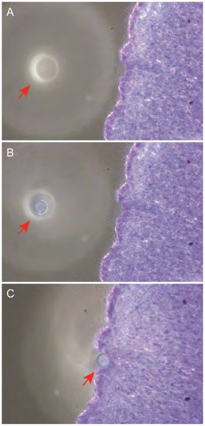
2      Safety
1.   Handle glass capillaries with care. Capillaries have sharp tips and can break on or under
     skin surface upon contact. It is strongly recommended to always wear goggles and
     gloves during handling.
2.   Install A-picKTM over an inverted microscope, level surface and allow at least 5 inches of
     space all around A-picKTM.
3.   Always use the power supply and cord provided with the unit. If a proper power supply
     and cord are not used, product safety performance cannot be warranted.
4.   When installing A-picKTM, route the power cord away from the microscope frame and A-
     picKTM unit.
5.   Always ensure that the grounding terminal of the A-picKTM unit and that of the wall
     outlet are properly connected. If the unit is not grounded, NeuroInDx cannot warrant
     electrical safety.
6.   Never allow any objects to penetrate any openings on the A-picKTM unit as this could
     result in user injury and damage to the instrument.
7.   Do not insert objects into the capillary holder other than filters and disposable capillary
     units (DCUs).
8.   When A-picKTM is not in operation, be sure to turn the power off and disconnect the
     power cord from the connector socket of the A-picKTM unit or from the wall power
     outlet.
9.   Dispose used capillaries (DCUs) into a biohazard glass waste container according to
     regulations.

     Caution: A-picKTM components contain hazardous materials.          A-picKTM consumables
     should be disposed according to local regulations.

                                              2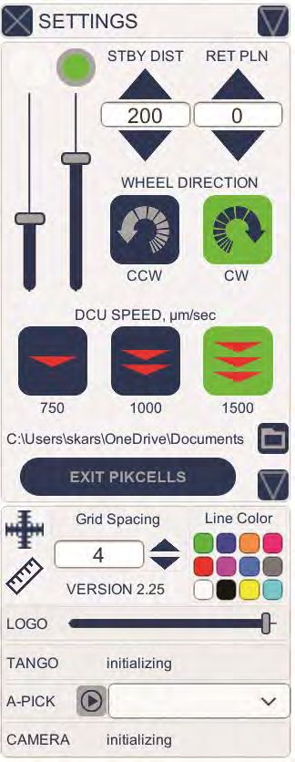
3      Components and Accessories
A-picKTM (Figure 1) consists of Sample Collection Assembly (Head) at top with adjustable LED
ring light, Vacuum Line and Electric Cables, and Control Box with vacuum and pressure module,
and a power supply with cord. A-picKTM may be purchased with a direct adapter or a Universal
Straddle that fits over an inverted microscope with a SCAN IM motorized stage from
Märzhäuser Wetzlar GmbH & Co.KG. Ready-to-use Disposable Capillary Units (DCUs) for cell
collection and tissue dissection and filter attachments are sold separately.

Figure 1: Major components of A-picKTM: (1) A-picKTM Sample Collection Assembly (Head); (2)
Micromanipulators; (3) Vacuum and Pressure Line and Electrical Cables; (4) Motorized stage; (5)
Universal Sample Holder; (6) Olympus IX73 Inverted Microscope; (7) Personal computer with
PIKCELLS™ software for process control; (8) A-picKTM Control Box; (9) Side panel of A-picKTM
Control Box with the green Calibration wheel.

                                              3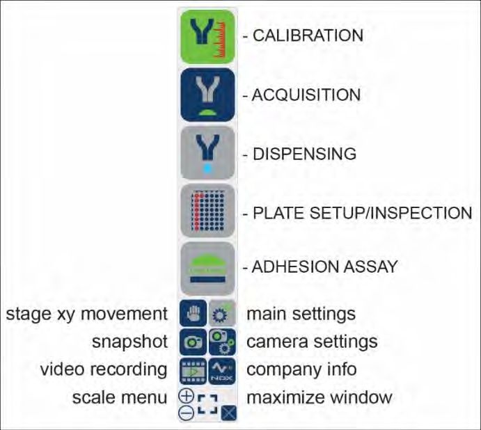
4       Initial Set Up
Make sure that the following items are present for proper operation of A-picKTM:

  1.   A-picKTM unit (Sample Collection Assembly and Control Box) (Fig. 1) - supplied
  2.   Inverted Microscope compatible with A-picK™ (Fig. 1)
  3.   Motorized microscope stage (Märzhäuser Wetzlar GmbH & Co.KG SCAN IM) (Fig. 1)
  4.   0.5X C-mount adapter for camera
  5.   Hex wrenches (2, 2.5, 3, 4, & 5 mm) - supplied
  6.   Power supply and cord (one of each) - supplied
  7.   Personal computer with mouse and keyboard meeting the following requirements.
              a.   Intel i5/Ryzen 3 or better
              b.   8GB RAM or more
              c.   SSD Drive
              d.   USB3

Proper installation of all parts is required for A-picKTM to work properly. Make sure the
following steps are completed before attempting to use the system. Refer to your microscope
manual for operation specific to the microscope.

NOTE: Sample videos and straddle installation instruction video are available on our YouTube
channel: http://www.youtube.com/NDXInc

NOTE: If Universal Straddle is used instead of direct integration with a microscope, please
refer to UnipicK+™ instruction manual at www.ndx-instruments.com/support/downloads.
The same installation sequence is used for A-picK™ instrument utilizing the Universal Straddle
system.

Power supply and cord
Connect the power supply and the cord. Plug the female cord plug into the power jack located
in the rear wall of the A-picKTM control box and plug the power cable into the outlet. Use only
the supplied power supply and cord.

                                                4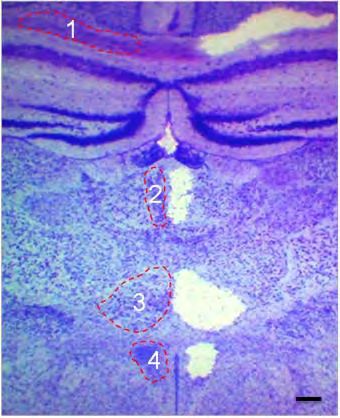
5       Using A-picK™
5.1 Terminology

Starting position:            Highest vertical position for the DCU (i.e. 0); the initial position
                              when the unit is first turned.

Home position:                Calibration of Collecting/Dissecting or Dispensing position of the
                              DCU tip determined by the user. Homing is performed prior to
                              every collection/dissection and dispensing procedure.

Standby position:             1 mm (recommended) above the Home position for Acquisition
                              mode and 10 mm for Dispense mode. DCU will be lifted to
                              Standby position after each single acquisition or dispensing event.
                              DCU returns to Standby position after each sampling until the
                              Home position (Acquisition plane or Dispense plane) or the
                              system has been reset.

5.2 Power

To turn the power on, turn the black switch on the back panel of the Control Box. The green
indicator light on the back will turn on (Figure 1). To turn off the unit, press the switch again.

                                                5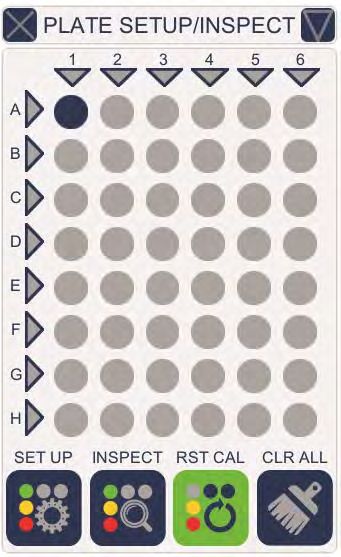
Caution: Do not switch the system on and off quickly. After turning the system off,
          wait at least 10 seconds before switching it back on

5.3 Filter and DCU attachment
Turn the A-picKTM Head 90˚ counterclockwise to expose the male luer connector. Holding the
outer rim of the filter, connect the female luer lock connector of the filter to the male luer
connector on the A-picKTM Head. Do not overtighten the filter, as this will damage its female
luer lock. Next, attach a DCU to the filter.

         Caution: DCU consists of two parts, the hub base with a female luer lock connector
         and a glass capillary component. Always handle a DCU by the hub base to avoid
         injury and damage to the capillary.

Figure 2:     A-picKTM Sample Collection Assembly, a.k.a. Head (1). The following components
are shown: (2) Shield covering the green horizontal calibration light used for DCU tip
identification during calibration procedure; (3) Vacuum line and electrical cable. The Head
should be turned full 90˚ for disposable capillary (DCU) attachment/removal. The x-y position of
the DCU is controlled by the knobs on the linear stages/micromanipulators (4 and 5).

5.4 X-Y control
To center the tip of the DCU in the field of view, use the manual dials (Figure 2) on the linear
stages/micromanipulators at the base of the A-picKTM Head at the mounting site.

                                               6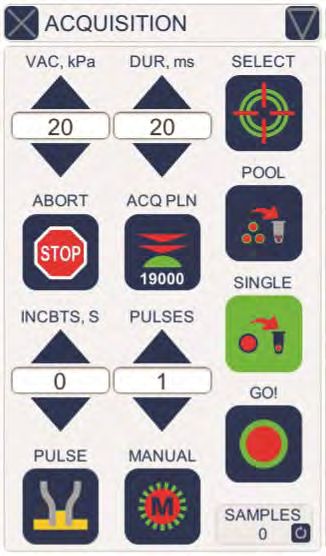
6       PIKCELLS™ - Main Controls and Operation
PIKCELLS™ software operates the instrument via personal computer. It offers controls for
calibration sequences, plate setup, sample collection, sample dispensing, fixed tissue
microdissection, single cell adhesion force measurements, and process inspection and
documentation. The following section describes the main menus, operations, icons and their
function. For further instructions on how to use these controls for a specific application,
advance to “Initial Training Exercises with A-picKTM.”

6.1 MAIN MENU
Main menu is represented by six
icons/options:

CALIBRATION controls for setting
positions for both Acquisition and
Deposition planes. It identified and
autocorrects the DCU tip position
relative to the X-Y stage and
measures the DCU tip internal
diameter, which is later used for
calculating the applied force.

The icon turns green when both
acquisition and deposition planes
are set.

ACQUISITION and DISPENSING
control collection and sample
deposition          parameters,
respectively.

PLATE SETUP/INSPECTION defines deposition sequence and designation of wells. It also
permits for inspection of a collection process after acquisition/deposition sequence is complete.

ADHESION ASSAY offers controls for measuring single cell adhesion or detachment force using
RAMP assay or manual measurements.

SETTINGS window provides general controls of A-picKTM, including light intensity, DCU’s vertical
speed, calibration wheel direction, and Standby and Retract distances.

Remaining MAIN MENU icons in the lower part of the menu offer X-Y stage movement, camera
controls, snapshot and video taking. The user may also regulate the size of the menu icons for
convenience.

                                               7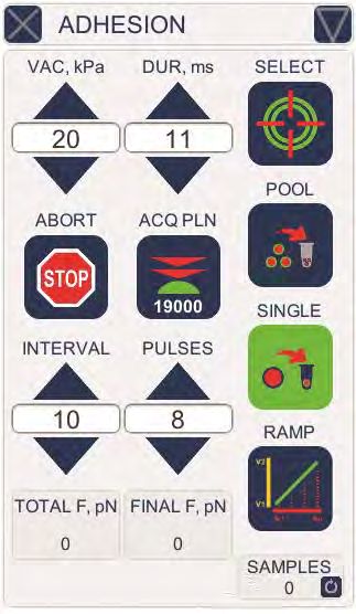
6.2 CALIBRATION
The arrows on the upper right-side (Z-AXIS) control the
DCU’s vertical movement along the z-axis. The mouse icon
at the top right allows for switching the controls of the z-
axis movement to a computer mouse wheel. Single click of
an arrow or a mouse wheel corresponds to a single 1.5 µm
movement. Desired distance may be also typed in the
space between the arrows.
Keep in mind that vertical z-axis movement may be also
performed with the green calibration wheel found on the
right side of the control box. Similarly, a single click of a
slight rotation will move the DCU by 1.5 µm. When the
wheel is turned fast, the DCU will move at a faster rate
(1000 µm/sec).

ACQ, µm is an acquisition plane icon that sets the plane
where sample collection is to take place, i.e. where the
DCU tip meets the sample. It is found by slowly lowering
the DCU with one of the methods described above and
finding a plane where both DCU tip and the sample to be
collected are in the same focus. This may be done using
microscope eye pieces or observing via computer monitor. When the capillary tip comes in
contact with the tissue surface or cells, click on the ACQ, µm icon. When the acquisition plane
is designated, the ACQ, µm icon will turn green. Detailed instructions with initial training will
be provided during installation.

DISP, µm is a dispense plane icon that sets the plane where collected sample(s) will be
deposited. It may be identified in a similar fashion by lowering the DCU to a desired plane (e.g.
surface of the liquid in a sample tube) or preset using one of the ACQ MODE icons found on the
right side of the menu if one of the standard collection scenarios is used. DISP, µm icon will turn
green after dispense plane is identified.

ACQ MODE icons offer one of the four common scenarios: collection from slide to a standard
100 ml PCR tube with 20 µl or 50 µl liquid (left) or collection from 3.5 cm Petri dish to a
standard 100 ml PCR tube with 20 µl or 50 µl liquid (right). Choosing one of the four acquisition
modes will automatically set the dispense plane – DISP, µm icon will turn green and a numerical
value will be shown under the icon.

NOTE: NeuroInDx’s universal sample holder must be in place to use predefined
acquisition/dispensing modes.

RET/SBY icon quickly raises or lowers the DCU to predefined positions preset in the SETTINGS
window (see SETTINGS section).

                                                8
FIND XY icon automatically calibrates the live image distance relative to the movement of the
X-Y stage. This is used for automatically finding and sizing the DCU, and is necessary in order to
use the Auto Tip Positioning function.
AUTO and TUNE icons automatically measure the DCU’s internal and external diameters to
calculate force applied for lifting a target cell, as well as allow for adjustment override by the
user.
6.3 ACQUISITION
The window offers controls for sample collection, including
vacuum strength, impulse duration, target selection,
collection mode and acquisition of regions of interests
from fixed tissues or hard to dissect tissues. It also keeps
track of how many acquisitions were performed since the
most recent calibration.
VAC, kPa and DUR, ms arrows at the top provide controls
for vacuum strength and duration. The vacuum level may
be controlled from 0 to maximum of 70 kPa and the
impulse duration may be set from 1 ms to maximum of
1000 ms. Depending on the sample and the desired result,
various vacuum levels and impulse duration may be used.
We recommend testing these parameters prior to any
collection/dispensing procedure. We recommend starting
with low values and gradually increasing them until the
target sample is successfully lifted.
SELECT icon is used to select desired targets (cells or tissue
regions). Selection is performed via computer screen and a
mouse by clicking on a desired target. Multiple targets maybe selected for a single run.
Two icons below SELECT icon (POOL and SINGLE) are used to designate a specific collection-
deposition mode. When the POOL icon is activated multiple targets are selected and dispensed
into a single tube.
Selecting the SINGLE icon activates the mode of collection in which each selected target is
collected and deposited into a separate tube. This mode is used for single cell collection.
There are two icons in the middle of the ACQUISITION window. ABORT icon stops and cancels
the entire process. ACQ PLN icon indicates the current acquisition plane and may be used for its
slight adjustment (recalibration) by bringing DCU to the current acquisition plane (e.g. 19000
µm) and then using the CALIBRATION window controls to adjust the vertical position of the
DCU tip.
9After the targets are selected, clicking on the GO! icon at the lower right corner will initiate
sample collection and deposition by bringing the DCU down to the acquisition plane and
activating the vacuum and to the dispense plane and activating a pressure impulse at the
selected strength and duration.
The two lower icons (PULSE and MANUAL) and arrows above them provide automatic and
manual pulse modes for acquisition of regions of interest (ROIs) from fixed tissues such as
formalin fixed paraffin embedded or PFA fixed tissue specimen. Pulse is an application of
vacuum impulse with predefined duration and strength without lifting of the DCU tip from the
tissue surface, which allows mixing the digestion liquid inside the capillary barrel.
PULSE icon provides a mode when DCU is in touch with a tissue surface and remains in touch
for the incubation time (in seconds) specified using the arrows above. PULSE icon turns green
when activated. For automatic process, incubation time (INCBTS, S) and specific number of
pulses (PULSES) during incubation period could be preset prior to initiation of a digestion
procedure. At the end of digestion, a standard acquisition sequence is automatically initiated
using predefined vacuum strength and impulse duration.
6.4 DISPENSING
The window offers controls for sample deposition including
desired washing sequence. Like ACQUISITION window, it
keeps track of the number of dispensing events that were
performed (lower right corner).
PRESS, kPa and DUR, ms at the top offer settings for
pressure strength and impulse duration, respectively.
ABORT icon stops the entire deposition sequence.
DISP PLN icon brings the DCU tip to the plane where
sample dispensing is set. This icon may be used for quick
adjustment of the dispense plane during the
collection/deposition sequence.
DISPENSE icon activates a single sample dispensing
sequence.
Three lower arrow settings provide controls for sample
rinsing to ensure all collected material leaves the capillary.
These controls are not required but may be useful when extra small amounts of material are
collected and dispensed.
NOTE: We recommend using low pressure for dispensing starting from 2 kPa and longer
duration time starting from 100 to 200 msec. Excessive pressure will result in a rapid sample
10dispensing, spurting the DCU contents. If not sufficient, pressure and time duration may be
adjusted for optimal sample deposition.
WASH icon at the bottom left of the DISPENSE window activates capillary rinsing that permits
multiple rounds of collection and dispensing within the same capillary to ensure that DCU
contents do not remain in the barrel. The number of such washing cycles and settings (vacuum
and pulse duration) are defined by tapping the arrows for the settings above the blue WASH
icon. WASHES value indicates the total number of cycles. VAC, kPa and DUR, ms preset
vacuum strength and pulse duration, respectively. For example, the window on the side shows
that six rinsing cycles of vacuum strength of 9kPa and duration of 3ms will be performed.
The progress of sample deposition will be shown in the PLATE SETUP window (see below) that
may be accessed at any time by tapping the PLATE SETUP icon in the main side menu. Wells
where collected samples are deposited will be indicated in green.
6.5 ADHESION
This window allows for the comparative estimation of
single cell adhesion or detachment strength, e.g. how much
force is required to lift a cell from the surface. Two output
measurements are provided for the comparative analysis
total force, “TOTAL F, pN”, and final force “FINAL F, pN”.
Both values are based on the algorithm of the RAMP
function. TOTAL FORCE is defined as the sum of all forces
corresponding to the total number of executed pulses.
FINAL FORCE represents the force used for the last and the
highest vacuum pulse in the ramp process. APPLIED PULSES
is the total number of pulses executed.
RAMP function represents a specific number (PULSES) of
vacuum impulses starting with a predefined initial vacuum
strength (VAC, kPa) raised by a predefined interval
(INTERVAL) for each subsequent pulse.
Just like in ACQUISITION window, VAC, kPa and DUR, ms
arrows at the top left provide controls for vacuum strength
and duration used for the initial first pulse.
SELECT icon is used to select desired targets (cells or tissue regions). Selection is performed via
computer screen and a mouse by pointing and clicking on a desired target. Multiple targets
maybe selected for a single run.
11The two icons below SELECT icon (POOL and SINGLE) are used to designate a specific collection-
deposition mode. POOL icon is activated when multiple targets are selected and dispensed into
a single tube.
Selecting the SINGLE icon activates the mode of collection in which each target is collected and
deposited into a separate tube. This mode is used for single cell collection.
ABORT icon will interrupt the RAMP process at any time. Current values for TOTAL FORCE and
FINAL FORCE will be given.
ACQ PLN icon indicates the current acquisition plane and may be used for its slight adjustment
(recalibration) by bringing DCU to the current acquisition plane (e.g. 19000 µm) and then using
the CALIBRATION window controls to adjust vertical position of the DCU tip.
6.6 PLATE SETUP/INSPECTION
The window represents 48 well universal sample holder
used for sample collection and deposition with A-picKTM
automated system. Individual 0.1- and 0.2-ml PCR tubes,
strips or 48-well plates are compatible with the holder.
Samples may be collected from standard microscope
glass slides or cell culture plates.
To set up a plate, move the motorized stage to position
the center of the farthest back left well on the sample
holder to align with your DCU tip position on the x-y
plane. The top left corner well position on the window
will be blinking. Tap the blinking top corner well position.
The circle will stop blinking and turns grey when the stage
position is calibrated, and the SET UP icon will turn green.
The collected samples will now be deposited from top left
well to the bottom right well top to bottom per column,
and from left column to right. Entire columns and rows
may be selected by left-clicking on the corresponding
triangle. A specific well may be prioritized by right-clicking
on it once (prioritized first well will turn bright blue) or deselected by left-clicking (well will turn
grey).
NOTE: When selecting individual wells, the samples will be deposited in the order in which
the wells were selected.
12INSPECT icon opens an additional window where before and after images for each collection.
Wells with deposited samples appear red. Clicking on a red well will display the before and
after image of the sample associated with it.
RST CAL icon clears the plate setup settings, allowing for re-calibration and CLR ALL icon clears
all well selections along with all preselected targets associated with the wells.
6.7 SETTINGS
Left half of the screen allows for the selection (from left to
right) of main light and calibration light intensities.
STBY DIST arrows permit setting desired stand by distance
or distance of the DCU tip from the acquisition plane. The
default distance for standby position during acquisition is 1
mm from the acquisition plane; however, this can be
changed to a shorter distance on this page.
RET PLN arrows set the Retract plane (default setting is 0,
i.e., the highest position). By lowering the vertical Retract
position of the DCU, it may be quickly lowered or raised.
Reducing this distance can minimize the time spent during
calibration procedure or movement of DCU between
different planes (e.g. between slide and test tubes).
Two WHEEL DIRECTION icons below offer a choice of
direction of the calibration wheel to move DCU down:
counterclockwise (CCW) or clockwise (CW - default).
The three DCU SPEED icons permit selection of DCU vertical
movement speed when using the Z-AXIS arrows in
CALIBRATION. The calibration wheel has a set speed of
1000 µm/sec when turned quickly.
Location for the stored image, video, and log files created
during the collection process is shown below. Tap the
Folder icon to change destination.
EXIT PIKCELLS icon exits the program and the downward
arrow at the bottom right opens another window where additional controls are located.
The downward arrow opens a dropdown menu for other controls, namely adding a crosshair to
the view, measuring tool (Ruler icon), LOGO light control, and selection of camera.
136.7 CAMERA
A CAMERA window with standard image controls may be called out from the main menu to
adjust image quality.
The camera controls directly access the camera that is connected to the control box.
147 Basic Operations
7.1 Initial Training Exercises with A-picK™
For sample videos visit our website: www.ndx-instruments.com or YouTube channel:
http://www.youtube.com/NDXInc
1. Start A-picKTM using the power switch on the back panel of the Control box (green logo
in the front will light up).
2. Initiate PIKCELLS™ on your personal computer. Make sure that the correct camera is
connected in order to run A-picK™. Under SETTINGS, tap on the downward arrow at the
bottom right, and check that the system is connected to the correct camera. If not, tap on the X
next to the camera listed and then choose the correct camera from the drop-down list, then tap
on the play icon on the left. Here you can also turn on the grid for the screen. When finished,
tap the downward arrow again to minimize the sub-window.
Caution: Wear gloves and protective eyewear when handling DCUs containing glass
capillaries.
3. Place a marking on a histological glass slide and place it on the motorized stage with 2
drops of distilled water.
4. To attach the filter and DCU; rotate the Head 90˚clockwise and attach a filter directly to
the male luer connecter on the A-picKTM Head. Carefully handle new DCU by its hub base
and attach it directly onto the filter.
NOTE: Green light on the Head is used to visualize the green annulus of the DCU under the
microscope. When attaching a filter and DCU, this light may be turned off. It must be turned
on again before lowering the DCU for calibration. The intensity may be adjusted using the
sliding bar in the SETTINGS window.
5. Rotate A-picKTM Head clockwise so that the DCU tip points down. Make sure that the
head is turned all the way until it reaches a hard stop.
6. Before a run, the system requires calibration. Click on the RET/SBY icon to bring the
DCU tip down by 15 mm. Using the green calibration wheel or Z-AXIS controls in the
CALIBRATION window, carefully bring the DCU down another 2.0 to 3.0 mm. DCU
position will be shown between Z-AXIS arrows, as well as at the bottom of the A-picK
window.
15NOTE: Single calibration wheel movements (one increment) or one click of a mouse wheel
will move the capillary 1.5 µm per step. Moving the calibration wheel fast will increase the
speed to 1000 µm/sec.
7. Switch to 4X objective and slowly moving it up locate the green DCU tip. When in focus,
the annulus of the capillary tip appears as a bright green ring.
8. Use the linear stages/micromanipulators (Figure 2) to center the green annulus ring. It is
recommended to locate the green annulus under the lowest magnification first.
9. Locate the marking on slide using low magnification objective and coarse and fine focus
adjustment knobs to focus on marking.
10. Carefully bring the DCU down until the annulus of the capillary tip comes into focus as a
bright green ring.
11. Stop lowering the DCU when the capillary tip moves with the glass slide when using the
motorized stage. Make sure to move the slide/plate at the slowest speed using the
joystick for the motorized stage or the hand icon to determine if the DCU tip has made
contact with the slide/plate surface. When the DCU tip is in contact with the surface, a
slight motion of the motorized stage will result in a movement of the capillary tip.
12. Click on the RET/SBY icon to bring the DCU to its highest Starting position and repeat
the process from step 6.
7.2 DCU Calibration for Tissue Microdissection
Each newly attached DCU must be calibrated before sampling. For instructional video visit our
website: www.ndx-instruments.com or our YouTube channel:
http://www.youtube.com/NDXInc
NOTE: Depending on the region of interest, DCUs of different internal diameters (IDs) should
be used. The size of desired cells and cell clusters shall determine the appropriate diameters
of the DCUs. An average mouse interneuron is about 15-25µm. For microdissection of brain
anatomical regions (e.g. mouse hippocampus) ~50µm ID DCU is recommended.
Subanatomical regions, such as dentate gyrus or cortical layers, may be collected with ~30µm
ID DCUs. If fine microdissection is required, DCUs with1. Start A-picKTM using the power switch on the back panel of the Control box (green logo
in the front will light up). Initiate PIKCELLS™. Place a tissue slide on the motorized stage
and add buffer to the tissue.
2. Position the slide to a clear spot on the slide adjacent to the tissue sample for
calibration.
3. Rotate the A-picKTM Head 90˚ counterclockwise (Figure 2) to attach a filter directly to the
male luer connecter on the A-picKTM Head. Then carefully handle a new DCU by its hub
base and attach it directly onto the filter.
NOTE: Green light on the Head is used to visualize the green annulus of the DCU under the
microscope. When attaching a filter and DCU, this light may be turned off. It must be turned
on again before lowering the DCU for calibration. The intensity may be adjusted using the
sliding bar in the SETTINGS window.
Caution: DCUs have sharp tips! Handle with care. Improper handling may cause
injuries. Never contact the capillary tip to avoid injury and contamination.
Caution: Always use a filter with the DCU to prevent biological material and liquids
from entering A-picKTM Head. When A-picKTM is not in use, attach a new filter unit to
prevent foreign objects from entering the system until next use.
4. Rotate A-picKTM Head clockwise so that the DCU tip points down.
5. Using the green calibration wheel or Z-AXIS controls in the CALIBRATION window,
carefully bring the DCU down until the capillary tip touches the surface of the liquid.
Optional: Click on the RET/SBY icon to bring the DCU tip down by 15 mm first before
using the calibration wheel or Z-AXIS controls in the CALIBRATION window.
NOTE: Single calibration wheel movements (one increment) or one click of a computer mouse
wheel will move the capillary 1.5 µm per step. Moving the calibration wheel fast will increase
the speed to 1000 µm/sec.
6. Use the linear stages/micromanipulators to locate the DCU halo and position the halo
adjacent to the tissue (Figure 3A). It is recommended to locate the green annulus under
the lowest magnification.
17Figure 3: Three step procedure for DCU calibration. A: Initial
finding of DCU tip (halo, shown with red arrow) in the field of
vision; B: Lowering the DCU until the DCU tip and tissue section
are both in focus; C: Moving the motorized stage to test if the
DCU tip is in contact with the tissue section surface.
7. Use coarse and fine focusing knobs to focus on the
tissue. Slowly bring the DCU down until the annulus of the
capillary tip comes into focus as a bright green ring (Figure 3B).
Lower the DCU until the capillary tip comes in contact with the
tissue (Figure 3C). It is helpful to slowly move the microscope
slide with the motorized stage to determine if the DCU tip has
made contact. When the DCU tip is in contact with the slide
surface, a slight motion of the motorized stage will result in the
simultaneous movement of the capillary tip. If the tug of the
slide movement is observed, move DCU tip slightly up (~ few
micrometers; one click of the green calibration wheel
corresponds to 1.5 µm) until the motion of the motorized stage
no longer pulls the capillary tip. This assures that the lowest
position of the capillary tip will not break the tip upon
downward movement during microdissection.
8. Using the linear stages/micromanipulators to align the annulus of the capillary tip to the
center of the ocular crosshairs.
Caution: Bringing down the DCU too low will cause the capillary tip to break against
the sample slide or plate. If you suspect that a tip has been broken, be sure to check
the surrounding area for broken glass before replacing the DCU to avoid injury.
9. Click on the ACQ, µm icon in the CALIBRATION window to set the calibrated acquisition
plane/Home position. Use the Z-AXIS controls in the CALIBRATION window to lift the
DCU slightly above the acquisition plane when moving the slide.
10. To re-calibrate, go to ACQUISITION window, and click on the ACQ PLN icon. This will
bring the DCU down to the calibrated acquisition plane. Adjust the position of the DCU
with the green calibration wheel or the Z-AXIS controls in the CALIBRATION window.
Once the correct position is set, click on the ACQ, µm icon in the CALIBRATION window.
This will set the new acquisition plane.
11. You may re-calibrate at any time during the acquisition procedure to designate a new
acquisition plane/Home position.
12. Proceed to Cell and Tissue Collection Section.
187.3 DCU Calibration for Adherent Cell Cultures
NOTE: Each new DCU must be calibrated before sampling. For instructional video visit our
website: www.ndx-instruments.com or YouTube channel:
http://www.youtube.com/user/NDXInc
Caution: Wear gloves and protective eyewear when handling DCUs containing glass
capillaries.
TIP: When working with attached cells it is recommended to wash the cells with fresh medium
to remove floating cells. Do not add new medium in excess, as the cells must be just barely
covered.
1. Start A-picKTM using the power switch on the back panel of the Control box once (green
logo in the front will light up).
2. Place a cell plate/dish on the motorized stage.
3. Rotate the A-picKTM Head 90˚ counterclockwise (Figure 2) to attach a filter and DCU.
Attach a filter directly to the male luer connecter on the A-picKTM Head. Then carefully
handle a new DCU by its hub base and attach it directly onto the filter.
Caution: DCUs have sharp tips! Handle with care. Improper handling may cause
injuries. Never contact the capillary tip to avoid injury and contamination.
Caution: Always use a filter with the DCU. The filter will prevent biological material
and liquids from entering A-picKTM Head. When A-picKTM is not in use, attach a new
filter unit to prevent foreign objects from entering until next use.
4. Rotate A-picKTM Head clockwise so that the DCU tip points down.
5. Using the green calibration wheel or Z-AXIS controls in the CALIBRATION window,
carefully bring the DCU down until the capillary tip touches the surface of the liquid.
Optional: If the system has not been calibrated yet, click on the RET/SBY icon to bring
the DCU tip down by 15 mm before using the calibration wheel or Z-AXIS controls in the
CALIBRATION window.
19NOTE: Single calibration wheel movement (one increment) will move the DCU 1.5 µm per
step. Moving the calibration wheel fast will increase the to 1000 µm/sec. Single click on the
PLUS or the MINUS Z-AXIS controls will move the DCU 1.5 µm down or up, respectively.
6. Use the linear stages/micromanipulators (Figure 2) to locate the DCU halo.
7. Use coarse and fine focusing knobs to focus on the cells. Slowly bring the DCU down
until the annulus of the capillary tip comes into focus as a green ring. Position the green
ring over a clear spot. Continue to lower the DCU until the tip has contacted a cell. It is
helpful to slowly move the plate/dish with the motorized stage in order to determine if
the DCU tip has made contact with a cell or the plate/dish surface. If the DCU tip is just
above the slide surface, the edge of the cell will press against the capillary tip (e.g.
Figure 3).
8. When the DCU tip is in contact with the culture plate surface, a slight motion of the
motorized stage will result in the simultaneous movement of the capillary tip. If the tug
of the culture plate movement is observed, move DCU slightly up until the motion of the
motorized stage no longer pulls the capillary tip. This assures that the lowest position of
the capillary tip will not break the tip upon downward movement during dissection.
9. Using the linear stages/micromanipulators align the annulus to the center of the ocular
crosshairs (Figure 2).
Caution: Bringing down the DCU too low will cause the capillary tip to break against
the sample slide or plate. If you suspect that the tip has been broken, be sure to
check the surrounding area for broken glass before replacing the DCU to avoid injury.
10. Click on the ACQ, µm icon to set the calibrated acquisition plane/ Home position. Lift
the DCU before moving to different locations on the slide/plate.
11. To re-calibrate, go to ACQUISITION window and click on the ACQ PLN icon. This will
bring the DCU down to the calibrated acquisition plane. Adjust the position of the DCU
with the green calibration wheel or the Z-AXIS controls in the CALIBRATION window.
Once the correct position is set, tap on the ACQ, µm icon in the CALIBRATION window.
This will set the new acquisition plane. Use the RET/SBY icon to lift the DCU to the n the
ACQUISITION window tap the ACQ PLN icon to bring the DCU back to the Home position.
Re-position the capillary tip using the Z-AXIS controls in the CALIBRATION window or by
rotating the calibration wheel and then push the calibration wheel again to set the new
Home position.
12. You may re-calibrate at any time during the sampling procedure to designate a new
acquisition plane.
2013. Click on the RET/SBY icon and make sure that DCU is lifted high enough to clear the tops
of tubes or any other objects on the motorized stage. Move the X-Y stage to the position
where the sample needs to be dispensed.
14. Calibrate the DCU to identify dispense plane and set the Home position for the
dispensing using the same sequence as described for the selection of acquisition plane.
15. Proceed to Cell and Tissue Collection Section
Caution: When the A-picKTM Head is rotated 90˚ counterclockwise, the DCU will not
return to its initial Starting position. To return the DCU to the initial position with the
RET/SBY icon. To avoid breaking the DCU tip we recommend returning a DCU to its
initial Starting position before removing it from the unit.
7.4 Cell and Tissue Collection
Manual Mode
1. Place sample on the holder and then attach a DCU.
2. Open the software and allow it to initialize. The motorized stage will move to the back-
left corner then to the front-right.
3. Tap on the SETTINGS icon and adjust the ring light and the green LED brightness.
4. Tap on the downward arrow at the bottom right, and check that the system is
connected to the correct camera. If not, tap on the X next to the camera listed and then
choose the correct camera from the drop-down list, then tap on the play icon on the left.
Here you can also turn on the grid for the screen. When finished, tap the downward
arrow again to minimize the sub-window.
5. Open the CALIBRATION window (top icon).
6. Move the stage to an area around where collection will take place and bring the sample
in to focus.
7. Tap the RET/SBY to bring the DCU down by 15mm.
8. Using the linear stages at the base of the head unit, try to align the tip with the center of
the objective.
9. Bring the DCU down to the plane of the samples to be collected. Use the up and down
arrows (for faster movement – speed set under SETTINGS), Plus and Minus icons (for
single step of 1.5 um), or the wheel on the side of the control box (fast rotation for 1000
µm/s and slow movement for single step). Note that the wheel direction can be changed
in SETTINGS.
10. Once the DCU tip is in focus with the ROI, tap the ACQ icon to set the acquisition plane.
If the DCU tip is off center on the screen, lift the DCU several steps up using the Minus
icon, and use the linear stages at the base of the head to adjust its x-y position.
2111. Preset dispense plane can be set by tapping one of the ACQ MODE icons. It is good
practice to try and place the DCU tip in the center of the FOV/screen view. Using the
grid is recommended.
12. ACQ and DISP planes may also be typed in manually, followed by Enter. The icons turn
green when the planes are set.
13. Open the ACQUISITION and DISPENSE windows by tapping their icons (2nd and 3rd icons).
Adjust the settings recommended for the application. At this time, also adjust STBY DIST
under SETTINGS. This will set the distance the DCU lifts after each acquisition.
14. Move the stage to align the ROI with the DCU and tap GO! The DCU will come down and
the vacuum will be applied, then it will lift to the designated standby position set under
SETTINGS.
15. If pooling, move to the next ROI and repeat the previous step.
16. For dispensing, set the values desired under DISPENSE. Lift the DCU using RET/SBY icon
or with the Z-AXIS up arrow and then move the stage so that the desired dispense
location is in the center of view aligned with the DCU’s x-y position.
17. Tap the DISPENSE icon. The DCU will come down to the designated dispense plane and
pressure will be applied. After dispensing, the DCU lifts up to the Retract position
designated under SETTINGS.
Manual Select Mode
1. Place sample on the holder and then attach a DCU.
2. Open the software and allow it to initialize. The motorized stage will move to the back-
left corner then to the front-right.
3. Tap on the Settings icon and adjust the ring light and the green LED brightness.
4. Tap on the downward arrow at the bottom right, and check that the system is
connected to the correct camera. If not, tap on the X next to the camera and choose
the correct camera from the drop-down list, then tap on the play icon on the left. Here
you can also turn on the grid for the screen. When finished, tap the downward arrow
again to minimize the sub-window.
5. Open the CALIBRATION window (top icon).
6. Move the stage to an area around where collection will take place and bring the sample
in to focus.
7. Tap the RET/SBY to bring the DCU down by 15mm.
8. Using the linear stages at the base of the head unit, try to align the tip with the center of
the objective.
9. Bring the DCU down to the plane of the samples to be collected. Use the up and down
arrows (for faster movement – speed set under SETTINGS), Plus and Minus icons (for
22single step of 1.5 um), or the wheel on the side of the control box (fast rotation for
1000um/s and slow movement for single step). Note that the wheel direction can be
changed in SETTINGS.
10. Once the DCU tip is in focus with the ROI, tap the ACQ icon to set the acquisition plane.
If the DCU tip is off center on the screen, lift the DCU several steps up using the Minus
icon, and use the linear stages at the base of the head to adjust its x-y position.
11. Preset dispense plane can be set by tapping one of the ACQ MODE icons. It is good
practice to try and place the DCU tip in the center of the FOV/screen view. Using the
grid is recommended.
12. ACQ and DISP planes may also be typed in manually, followed by Enter. The icons turn
green when the planes are set.
13. If the plate holder will be used with plates or tubes, calibrate the well position by
tapping on the PLATE SETUP icon (4th down from the top). Well A1 will be blinking.
14. Lift the DCU to the starting position (0) or high enough to clear the plate holder and
anything that is mounted on the holder.
15. Move the stage so that the back-left most well is aligned with the center of the screen
where the DCU is positioned. Tap on the blinking well. The SET UP icon at the bottom
of the window will turn green. At a later time, this position can be recalibrated by
tapping on the RST CAL (reset calibration), and then repeating the process.
16. Open the ACQUISITION and DISPENSE windows by tapping their icons (2nd and 3rd icons).
Adjust the settings recommended for the application. At this time, also adjust STBY DIST
under SETTINGS. This will set the distance the DCU lifts after each acquisition.
17. Move the stage so that there is a well contrasted view in the camera. In the
CALIBRATION window, tap FIND XY (it will turn grey when activated) to calibrate the x-y
plane.
18. If Auto Tip Positioning is desired, check the Auto Tip Pos box next to the FIND XY icon.
The AUTO and TUNE icons will turn grey, and the DCU will come down to the acquisition
plane.
19. The system will find the DCU tip automatically and provide its ID and OD. If adjustment
is necessary, use the tuner that appears on the screen to make a better fit. After tuning,
close the tuner by tapping on the X. This value will be used to calculate force. If the
system is having a difficult time finding the tip, try increasing the green LED light
intensity and lower the ring light intensity. If the Auto Tip Positioning is not checked,
the system will assume that the DCU is in the center of the view and there will be no
new measurement of the ID or the OD. It will assume the previously saved values for
calculating force.
20. In the DISPENSE window, tap MANUAL (it will turn green when activated) to activate the
manual selection mode.
2321. In the ACQUISITION window tap SELECT (it will turn green when activated) to activate
the select mode. A small bull’s eye will allow selecting ROIs on the screen.
22. Make the selection(s) by clicking the ROI(s) with the bull’s eye icon, then tap GO!. The
system will automatically go to the ROI(s) and collect sample(s), then rest at standby.
You can continue to select more ROI to continue collecting.
23. In the PLATE SETUP/INSPECT window, tap on INSPECT (it will turn green when activated).
24. Another window WELL INSPECT will appear to the right, providing images of before and
after acquisition from the selected ROIs. The arrow at the bottom right allows the user
to scroll multiple ROIs. The bottom left Go To icon (4 arrows) will move the stage to
center that ROI in the field of view. The green circle to its right can be tapped to turn
red if the user wishes to re-collect to that position. By tapping GO! again, the system
will collect from that position again.
25. For dispensing, set the values desired under DISPENSE. Lift the DCU using RET/SBY icon
or with the Z-AXIS up arrow and then move the stage so that the desired dispense
location is in the center of view aligned with the DCU’s x-y position. Tap the DISPENSE
icon to dispense.
26. If the destination is one of the wells on the sample holder, left click with the mouse on
the well in the PLATE SETUP/INSPECT window. The stage will automatically center the
well in your view. Note: Make sure that the SET UP icon at the bottom left of the
window is not selected (should be in dark blue). If the icon is in green, tap it once to
deselect.
27. Tap the DISPENSE icon. The DCU will come down to the designated dispense plane and
pressure will be applied. After dispensing, the DCU lifts up to the Retract position
designated under SETTINGS.
Auto Dispense Mode
1. Place sample on the holder and then attach a DCU.
2. Open the software and allow it to initialize. The motorized stage will move to the back-
left corner then to the front-right.
3. Tap on the SETTINGS icon and adjust the ring light and the green LED brightness.
4. Tap on the downward arrow at the bottom right, and check that the system is
connected to the correct camera. If not, tap on the X next to the camera listed and then
choose the correct camera from the drop-down list, then tap on the play icon on the left.
Here you can also turn on the grid for the screen. When finished, tap the downward
arrow again to minimize the sub-window.
5. Open the CALIBRATION window (top icon).
246. Move the stage to an area around where collection will take place and bring the sample
in to focus.
7. Tap the RET/SBY to bring the DCU down by 15mm.
8. Using the linear stages at the base of the head unit, try to align the tip with the center of
the objective.
9. Bring the DCU down to the plane of the samples to be collected. Use the up and down
arrows (for faster movement – speed set under SETTINGS), Plus and Minus icons (for
single step of 1.5 um), or the wheel on the side of the control box (fast rotation for 1000
µm/s and slow movement for single step). Note that the wheel direction can be changed
in SETTINGS.
10. Once the DCU tip is in focus with the ROI, tap the ACQ icon to set the acquisition plane.
If the DCU tip is off center on the screen, lift the DCU several steps up using the Minus
icon, and use the linear stages at the base of the head to adjust its x-y position.
11. Preset dispense plane can be set by tapping one of the ACQ MODE icons. It is good
practice to try and place the DCU tip in the center of the FOV/screen view. Using the
grid is recommended.
12. ACQ and DISP planes may also be typed in manually, followed by Enter. The icons turn
green when the planes are set.
13. Tap on the PLATE SETUP icon (4th down from the top). Well A1 will be blinking in the
window.
14. Lift the DCU to the Starting position (0) or high enough to clear the plate holder and
anything that is mounted on the holder.
15. Move the stage so that the back-left most well is aligned with the center of the screen
where the DCU is positioned. Tap on the blinking well. The SET UP icon at the bottom
of the window will turn green. At a later time, this position can be recalibrated by
tapping on the RST CAL (reset calibration), and then repeating the process.
16. Open the ACQUISITION and DISPENSE windows by tapping their icons (2nd and 3rd icons).
Adjust the settings recommended for the application. At this time, also adjust STBY DIST
under SETTINGS. This will set the distance the DCU lifts after each acquisition.
17. Move the stage so that there is a well contrasted view in the camera. In the
CALIBRATION window, tap FIND XY (it will turn grey when activated) to calibrate the x-y
plane.
18. If Auto Tip Positioning is desired, check the Auto Tip Pos box next to the FIND XY icon.
The AUTO and TUNE icons will turn grey, and the DCU will come down to the acquisition
plane.
19. The system will find the DCU tip automatically and provide its ID and OD. If adjustment
is necessary, use the tuner that appears on the screen to make a better fit. This value
will be used to calculate force. If the system is having a difficult time finding the tip, try
25increasing the green LED light intensity and lower the ring light intensity. If the Auto Tip
Positioning is not checked, the system will assume that the DCU is in the center of the
view and there will be no new measurement of the ID or the OD. It will assume the
previously saved values for calculating force.
20. In the ACQUISITION window choose POOL or SINGLE (the activated mode will highlight
in green), then tap SELECT (it will turn green when activated). A small bull’s eye will
allow selecting ROIs on the screen.
21. For dispensing, set the values desired in the DISPENSE window.
22. In PLATE SETUP/INSPECT window. The SET UP icon should be selected (in green). Select
the wells for dispensing the collected samples by tapping on individual wells in the order
they will be used. Entire rows or columns can be selected by tapping on the
corresponding arrows. Default order is top to bottom, left to right.
23. Make the selection(s) by clicking the ROI(s) with the bull’s eye icon, then tap GO!. The
system will automatically go to the ROI(s) and collect sample(s), then rest at standby.
You can continue to select more ROI to continue collecting. For POOL collection after
one set of pooled ROIs are collected, the system will dispense in the first well, then
return to the last acquisition location. Repeat the process for the subsequent wells.
24. In the PLATE SETUP/INSPECT window, tap on INSPECT (it will turn green when activated).
25. Another window WELL INSPECT will appear to the right, providing images of before and
after acquisition from the selected ROIs. Left click on the well to inspect. For POOL
mode, the arrow at the bottom right allows the user to scroll multiple ROIs. The bottom
left Go To icon (4 arrows) will move the stage to center that ROI in the field of view.
7.5 Dispensing DCU Contents
1. Determine the plane for dispensing, and then in the CALIBRATION window, tap DISP
PLN icon to set the Dispensing position.
2. In the DISPENSE window, set the pressure and duration parameters.
3. Go to the desired location for dispensing, and then tap DISPENSE icon. The DCU will
move down to designated dispense plane and dispense its contents, and then move up
the set Retract position.
4. If the DCU is not fully emptied, adjust the pressure and duration. Repeat the procedure.
NOTE: DCU contents may also be released using a syringe with a male luer lock. Make sure
that a syringe with a male Luer lock has been prepared with the plunger slightly pulled back
and a filter attached to the tip. To empty the contents from the DCU, rotate the A-picKTM Head
90˚ counterclockwise and carefully detach the DCU. Affix the DCU to the filter on the
prepared syringe. Using both hands hold the DCU in a receptacle (e.g. microcentrifuge tube)
26and eject contents by gently pushing the plunger down. Attach a DCU to A-picKTM Head and
re-calibrate to continue collection.
7.6 Moving Between Wells
1. Use the RET/SBY icon or Z-AXIS up arrow to raise the DCU to the Starting (0) position.
2. Move the plate using the motorized stage to position the next well under the field of
view.
3. Use the RET/SBY icon, Z-AXIS down arrow, and or green calibration wheel to bring down
the DCU to the desired acquisition plane.
4. Use the ACQ PLN icon in the ACQUISITION window to bring the DCU down to the most
set Home position. If necessary, align the annulus of the capillary tip to the center of
the ocular crosshairs using the linear stages/micromanipulators and/or adjust the z-axis
position of the DCU using the arrows.
NOTE: In some instances, the DCU will have to be raised or lowered slightly due to slight
discrepancies in plate height.
5. Tap the ACQ, µm icon in the CALIBRATION window to set the new acquisition plane.
6. Resume collection
7.8 Changing DCUs
1. Use the RET/SBY icon or Z-AXIS up arrow to raise the DCU to the Starting (0) position.
2. Rotate the A-picKTM Head 90˚ counterclockwise to access the DCU.
3. If necessary, using the RET/SBY icon or Z-AXIS down arrow, bring the DCU down/out for
easier access.
4. Remove the DCU. Dispense the contents using a syringe if desired.
5. Attach the new DCU to the filter on the Head and use the RET/SBY icon or Z-AXIS up
arrow to raise the DCU to the Starting (0) position.
6. Rotate the A-picKTM Head clockwise so that the DCU tip points down.
7. Using the RET/SBY icon and/or Z-AXIS controls, bring the DCU down to the desired
acquisition plane.
8. Align the annulus of the capillary tip to the center of the crosshairs using the linear
stages/micromanipulators and/or adjust the z-axis position of the DCU using the green
27calibration wheel or the PLUS/MINUS icons in the CALIBRATION window to determine
the new Home position.
9. Tap the ACQ, µm icon l to designate the new acquisition plane/Home position.
10. Perform the same procedure if the Dispense plane needs to be set.
11. Resume collection.
7.9 After Use
1. Remove the DCU.
2. Replace the filter if it is suspected to be wet.
3. Use the RET/SBY icon, Z-AXIS up arrow or green calibration wheel to bring the DCU to
the highest position (0).
4. Set the vacuum and pressure levels to 0 in the ACQUISITION and DISPENSE windows.
5. Turn off A-picKTM using the power switch on the back of the control box and close
PIKCELLS on the computer.
288 Sample Protocols
Protocol 1: Collection of Individual Adherent Cells from Culture Dishes
Various adherent cell cultures, including human neuroblastoma cell line SH-SY5Y, Chinese
hamster ovary (CHO) cells, human melanoma MDA-MB-435 cells and various primary cultures,
such as neural progenitors, skin fibroblasts, etc., can be used for the collection of individual
cells using A-picKTM. The collected cells are viable and may be used for recultivation and clonal
expansion, as well as for single cell analysis, including protein and nucleic acid analyses. See
Application Notes on our website: http://www.ndx-instruments.com
NOTE: Recommended medium for neuroblastoma cell line SH-SY5Y, Chinese hamster ovary
(CHO) cells and human melanoma MDA-MB-435 cells (ATCC, Manassas, VA): Dulbecco's
Modified Eagle Medium: Nutrient Mixture F-12 (DMEM/F-12) (Life Technologies, Grand
Island, NY) supplemented with 10% (v/v) heat-inactivated fetal calf serum containing 2mM
glutamine and 1% antibiotics (penicillin–streptomycin). Cells should be maintained at 37°C in
a humidified 5% CO2 atmosphere.
Cell collection with A-picKTM from cultures: It is recommended for cell cultures to not exceed
50% confluence for single cell collection, although collections may be performed at higher
confluence. Prior to cell collection, media should be removed from the plate/dish and cells
should be gently washed once with fresh pre-warmed medium to remove dead floating cells.
Replenish media and place plate/dish on microscope stage. Proceed with cell collection as
described in DCU Calibration for Adherent Cell Cultures and Cell and Tissue Collection sections.
It is recommended that no more than 30 minutes be spent per plate. However, timeframe for
cell collection is dependent on cell type and sensitivity.
Selecting DCU Size: DCU size should be selected based on the size of cells of interest and the
confluence of cultures. DCUs with internal diameter (ID) greater than the cells are
recommended when collecting cells for recultivation and clonal expansion, i.e. when collecting
cells of 20µm diameter, a DCU with ID 30µm should be used to maximally maintain cell viability.
DCUs with 70% confluence. However, DCUs with smaller ID may cause some damage to cells.
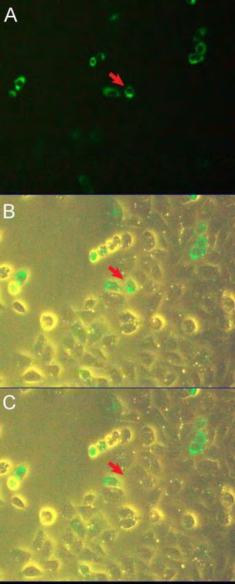
29When collecting fluorescently labeled cells (Figure 4),
calibrate the DCU under bright field as described above,
and then turn off LED ring light. Turn on the
fluorescent illumination to locate desired labeled cells.
Turn fluorescent illumination off to prevent bleaching
of cells. After collecting the cell, fluorescent
illumination may be turned on again and the process
repeated.
NOTE: Optimal vacuum levels and duration can vary
depending on the type of cell cultures and confluence
of the cells. It is recommended that a test cell culture
dish be used to determine the optimal values of
vacuum level and duration prior to sampling. Start at
the lowest settings for vacuum level and duration and
slowly increase them in turn.
Figure 4: Collecting fluorescently labeled cells. A:
Initial identification of fluorescently labeled cells under
fluorescent illumination. B: Under bright field
fluorescent label is still visible. Bright field may be used
to position the cell of interest under the crosshair for
collection and to visualize cell collection into the DCU.
Fluorescent illumination should be turned off to prevent
bleaching of label prior to sampling. C: Upon collecting
the cell, turn on fluorescent illumination to resume
collection.
NOTE: Change the DCU and filter after each collection
procedure. DCUs may be reused by washing with a
syringe and sterilizing with ethanol. DCUs can also be autoclaved. However, NeuroInDx
recommends using a new DCU for each collection procedure to avoid contamination.
30You can also read