Colliders and The Large Hadron Collider - LHC layout II. LHC Operational cycle III. Beam measurements - CERN Indico
←
→
Page content transcription
If your browser does not render page correctly, please read the page content below
[R. Alemany]
 [CERN BE/OP]
 Lectures ULB (05.02.2021)

Colliders and The Large Hadron Collider
 I. LHC layout
 II. LHC Operational cycle
 III. Beam measurements
Why colliders?
What is the centre of mass energy è the interesting energy because it is the only
one available for the collision products è when two particles of masses m1 and m2
collide? Square of the four-momentum:
 Four-momentum

 CASE 1:
 (m1,p1)
 (m2,0)

 CASE 2:
 (m1,p1) (m2,-p1)
 05.02.2021
Why colliders?
CASE 1:

To get a Ecm = 630 GeV to do a SppS collider (SPS in the 80’s discovered the weak
neutral currents with this collider), what should be the value of E1,lab?
 E1,lab ~ 212 TeV
To get a Ecm = 14 TeV to do an LHC collider (LHC discovered the Higgs in 2012)
what should be the value of E1,lab?
 E1,lab ~ 100 PeV
 First collider
If colliders would not have
been invented we would not
have been discovered yet
many particles

 05.02.2021
Why colliders?

 From the point of view of the energy, a collider is very very interesting
 However it has some disadvantages:

 1. The beam is several orders of magnitude less dense than a fixed
 target è less number of interactions per second
 • How do we overcome this issue?
 We collide for many hours è e.g. LHC collisions ~ 12 – 15 hours

 2. The collision products go out in all directions è experiment has to cover
 all the space around the beam pipe
 • Experiments located around the beam pipe are difficult to take in/out
 to install a new experiment.
 • Fixed target experiments are more flexible, e.g. SPS north area: tens
 of experiments per year.

05.02.2021
I. Basic layout of the machine

 Betatron
 cleaning
 collimators

 IP8
 IR7 IP1
 IR6
 SPS (~7 km)
 IP5 LHC (27 km) IP2

 Sector 34 Momentum
 cleaning
 collimators
05.02.2021
 IR4 ARC
 IR3
I. Basic layout of the machine:
 the arc
 LHC arc cells = FoDo lattice* with
 ~ 90º phase advance per cell in the V & H plane

 o o
 F D
 B1

 F B2
 D

 LHC TDR

 MB: main dipole
 MQ: main quadrupole
 MQT: Trim quadrupole
 MQS: Skew trim quadrupole
 MO: Lattice octupole (Landau damping)
 MSCB: Skew sextupole +
 Orbit corrector (lattice chroma+orbit)
 MCS: Spool piece sextupole
 MCDO: Spool piece octupole +
05.02.2021 Decapole
 BPM: Beam position monitor
I. Basic layout of the machine
Golden formula (you should know by heart) Circumference è FIXED!!! by LEP

 26658.9
 ≈ , 66% ≈ 2780
 2

 ~ 66% of the lattice elements are dipoles

 p = nucleon momentum è defined by
 the physics case è TeV range è 7 TeV

 We need SUPERCONDUCTING technology
 05.02.2021 Field limit for normal conducting
 magnets due to saturation
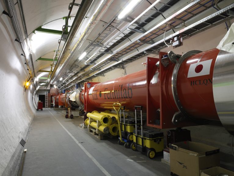
I. Basic layout of the machine:
 Superconducting magnets
 Superconducting cables of Nb-Ti
 6 µm Ni-Ti He gas è liquid @ 4.2 K è superfluid
 filaments @ 2.17 K
 10000
 SOLID

 1 mm 1000

 CRITICAL POINT
 l line
 HeII HeI

 P [kPa]
 100
 Pressurized He II

LHC ~ 27 km circumf. with 20 km of GAS

superconducting magnets operating 10

@8.3 T. An equivalent machine with Saturated He II λ point
normal conducting magnets would have 1
a circumference of 100 km and would 1 10
consume 1000 MW of power è we T [K]

would need a dedicated nuclear power
station for such a machine. LHC
 05.02.2021
 Total amount of He used @LHC
 ~500-700 T
consumes ~ 10% nuclear power station
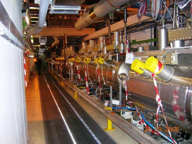
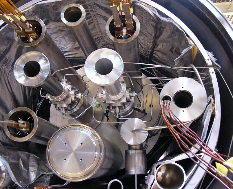
I. Basic layout of the machine:
 main cryodipoles (two dipoles in one)
 • The geometry of the main dipoles (Total of 1232 cryodipoles)
 Heat
 exchanger

 Beam pipe (Ultrahigh beam
 vacuum 10-10 Torr like at
 1000 km over see level) Collars
 Beam Screen Cold bore
(Stainless Steel non-magnetic
 + Cu) austenitic
 steel

 36.9 mm He Vessel

 46.5 mm Thermal
 Iron shield
 yoke
Superconducting Vacuum
 coils vessel (10-6
 mbar)

 L ~ 15 m
 05.02.2021 8.3 T, 11.87 kA
 T = 1.9 K, ~27.5 ton
I. Basic layout of the machine:
 main quadrupoles
 55 per sector

 56 mm (warm)

 194 mm (cold)

 Integrated gradient = 690 T
 Nominal gradient = 223 T/m
 Inominal = 11.87 kA
 L=3.1 m

05.02.2021
I. Basic layout of the machine: tough
 main dipoles èField quality
The magnetic field of the main dipoles:
The stability of the geometry of the superconducting
coils is essential to the field quality.
Mechanical stress during coil assembly
 = sources of deformations
Thermal stresses during cool-down of the coil geometry
Electromagnetic stresses during operation
Additional sources of field errors are the dimensional tolerances of the
 magnet components and of the manufacturing and assembling tooling.

The relative variations of the integrated field and of the field shape
 imperfections must not exceed ~ 10 -4 and

05.02.2021
I. Basic layout of the machine:
 main dipoles èField quality
Why the tolerances are so tight?
è Because the field quality determines how long the
 particles can circulate in the accelerator

Up to which order do we care?
05.02.2021
è Up to n = 7 at least ~ 10-4
I. Basic layout of the machine:
 main dipoles èField quality
Error Side effects if error is > few 10-4 Corrected with
a1 Closed orbit perturbations and thus feed-down Dipole correctors (MCB)
b1 contributions from higher order multiple errors

a2 Linear coupling and vertical dispersion Skew quadrupoles (MQS)
b2 Tune change, β and dispersion beating Trim quadrupoles (MQT)
a3 Chromatic coupling and Q’’ Skew sextupoles (MSS)
b3 b2 feed-down at injection (persistent current Sextupole (MCS)
 effect) and off-momentum β-beat
a4 Dynamic aperture (DA) at injection
b4 DA and Q’’ at injection Octupole (MCO)
a5 DA for off-momentum particles at injection
b5 DA and Q’’’ at injection Decapole (MCD)
a6 to DA at injection Sextupole

b7
05.02.2021
 Sextupole+octupole
I. Basic layout of the machine:
 dipole corrector magnets
 o o
 F D

 LHC TDR
MCS MCDO
 5.8 cm

 MCD: MCO:
Nominal main field Nominal main field Nominal main field
strength = 1630 T/m2 strength ~ 120 T/m4 strength = 8200 T/m3
 05.02.2021 Inominal = 550 A, 1.9 K, Inominal = 100 A, 1.9 K,
Inominal = 550 A, 1.9 K,
L=15.5 cm, ~10 kg L=11 cm, ~6 kg L=11 cm, ~6 kg
I. Basic layout of the machine:
 quadrupole corrector magnets
 o o
 F D

 LHC TDR
 MSCB
 MQT/MQS
 Landau damping MQT: Trim
 MO quadrupole
 MQS: Skew trim
 quadrupole
 MQT/MQS:
 Nominal main field
 strength = 123 T/m
MSM (sextupole): MCBM (dipole): MO: Inominal = 550 A, 1.9 K
Nominal main field Nominal main field Nominal main field L=38 cm, ~250 kg
strength = 4430 T/m2 strength = 2.93 T strength = 63100 T/m3
 05.02.2021
Inominal = 550 A, 1.9 K, Inominal = 55 A, 1.9 K, Inominal = 550 A, 1.9 K
L=45.5 cm, ~83 kg L=78.5 cm, ~143 kg L=38 cm, ~8 kg
I. Basic layout of the machine:
 quadrupole corrector magnets

(Courtesy of B. Holzer)

F o D o Why the orbit and sextupole correctors
 are placed close to a quadrupole?

 LHC TDR

 05.02.2021
I. Basic layout of the machine:
 quadrupole corrector magnets
 1
 b ( s) * ò b * cos(y s1 -y s - pQ ) ds
 β (m) r s1 s1
 xco ( s ) =
 2 sin pQ
 Magnet
 strength

 QF

 D (m)

 1
 Q' = -
 4p òk qua ( s ) b ( s )ds + (Natural chromaticity term)

 1
 +
 4p
 å sext sext x x -
 k focu

 FocuSext
 l D focu
 b focu

Chromaticity correction terms
 1
 05.02.2021
 -
 4p
 å sext sext x b x
 k defocu

 DeFocuSext
 l D defocu defocu
I. Basic layout of the machine

 Betatron
 cleaning
 collimators

 IP8
 IR7 IP1
 IR6
 SPS (~7 km)
 IP5 LHC (27 km) IP2

 Sector 34 Momentum
 cleaning
 collimators
05.02.2021
 IR4 ARC
 IR3
I. Basic layout of the machine:
 Dispersion suppression
 ARC DS LSS
 Q11 Q10 Q9 Q8
 empty

 MBARC
 The schema applies to all DS except the ones in IR3 and IR7

• Cancels the horizontal dispersion generated on one side by the arc dipoles and on
 the other by the separation/recombination dipoles and the crossing angle bumps
• Helps in matching the insertion optics to the periodic solution of the arc
• If only dipoles are used they cannot fully cancel the dispersion, just by a factor 2.5.
 Therefore individual powered quadrupoles are required (Q8-Q11 with I ~ 6000 A)

 05.02.2021
 (Courtesy of B. Holzer)
I. Basic layout of the machine:
 Dispersion suppression
Dispersion (m)

 D(s) is created by the
 ARC dipole magnets and
 2m DISPERSION SUPPRESION
 afterwards focused
 0m
 by the quadrupoles

 Direction IP5

 The inhomogeneous solution changes the beam size …

 When you design your beam pipe you have to
 take into account the contribution of D(s)
 05.02.2021
 Why do we suppress dispersion before reaching the IP?
I. Basic layout of the machine

 Betatron
 cleaning
 collimators

 IP8
 IR7 IP1
 IR6
 SPS (~7 km)
 IP5 LHC (27 km) IP2

 Sector 34 Momentum
 cleaning
 collimators
05.02.2021
 IR4 ARC
 IR3
I. Basic layout of the machine:
 Luminosity insertions
 ATLAS
 Inner Triplet Separation/ Recombination Matching Quadrupoles DS
 R1 Q1 Q2 Q3 D1 Tertiary D2 Q4 Q5 Q6 Q7

 TAN*
 TAS*
 (1.38 T) collimators (3.8 T)
 IP1

 188 mm
 1.9 K Warm 1.9 K

 4.5 K

 4.5 K

 4.5 K
 6.45 kA 10.63 kA

 Q2 Q3

 Q1
 23.85 29.0 22.5 To provide sufficient aperture for the Xangle
 18.95 24.0 17.6

* Protect Inner Triplet (TAS) The mechanical aperture of the inner triplets limits the
and D2 (TAN) from particles
 05.02.2021
coming from the IP
 maximum b* @IPs and the maximum Xangle è limit peak lumi
Two figures of merit in a collider:
 Luminosity energy and luminosity

Luminosity = number of interactions per unit of time
 cross-section at the given energy of the
 interested physics
 h

 h
 l l
Number of particles of the first beam in the cube: The orange beam is crossed by n2
 particles per unit of time:

 05.02.2021
 with I = q/t t
Luminosity
The number of events per unit of time for two beams of 1 cm2 is:

 and for beams of a general area s = wh

 If we replace q = 1.6e-19 coulomb and c = 3e10 cm/s:

 05.02.2021
Luminosity for bunched beams

 For two bunches colliding HEAD ON with Gaussian beam density distribution
 and equal beam sizes:

 Ni: number of particles in one bunch
 Reference:
 f: revolution frequency
 Nb: number of bunches in one beam
 sigma: beam size
05.02.2021
05.02.2021
Luminosity for bunched beams
 Examples:

05.02.2021
I. Basic layout of the machine:
 Luminosity insertions
 D2 D2

 D1 Q3 Q2 Q1 Q1 Q2 Q3 D1
 IP

05.02.2021
I. Basic layout of the machine:
 Luminosity insertions

 D2 D2

 D1 Q3 Q2 Q1 Q1 Q2 Q3 D1
 IP

 With nominal LHC parameters:
 2808 bunches separated 25 ns

 We can have up to 30 parasitic interactions around the IP

05.02.2021
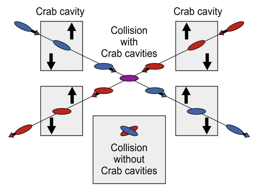
I. Basic layout of the machine:
 Luminosity insertions

 D2 D2

 D1 Q3 Q2 Q1 Q1 Q2 Q3 D1
 IP

 Crossing angle reduces the luminosity

05.02.2021
I. Basic layout of the machine:
 Luminosity insertions

 D2 Aperture limitation D2

 D1 Q3 Q2 Q1 Q1 Q2 Q3 D1
 IP

 Crossing angle (e.g. 285 µrad )

 Beam-beam separation

 Beam-beam separation = f(σ)
 Aperture limitation = f(σ, beam pipe size)

 β is very small at the IP, but very big at the Inner triplets è

 Therefore, the
05.02.2021 quadrupoles around the IP have such a big apertures
I. Basic layout of the machine:
 Luminosity insertions

LHC crossing angle of around 300 µrad è luminosity reduction factor in LHC ~ 20%

05.02.2021
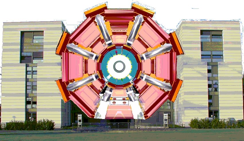
I. Basic layout of the machine:
 High luminosity insertions
 ATLAS
 CMS

five-storey building

 05.02.2021
II. LHC Operational cycle
 ~ 2 hours

 RAMP FLATOP
 Exp-LHC

 INJECTION PHYSICS
 INJECTION PROBE

 PREPARE RAMP
 RAMPDOWN
Current (A)

 SQUEEZE
 SETUP

 ADJUST
 STABLE BEAMS…

 10 to 15 hours

 RB.A12
 RQ6.L1

 Time
 05.02.2021
II. LHC Operational cycle:
 Squeeze è reduce β*
 Squeeze the beam size down
 as much as possible at the
 collision point to increase
 the chances of a collision
 N1 N 2 f rev N b
 L»
 4ps 2
• So even tough we squeeze our N1,2=100,000 million protons per bunch
 down to 16 microns (1/5 the width of a human hair) at the interaction
 point. We get only around 20 collisions per crossing with nominal
 beam currents.
• The bunches cross (every 25 ns) so often we end up with around 600
 million collisions per second - at the start of a fill with nominal current.
• 05.02.2021
 Most protons miss each other and carry on around the ring. The beams
 are kept circulating for hours è 10 hours
II. LHC Operational cycle:
 Squeeze è reduce β* (β @IP)
 Beta function at Injection Beta function at top energy and after squeeze
 4500 m
 180 m IR1 IR5 IR1
 250 m
 IR5

 180 m

 IR1 IR2 IR3 IR4 IR6 IR7 IR8 IR1 IR2 IR3 IR4 IR6 IR7 IR8

Why we cannot have β*= 0.5 m at injection? @IP β*=0.5 m
 Rbeampipe~29/24 mm
 β=4500 m we could only
 g(@450 GeV)~480 accommodate ~ 4
 εn=3.5 µm rad times the beam size
 and we need at least
Remember: 7σ clearance
 there is no σ ~ 6 mm !!
 D(s) here @ 7 TeV
 05.02.2021
 σIT ~ 1.2 mm
II. Beam measurements:
 Beam trajectory

 Betatron oscillation

Each point is a BPM
 (Beam Position
 Measurement) A B
 beam
 ARC BPMs
 05.02.2021
 TA TB 49 mm aperture
II. Beam measurements:
 Beam trajectory correction

MSCB

 F o D o

 LHC TDR

 05.02.2021 Why the orbit and sextupole correctors
MSM (sextupole) are placed close to a quadrupole?
 MCBM (dipole)
II. Beam profile measurements:
Beam 1 on TDI screen – 1st and 2nd turns

 Scintillator screen for LBDS

 ALICE
 05.02.2021
II. Beam profile measurements:
 Emittance measurement - Wire scanner
 Emittance is the figure of merit for profile measurements.
 But it is a derived quantity from the beam size ( = )
Where would you install a wire scanner in LHC to get the
 beam size and then the emittance?

 s è e = s2/β

 05.02.2021
 Which we measured before
 Courtesy of A. Guerrero
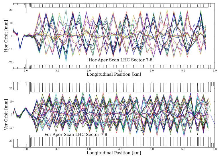
II. Beam measurements:
 Aperture scan

 BLM*

05.02.2021
 *Beam Loss Monitor = Ionization chamber
II. Beam measurements:
 Dispersion measurement
Horizontal Dispersion (m)

 OFF-MOMENTUM
 D(s) = 0 m IR3 particles cleaning system
Vertical Dispersion (m)

 Dp
 Dx = Dx ( s)
 05.02.2021 p
 RF
II. Beam measurements:
 Beta measurement
 1st Change quadrupole strength in steps

 2nd Measure Tune

 3rd Plot Tune vs Quadrupole strength

 Qx,Qy

 kL
05.02.2021
 Courtesy of B. Holzer (lectures)
II. Beam measurements:
 Fast BCT (Beam Current Transformer)

 FBCT

 Each point is a bunch B1
 Total number of bunches = 1380
 ~ 3 109
 Intensity

 B2

05.02.2021
SPARE SLIDES

05.02.2021
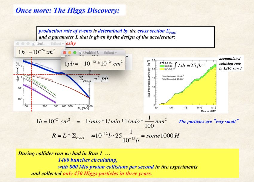
High Light of the LHC

 production rate of events is determined by the cross section Σreact
 and a parameter L that is given by the design of the accelerator:
 … the luminosity
 1
 R = L * S react »25 10 -12 b = some 1000H
 10 -15 b
 remember:
 1b=10-24 cm2
 Sreact »1 pb

Integrated luminosity during RUN I
 ò Ldt »25 fb-1
 Official
 05.02.2021 number: 1400 clearly identified Higgs particles “on-tape”
 41/42
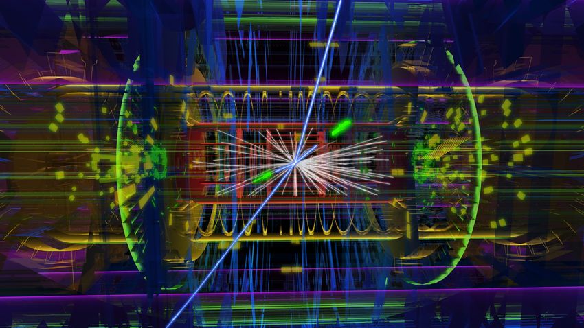
High Light of the HEP year

 ATLAS event display: Higgs => two electrons & two muons
05.02.2021
 42/42
I. Basic layout of the machine:
Superconducting magnets

• Superfluid helium è Why is it so great?!!
 • very high thermal conductivityè is able to
 conduct away heat a thousand times better than a
 metallic conductor like copper
 • very low viscosity coefficient è can penetrate
 tiny cracks, deep inside the magnet coils to absorb
 any generated heat
 • very high heat capacity è prevents small
 transient temperature fluctuations

05.02.2021
XIV. Beam captured – mountain range
display
 Turn number

 Now RF ON

05.02.2021 Bunch length ~ 1.5 ns è ~ 45 cm
Beam parameters (nominal)
 Injection Collision 2012
Proton energy GeV 450 7000 4000
Particles/bunch 1.15 x 10¹¹ 1.6 x 10¹¹
Num. bunches 2808 1380
Longitudinal emittance (4s) eVs 1.0 2.5
Transverse normalized emittance µm rad 3.5 3.75
Beam current A 0.582
Stored energy/beam MJ 23.3 362

 b* = 0.55 m Peak luminosity related data
RMS bunch length e = 0.5 nm rad cm 11.24 7.55
 b* = 0.6 m
RMS beam size @IP1 & IP5 è sx,y = Öeb µm 375.2 16.7
 en = 2.5 µm
RMS beam size @IP2 & IP8 è sx,y = Öeb µm 279.6 70.9 rad
Geometric luminosity reduction factor (F) 0.836
Instantaneous lumi @IP1 & IP5 (IP2Pb-Pb, IP8) cm-2s-1 1034(1027 , 7 1033
 05.02.2021 1032)
pPb physics during 2013
 On momentum orbit Off momentum orbit

 + 250 μm
 5 kHz p+
 difference
 at injection

 - 250 μm
 Pb82+208

05.02.2021
05.02.2021
05.02.2021
I. Basic layout of the machine:
 main cryodipoles (two dipoles in one)
 • The geometry of the main dipoles (Total of 1232 cryodipoles)
 VERTICAL HORIZONTAL
 PLANE PLANE
 Length of the bend
The theoretical part =14.3 m
shape of the
beam channels is
a straight line,
while the natural
shape has ~ 0.3 ρ = 2.8 km
mm deflection (R = 4.3 km)
between two
supports at 5.4 m L ~ 15 m
 Distance between
distance 8.3 T, 11.87 kA apertures = 194.5 mm
 T = 1.9 K, ~27.5 ton
 The active part of the cold mass is bent
 in the horizontal plane with an angle of
 05.02.2021 5.09 mrad with ρ = 2.8 km. The shape of
 the two beam channels is identical.
II. The experiments:
 Low luminosity insertions: LHCb
 Centre of the exp cavern

05.02.2021
IV. Momentum and betatron
 cleaning insertions (IR3, IR7)

 ±50s ±14s
 ±6(9)s ±7s ±8.5s

 Settings @7TeV and b*=0.55 m
05.02.2021 Beam size (s) = 300 µm (@arc)
 Beam size (s) = 17 µm (@IR1, IR5)
I. Basic layout of the machine:
 quadrupole corrector magnets

05.02.2021
II. LHC Operational cycle:
 Squeeze è reduce β*
 IT MS DS
 Q1 Q3 D2 Q5 Q7 Q8 Q9 Q10 Q11

 2MB
 2MB
 2MB
 2MB
 Q2 D1 Q4 Q6

 ATLAS=CMS

 Remember what I said in slide 23
 è The mechanical aperture of the
 inner triplets limits the maximum
 b* @IPs and the maximum
 Xangle è limit peak luminosity

05.02.2021
II. Beam measurements:
 Integer tunes

 Qx = 64

 Qy = 59

05.02.2021
I. Basic layout of the machine:
 Dispersion suppression
• Quadrupole types: MQ, MQM, MQTL
 MQM

 5m

 Nominal gradient = 200/160 T/m
 Inominal = 5.4/4.3 kA
 Lmag=2.4/3.4/4.8 m
 T=1.9/4.5 K
 Cold bore = 53/50 mm
05.02.2021
 Individual powered apertures
 18/42
I. Basic layout of the machine:
 Low luminosity insertions
LHCb ALICE

 Beam 1

 Beam 2

 LHCb
 Q1 Q2 Q3 D1
 TCDD

 D2 Q4 Q5 Q6 Q7
 IP8 TDI
 Beam 2

 MKI Beam 1 MSI

 Extra
 05.02.2021 challenge è the lattice has to accommodate the injection region
 26/42
I. Basic layout of the machine
 LHC arc cells = FoDo lattice* with
 ~ 90º phase advance per cell in the V & H plane

 o o
 F D

 LHC TDR

 Which parameter determines the beam size (ignoring D(s))?
 6 = 7 7 + 9 9
 (In general in proton machines εx≈εy è beams are round)

 In order to get the maximum aperture possible the β(s) in both
σinjβ ~1 mm planes have to be minimized:

05.02.2021
 27/42
II. Beam measurements:
 Beta measurement

 Achieved β-beating error 10% !!

 05.02.2021
Reference: Record low beta beating in the LHC
Tomas, R. et al. Phy. Rev. Special Topics - Accelerators and Beams15(9). 38/42
II. Beam measurements:
 Non-integer tunes
 FODO: Ψ=180o
 Every 2xT we measure the
 same position:
 F/2 D F/2 1 1
 = = = , = , ?@A
 2
 → = 0.5
 BPM
BPM pos è FFT è tune
 With a frequency of ~3 kHz
 we measure the same
 A B beam position
 beam

 Qx·frev = 3 kHz
 TA TB

 Qx = .279 @LHC
05.02.2021
 Qy = .310 39/42
You can also read