Corrosion and corrosion prevention in heat exchangers - UGent Biblio
←
→
Page content transcription
If your browser does not render page correctly, please read the page content below
Corros Rev 2019; aop

Willem Faes*, Steven Lecompte, Zaaquib Yunus Ahmed, Johan Van Bael, Robbe Salenbien,
Kim Verbeken and Michel De Paepe

Corrosion and corrosion prevention in heat
exchangers
https://doi.org/10.1515/corrrev-2018-0054
Received June 22, 2018; accepted December 13, 2018
                                                                    1 Introduction
Abstract: In many industries and processes, heat exchang-           Heat exchangers are devices used to transfer thermal
ers are of vital importance as they are used to transfer heat       energy over a heat transfer surface from one fluid to a
from one fluid to another. These fluids can be corrosive            second fluid at a lower temperature (Kakaç et al., 2012).
to heat exchangers, which are usually made of metal-                Several types of heat exchangers exist, but the most
lic materials. This paper illustrates that corrosion is an          common types (the focus of this paper) are shell-and-tube
important problem in the operation of heat exchangers in            heat exchangers and plate heat exchangers.
many environments, for which no straightforward answer                   In a shell-and-tube heat exchanger, a number of tubes
exists. Corrosion failures of heat exchangers are common,           are mounted in a cylindrical shell, parallel to the axis of
and corrosion often involves high maintenance or repair             the shell (Kakaç et al., 2012). Typically, several vertical
costs. In this review, an overview is given of what is known        plates, baffles, are inserted in the shell to redirect the flow
on corrosion in heat exchangers. The different types of             over the tubes and to improve the heat transfer. A sche-
corrosion encountered in heat exchangers and the suscep-            matic representation is given in Figure 1, where a cold
tible places in the devices are discussed first. This is com-       fluid flows through the tubes and a hot fluid flows through
bined with an overview of failure analyses for each type            the shell.
of corrosion. Next, the effect of heat transfer on corrosion             Plate heat exchangers consist of a number of thin
and the influence of corrosion on the thermohydraulic               plates, mounted behind each other in a frame (Kakaç
performances are discussed. Finally, the prevention and             et al., 2012). A gasket is placed between two adjacent
control of corrosion is tackled. Prevention goes from gen-          plates to determine the flow path and to prevent the fluid
eral design considerations and operation guidelines to the          from leaking to the environment. The plates are typically
use of cathodic and anodic protection.                              corrugated to improve the heat transfer. The working prin-
                                                                    ciple is illustrated in Figure 2.
Keywords: corrosion; geothermal; heat exchangers; heat
                                                                         Heat exchangers play a key role in the operation of
transfer.
                                                                    various industrial processes like the oil and gas industry,
                                                                    the chemical and pharmaceutical industry, petroleum
                                                                    refining, and the pulp and paper industry. In each of these
                                                                    industries, the heat exchanger can be subject to a variety
                                                                    of environments. Some of them are known to be aggres-
                                                                    sive, while others are often not considered to be corrosive.
                                                                    It was calculated in 2001 that the direct cost of all types of
*Corresponding author: Willem Faes, Department of Flow, Heat        corrosion in the United States amounts annually to $276
and Combustion Mechanics, Ghent University, Ghent, Belgium; and     billion or 3.1% of the gross domestic product of the country
Flemish Institute of Technological Research (VITO), Mol, Belgium,   (Koch et al., 2002). Of these costs, $17.6 billion are allocated
e-mail: willem.faes@ugent.be
                                                                    to production and manufacturing businesses, under which
Steven Lecompte and Zaaquib Yunus Ahmed: Department of Flow,
Heat and Combustion Mechanics, Ghent University, Ghent, Belgium     the aforementioned industries are categorised. For electri-
Johan Van Bael and Robbe Salenbien: Flemish Institute of            cal power generation, in which heat exchangers are also
Technological Research (VITO), Mol, Belgium; and EnergyVille,       frequently used, the annual corrosion cost is estimated
Thor Park, Genk, Belgium                                            in the same study at $6.9 billion. In a more recent study
Kim Verbeken: Department of Materials, Textiles and Chemical
                                                                    by NACE International (2016), it was calculated that the
Engineering, Ghent University, Ghent, Belgium
Michel De Paepe: Department of Flow, Heat and Combustion
                                                                    annual global cost of corrosion amounts to $2.5 trillion.
Mechanics, Ghent University, Ghent, Belgium; and Flanders Make,          According to other sources (Electric Power Research
Core Lab UGent-EEDT, www.flandersmake.be, Lommel, Belgium           Institute, 2001; Syrett & Gorman, 2003; Roberge, 2008),

                                                                              Authenticated | willem.faes@ugent.be author's copy
                                                                                               Download Date | 3/14/19 10:31 AM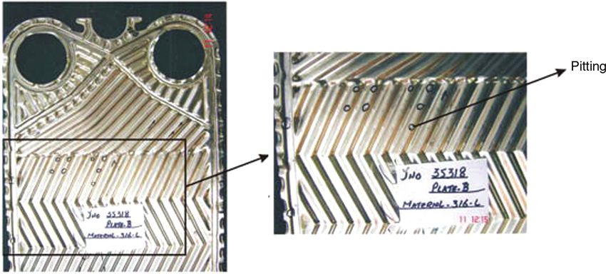
2         W. Faes et al.: Corrosion and corrosion prevention in heat exchangers

                                                                       In addition to these economic issues, Davis (2000) also
                                                                       gave some examples of social consequences:
                                                                       –– Safety (e.g. risk for explosions);
                                                                       –– Health (e.g. escaping of a poisonous product from a
                                                                           corroded heat exchanger);
                                                                       –– Depletion of natural resources;
                                                                       –– Visually unpleasant appearance;
                                                                       –– Environmental contamination.

                                                                       That a failing heat exchanger can pose a potential safety
                                                                       threat was illustrated by Collier (1983). According to the
Figure 1: Schematic representation of a shell-and-tube heat            author, explosion of boilers (a thermal system analogous to
exchanger.                                                             a shell-and-tube heat exchanger) used in American steam-
                                                                       boats occurred at least 233 times between 1816 and 1848,
                                                                       which in total caused the death of 2560 passengers and left
the total cost of corrosion for the electrical power industry          2100 others injured. One major accident was the explosion
was $15.4 billion in the United States in 1998. This amount            of the Sultana steamboat on the Mississippi River in 1865,
is split into categories, where corrosion of heat exchangers           resulting in >1250 deaths (Yager, 1976). Jennings (2015)
takes up 5.55% or $855 million annually. These high losses             stated that the boiler in this steamboat was made from
are a combination of direct and indirect costs caused by               wrought iron that most likely contained inclusions and
corrosion and can be attributed to several economic con-               imperfections resulting from the production techniques
sequences (Davis, 2000), as follows:                                   from that period. These are sites where corrosion could
–– Replacement of corroded equipment;                                  initiate, and therefore Jennings claimed that possibly cor-
–– Oversizing to take possible corrosion into account;                 rosion at these sites was the root of the tragic incident. The
–– Preventive maintenance;                                             explosion of land-based boilers was a common problem
–– Shutdown of equipment;                                              as well. In his publication, Collier (1983) also emphasised
–– Loss of efficiency (e.g. when corrosion products                    on the fact that between 1890 and 1904, 5000 incidents of
     decrease the heat transfer rate of the heat exchanger);           such explosions were reported by one insurance company.
–– Loss of a product (e.g. through leakages or contamina-                   Although the knowledge about heat exchangers
     tion of a product).                                               and the existing production techniques have drastically
                                                                       improved, accidents caused by corrosion still occur. Two
                                                                       more recent failures of heat exchangers, illustrating the
                                                                       potentially catastrophic consequences, were reported
                                                                       on an offshore gas production platform in 2006 and in a
                                                                       refinery plant in 2010.
                                                                            In the first incident, a shell-and-tube heat exchanger,
                                                                       made from carbon steel clad with titanium, was used to
                                                                       cool hydrocarbon gas with seawater (Health and Safety
                                                                       Executive, 2006; Parrott, 2014). Galvanic corrosion
                                                                       between the carbon steel and titanium cladding caused
                                                                       the escape of the gas into the seawater, overpressuring the
                                                                       shell. The shell and the tubes got torn from the tube sheet
                                                                       and the escaping gas exploded. Luckily, there were only
                                                                       two minor injuries. The second incident was a carbon steel
                                                                       shell-and-tube heat exchanger, but with a stainless-steel
                                                                       type 316 liner [U.S. Chemical Safety and Hazard Investiga-
                                                                       tion Board (CSB), 2010; Marsh, 2016]. The shell ruptured
                                                                       at the weld seams, releasing the hot hydrogen and naptha.
Figure 2: Plate heat exchanger with indicated flow paths.
Republished with permission of Taylor & Francis Group LLC, from
                                                                       The mixture autoignited, resulting in seven fatalities. The
Kakaç et al. (2012); permission conveyed through Copyright             root cause of the accident was determined to be high-
Clearance Center, Inc.                                                 temperature hydrogen attack (HTHA) of the carbon steel.

                                                                                  Authenticated | willem.faes@ugent.be author's copy
                                                                                                   Download Date | 3/14/19 10:31 AM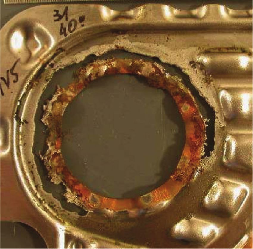
W. Faes et al.: Corrosion and corrosion prevention in heat exchangers       3

Both galvanic corrosion and hydrogen damage in heat
exchangers will be discussed later.
    In the literature, various failure analyses can be found
where heat exchangers suffered corrosion. According to
the authors’ knowledge, no paper gives an overview or
describes the particularities of the corrosion processes
occurring in heat exchangers. Therefore, this study gives
a non-exhaustive overview of the failures, to show which
types of corrosion are common and which places are sus-
ceptible. As the research on either the influence of heat
                                                                Figure 3: Schematic representation of the corrosion process of iron-
transfer on corrosion, or vice versa, is scattered, this is
                                                                based alloys in aqueous solutions.
described in a next section. Based on recommendations
given in the failure analyses and heat exchanger design
handbooks, guidelines are provided on how to prevent cor-       2.1 Uniform corrosion
rosion in heat exchangers. Additionally, two more special-
ised corrosion protection techniques, cathodic and anodic       When corrosion is homogeneously spread over the entire
protection, are discussed. A great deal of the information      heat transfer surface, the term “uniform corrosion” is
about these methods was found in the patent literature.         used. Uniform corrosion is usually easy to detect visually.
    The many failures discussed in this paper demo-             The thinning of the tube or plate increases the stresses in
nstrate that corrosion is a challenging problem in the          the metal, which might eventually lead to failure (Wang
operation of heat exchangers. Most failures are caused by       et al., 2007). One strategy to avoid this type of corrosion
localised forms of corrosion, such as pitting or stress cor-    is by selecting a material that passivates in the specific
rosion. To prevent this, careful material selection, design     environment. Alternatively, by doing exposure tests prior
phase, and operation are absolute prerequisites to guar-        to the use of the heat exchanger, the corrosion rate can
antee a long lifetime of the heat exchanger. Electrochemi-      be determined (expressed, e.g. in mm/year), which allows
cal techniques exist to limit corrosion of heat transfer        designing the heat exchanger with an increased wall
surfaces (cathodic and anodic protection). Their applica-       thickness (Revie & Uhlig, 2008).
tion in heat exchangers is, however, not straightforward.            This does not imply that uniform corrosion does not
                                                                pose any problems. For example, different uniform cor-
                                                                rosion rates in different parts of the exchanger are prob-

2 T
   ypes of corrosion encountered                               lematic for overhauling. In the case described by Xie et al.
                                                                (2015), the carbon steel tubes of a vertical shell-and-tube
  in heat exchangers                                            heat exchanger, used to cool a stripper overhead vapour,
                                                                had to be replaced after only 2.5 years of service (Xie
Corrosion is a term used to describe the (unwanted) deg-        et al., 2015). Around the tubes, cooling water flowed,
radation of a metal when exposed to an environment, due         which cooled the process vapour inside the tubes. Brown
to interaction with this environment. Most of the exam-         and reddish rust was found on both internal and exter-
ples discussed below involve aqueous environments. The          nal surfaces, and severe wall losses (>70% for 159 of the
corroding metal in the liquid is called the anode, and the      1410 tubes) were detected. Figure 4 shows a cross section
metal ions go into solution following the anodic oxidation      of different tubes. Signs of corrosion can be seen on both
reaction. Corrosion is only possible if the electrons result-   external and internal surfaces, and the difference in wall
ing from this reaction are consumed by a cathodic reaction      thickness can clearly be observed. The authors discov-
(e.g. the reduction of dissolved oxygen). An electrically       ered that the corrosion was most severe just underneath
conductive path must exist between the two locations            the top tube sheet. This was explained by the accumula-
for the electrons to pass (Edwards, 2013). This corrosion       tion of non-condensable gases at the top of the shell area,
process is illustrated in Figure 3. Many types of corrosion     causing the concentration of corrosive elements (e.g. chlo-
are possible, depending on the material, the environment,       rides) in the water on the hot tube surfaces at the vapour-
and the working conditions (Roberge, 2000). In the next         liquid interface.
sections, the most prevalent forms encountered in heat               The uniform corrosion was more severe at the cooling
exchangers are discussed and several examples of failures       water side than at the internal surface of the tubes.
of heat exchangers, caused by corrosion, are presented.         However, uniform corrosion was not the only type of

                                                                           Authenticated | willem.faes@ugent.be author's copy
                                                                                            Download Date | 3/14/19 10:31 AM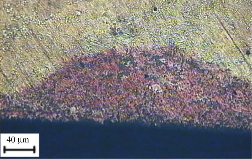
4         W. Faes et al.: Corrosion and corrosion prevention in heat exchangers

                                                                       as the application of a coating) are often susceptible to
                                                                       pitting (Revie & Uhlig, 2008). At mechanical defects of
                                                                       this protective layer, pits are initiated, and when these
                                                                       grow sufficiently, they might perforate the heat transfer
                                                                       surface. The initiation of pitting is influenced by metal-
                                                                       lurgical and structural factors, environmental factors,
                                                                       polarisation phenomena, and the presence of corrosion
                                                                       products. For stainless steel, high chloride content, high
                                                                       temperatures, and low pH are promoters of pitting corro-
                                                                       sion. Some metals often used in the construction of heat
                                                                       exchangers whose protective film might locally break
                                                                       down, and as such initiate pitting, are other passivating
                                                                       metals such as aluminium, nickel, titanium, and their
                                                                       alloys (Kuppan, 2000).
                                                                            The tendency of a stainless steel to be susceptible to
                                                                       pitting corrosion can be predicted with the pitting resist-
                                                                       ance equivalent number (PREN). This number can be
Figure 4: Section of the tube with severe uniform corrosion and wall
                                                                       calculated with Eq. (1) based on the mass fraction (in per-
thickness reduction.                                                   centage) of chromium (Cr), molybdenum (Mo), tungsten
Reprinted with permission from NACE International, from Xie et al.     (W), and nitrogen (N) in the alloy (Roberge, 2000). The
(2015).                                                                common type of stainless steel, type 304, has a PREN of
                                                                       19, while highly alloyed types of stainless steel can go to a
                                                                       PREN of >50. For seawater applications at 20°C, a PREN of
corrosion observed inside the tubes; localised forms of                at least 32 is advised (Veldkamp et al., 2016).
corrosion, like pitting corrosion (Section 2.2) and erosion
                                                                                   PREN = Cr + 3.3 × (Mo + 0.5W) + 16N.                 (1)
corrosion (Section 2.5), were also detected.
     The recommendations made by the authors were
                                                                       The shell-and-tube heat exchanger discussed in the failure
adaptation of the water discharge to avoid the accumu-
                                                                       analysis by Julian et al. (2015) was used in a geothermal
lation of non-condensable gases and a different type of
                                                                       plant. Deep pits, of which some perforated the tube, were
steel.
                                                                       discovered in the middle tubes (the lower and upper tubes
     One other example of a failed shell-and-tube heat
                                                                       were free of pits). Figure 5 shows a cross section of a part
exchanger for which uniform corrosion was one of the main
                                                                       of the tube where pits are present. It was found that the
causes of failure is an oil cooler described by Eich (2012).
No cases of plate heat exchangers that failed because of
uniform corrosion could be found in the literature. This
low number of incidents, in comparison to the next types
of corrosion, can possibly be attributed to the fact that it
is, in general, easy to account for design or material selec-
tion and to detect uniform corrosion (Roberge, 2008). In
contrast to uniform corrosion, the next types of corrosion
do not include an appreciable weight loss of the metal.
The damage to the material is localised and not always
easy to monitor (Revie & Uhlig, 2008).

2.2 Pitting corrosion

The first form of localised corrosion is pitting corrosion.
Metals covered with a protective film (either reaction                 Figure 5: Cross section of a tube damaged by pitting corrosion.
products resulting from spontaneous interactions with                  Reprinted from Julian et al. (2015), with permission from
the environment or created by a surface treatment such                 International Geothermal Association.

                                                                                  Authenticated | willem.faes@ugent.be author's copy
                                                                                                   Download Date | 3/14/19 10:31 AM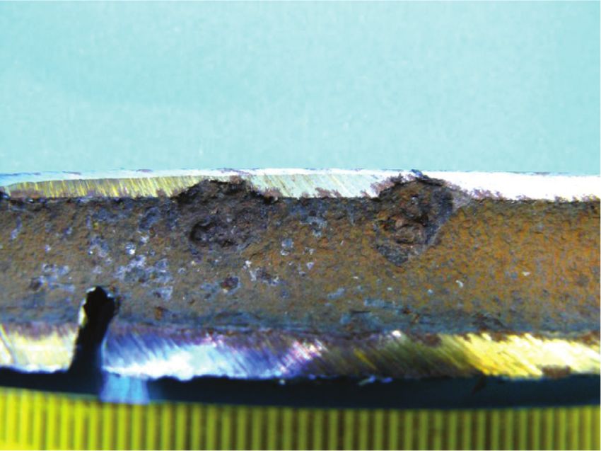
W. Faes et al.: Corrosion and corrosion prevention in heat exchangers 5
lower and upper tubes were preferentially filled with brine similarity to pitting corrosion and will be discussed in the
and steam, respectively, while the middle tubes received next section.
a mixture of condensing steam and brine. These condi-
tions caused an increasing concentration of acid gases
like CO2 and H2S in the condensing water, making it even 2.3 Crevice corrosion
more acidic. This locally high acidity was suggested as
the reason for the rapid development of pits in only one Crevice corrosion is another intense and dangerous form
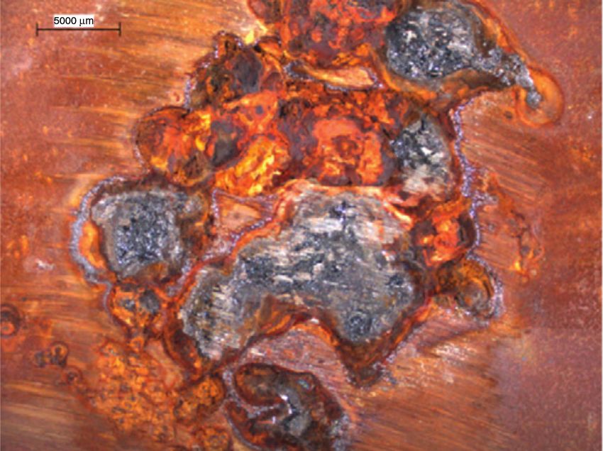
row of tubes. Also, elemental arsenic, which precipitated of localised corrosion, caused by a local environment dif-
from the brine, was observed in the pits, which might have ferent from the bulk environment. In crevices or shielded
enhanced corrosion by galvanic effects (galvanic corro- areas with stagnant liquid, a depletion of oxygen can
sion is discussed in Section 2.7). occur. The initiation of crevice corrosion is influenced by
An example of a plate heat exchanger that failed due this differential concentration of oxygen. The presence of
to pitting is described by Deen et al. (2010). In their study, chlorides can also cause the initiation of crevice corrosion.
the failure of a heat exchanger with plates constructed The rate of corrosion increases as the crevice narrows and
with type 316L stainless-steel plates (PREN ≈ 24.2) is the cathode area is increased (Roberge, 2000). In plate
investigated. The device was used in the cooling loop of heat exchangers, such crevices are typically present at the
textile mill. A 316L stainless steel was originally chosen gaskets (metal/non-metal contact), at the plate contact
for its corrosion-resistant properties; however, when the points, and under deposits.
heat exchanger was opened for maintenance after 2000 h The studies by Crum et al. (2007) and Cassagne et al.
of operation, it was observed that several of the plates (2010) illustrate the difficulty of avoiding crevice corrosion
were perforated by pits. An example of a failed plate can in plate heat exchangers for seawater applications. In both
be seen in Figure 6. The authors concluded that a local studies, several metals are tested as plate material at ele-
breakdown of the passive oxide film occurred, which was vated temperatures (up to 70°C) with both laboratory tests
caused by high chloride contents in the cooling water. and exposure to real seawater (with controlled chlorine
Additional examples of failure analyses of shell-and- concentrations, added to suppress marine life) in dummy
tube heat exchangers where pitting was one of the main heat exchangers. The metals tested were super-austenitic
modes of corrosion-related failure can be found in the fol- stainless steels, nickel-chromium-molybdenum alloys, and
lowing references: Xie et al. (2015), Ghayad et al. (2015), titanium. Almost all metals, even titanium, showed signs
Qiankun et al. (2017), Sanders and Iwand (2013), Ifezue of crevice corrosion in the most severe conditions. Only the
and Tobins (2015), Zheng et al. (2014), Song et al. (2013), most recent Ni-Cr-Mo alloys, like alloy 686 [Unified Num-
and Abouswa et al. (2007). Two papers in which pitting bering System (UNS) N06686], could withstand the corro-
corrosion in plate heat exchangers was observed are sive environment. An example of severe crevice corrosion at
described by Crum et al. (2007) and Turissini et al. (1997). the gasket area of a plate made from alloy 31 (UNS N08031)
The main corrosion process in this last case was, however, is shown in Figure 7. More cases of crevice corrosion in plate
crevice corrosion, which is a type of corrosion with some heat exchangers were described by Turissini et al. (1997).
Figure 6: Pitting corrosion damage in a plate heat exchanger.
Reprinted from Deen et al. (2010), with permission from Elsevier.
Authenticated | willem.faes@ugent.be author's copy
Download Date | 3/14/19 10:31 AM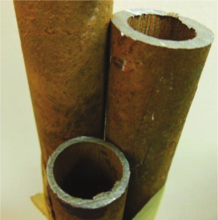
6        W. Faes et al.: Corrosion and corrosion prevention in heat exchangers

                                                                      external, but also residual stresses, e.g. from welding
                                                                      or cold working (Roberge, 2000). In shell-and-tube heat
                                                                      exchangers, residual stresses are often found at tube-to-
                                                                      tube sheet expanded joints and U-bends (Kuppan, 2000).
                                                                      Residual stresses also often cause SCC in cold-rolled plate
                                                                      heat exchangers (Wang et al., 2007).
                                                                           Walker (1990) mentioned that SCC can also be caused
                                                                      by corrosion products in a constricted or confined space.
                                                                      The volume of corrosion products is often larger than that
                                                                      of the base metal, causing a wedging action with high
                                                                      local stresses. Similar to this wedging is denting, which
                                                                      occurred in nuclear steam generators (Walker, 1990).
                                                                      Inconel tubes passed through carbon steel supports that
                                                                      corroded. The tubes were dented inwards because of
                                                                      an accumulation of corrosion products in the annulus
                                                                      between the tubes and the support.
                                                                           A second kind of corrosion where stresses play a role
Figure 7: Crevice corrosion under the gasket of a plate heat          is corrosion fatigue. This is characterised by a fluctuat-
exchanger.                                                            ing load substantially below the yield point. The fatigue
Reprinted with permission from NACE International, from Cassagne
                                                                      behaviour of metals is affected by corrosive media. Figure 8
et al. (2010).
                                                                      illustrates the influence of corrosion on the fatigue behav-
                                                                      iour with an S-N curve. It can be seen that failure occurs
     In shell-and-tube heat exchangers, the critical areas            within fewer cycles for a given stress, and a fatigue limit
for crevice corrosion are clearances between rolled                   is no longer observed (Revie & Uhlig, 2008). Similar to
tubes and tube sheets, open welds, and bolt holes. Also,              SCC, corrosion fatigue is often initiated at various types of
complex geometric designs with sharp edges are prone to               stress concentrations (Wang et al., 2007).
crevice corrosion (Kuppan, 2000). The investigations in                    Tawancy (2009) analysed the failure of a shell-and-
the publications by Yang et al. (2012), Kaul et al. (1995),           tube heat exchanger used in an oil refinery. Leaks were
and Allahkaram et al. (2011) give some additional exam-               detected in some bends after 48 h of starting the unit after
ples of failure analyses where crevice corrosion was                  a period of downtime. The conclusion of the author is that
found between the tube and the tube sheet. In the work                during the shutdown, polythionic acid was formed from
of Allahkaram et al. (2011), crevice corrosion was also               sulphur-bearing deposits and condensed water vapour.
found in gaps between the tubes and the baffles. A last               This acid, in combination with internal stresses in the
example is the study on oil coolers by Eich (2012) (already           bend, induced the cracks in the metal (type 321 steel),
mentioned in the discussion of uniform corrosion), where              shown in the photograph of Figure 9.
crevice corrosion was detected on the tube sheet. The
crevice was, however, not formed between the tube sheet
and the tubes but between the tube sheet and a deflector
in the head of the cooler.

2.4 Stress corrosion

When a corrosive environment is combined with mechan-
ical stresses, the corrosion process is aggravated. A first
type where corrosion and stress join forces is stress cor-
rosion cracking (SCC). This corrosion mechanism involves
a static tensile stress present in a susceptible metal in a
corrosive environment, causing failure where the same
structure would be able to endure the same stress in                  Figure 8: S-N curve illustrating the influence of corrosion on fatigue
a non-corrosive environment. These stresses can be                    behaviour.

                                                                                 Authenticated | willem.faes@ugent.be author's copy
                                                                                                  Download Date | 3/14/19 10:31 AM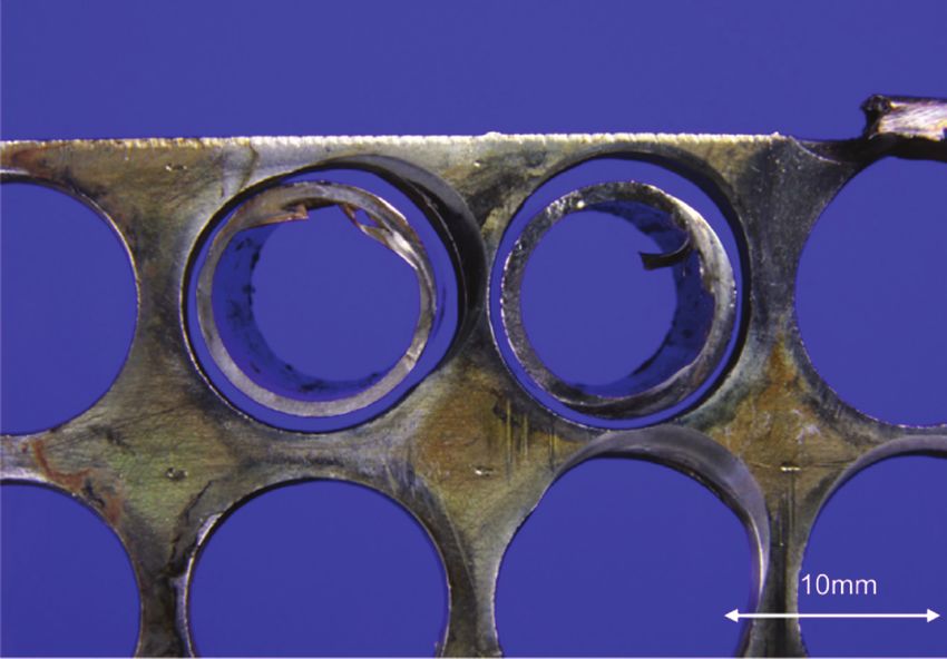
W. Faes et al.: Corrosion and corrosion prevention in heat exchangers          7

Figure 9: Stress corrosion cracks induced in a bend by polythionic
acid.
Reprinted from Tawancy (2009), with permission from Elsevier.

     Several other examples of stress corrosion causing the            Figure 10: Effect of flow velocity on the corrosion rate of carbon
failure of heat exchangers can be found in the literature              steel in seawater.
for both shell-and-tube heat exchangers (Otegui & Fazzini,
2004; Guo et al., 2011; Qu et al., 2011; Ravindranath et al.,
                                                                       prone to erosion corrosion, especially at the tube side,
2012; El-Amoush et al., 2014; Corte et al., 2015; Xu et al.,
                                                                       where this is often called inlet-tube corrosion (Walker,
2015; Corleto & Argade, 2017) and plate heat exchangers
                                                                       1990).
(Turissini et al., 1997; Traubert & Jur, 2012; Khodamorad
                                                                            Two other forms of wear, sometimes classified under
et al., 2016). For two of these cases, it concerns corrosion
                                                                       erosion corrosion, are “cavitation erosion” and “fret-
fatigue (Otegui & Fazzini, 2004; Ravindranath et al., 2012),
                                                                       ting corrosion” (Walker, 1990). On the one hand, in the
while in the others, SCC was the main cause of failure.
                                                                       former, bubbles collapse on the surface. This often occurs
                                                                       in evaporators, but is also possible in non-boiling condi-
                                                                       tions at pressure drops, resulting from sudden changes in
2.5 Erosion corrosion                                                 velocity. Fretting corrosion, on the other hand, is caused
                                                                       by a periodic rubbing motion between two metal parts.
Erosion corrosion is the synergistic interaction between               This often occurs in shell-and-tube heat exchangers at the
corrosion and erosion, caused by a relative motion between             tube-to-tube sheet joints or at the tube-baffle contacts.
a corrosive fluid and a metal wall. The combined effect of             This increases the shell-side baffle bypass flow, leading to
the two phenomena is larger than corrosion or erosion                  a less efficient heat exchanger.
separately. The phenomenon normally occurs under tur-                       Several examples of erosion corrosion can be found in
bulent flow conditions. Surface material is removed by                 the literature for shell-and-tube heat exchangers. Erosion
the fluid shear stress, and a protective corrosion film (e.g.          corrosion was observed in several studies (Kuznicka,
formed on stainless steel or aluminium) can be destroyed               2009; Eich, 2012; Yang et al., 2012; Li et al., 2013; Klein
by the motion of the fluid. The damage increases with                  et al., 2014). Also, some examples of cavitation erosion
increasing fluid velocity, and most metals have a criti-               (Reitz, 2002; Klenowicz et al., 2003) and fretting corrosion
cal velocity above which the corrosion rate strongly rises             (Cassagne et al., 2010; Klein et al., 2014; Shahrani & Al-
due to the destruction of the protective film (Wang et al.,            Subai, 2014) could be found. An example of a plate heat
2007). In seawater, where there is a high chloride con-                exchanger that failed because of fretting corrosion was
centration, stainless steel might not be able to establish             described by Wassilkowska et al. (2016).
passivity, causing the corrosion rate to increase with flow                 In the case described by Kuznicka (2009), pits were
velocity (Revie & Uhlig, 2008). A relationship between the             detected on the outside surface of the copper tubes in a
flow velocity of seawater and the corrosion rate of carbon             shell-and-tube heat exchanger. Some of these pits were
steel was proposed by LaQue (1948). This relationship was              perforating the tube wall. Around the tubes, industrial
fitted to an exponential function by Guedes-Soares et al.              water was flowing with an inlet temperature of 16°C. The
(2011), as shown in Figure 10.                                         inside surface of the pits was smooth and free of corrosion
     In plate heat exchangers, erosion corrosion can occur             products. The pits were positioned in the longitudinal
at the inlets and is more severe when the fluid contains               direction of the tube and appeared as craters undercutting
abrasive solids such as sand particles (Wang et al., 2007).            the metal. These observations led the author to believe
In shell-and-tube heat exchangers, the inlets are also                 that the pits were created by erosion corrosion. Also, the

                                                                                  Authenticated | willem.faes@ugent.be author's copy
                                                                                                   Download Date | 3/14/19 10:31 AM
8         W. Faes et al.: Corrosion and corrosion prevention in heat exchangers

fact that the water contained some solids in suspension                2.6 Intergranular corrosion
was thought to be the possible cause of the erosion corro-
sion. Most of the tubes on which the pits were discovered              In solid state, metals typically have a crystalline structure.
were laying in the same row: the row closest to the baffle             Carbon steel has a body-centred cubic crystal structure;
edge. According to the author, the turbulence was most                 aluminium, copper, and austenitic stainless steel are
intense at this location, increasing the effect of erosion             face-centred cubic; and magnesium has hexagonal close-
corrosion.                                                             packed crystal lattice. During the solidification process,
     An example of a shell-and-tube heat exchanger that                these crystals are formed as individual grains where the
failed because of fretting corrosion is discussed by Klein             boundaries between the different grains are chemically
et al. (2014). In a wastewater plant, hot vapours were used            more active (Walker, 1990).
on the shell side. These vapours, however, contained                        Narrow regions along the grain boundaries can be
some debris, fouling the outer surface of the tubes. This              corroded with only negligible attack on the grains them-
blocked the flow path in some areas of the heat exchanger,             selves. This can cause the metal to disintegrate or lose
causing the fluid velocity to be higher in other regions. An           its strength. Intergranular corrosion often occurs on
oscillating behaviour of the tubes resulting from these                welded structures of the widely used type 304 stainless
high velocities caused the tubes to be in contact with each            steel. Operation at high temperatures, like an improper
other, inducing fretting corrosion on each other. Figures 11           heat treatment or welding, can cause the depletion of
and 12, respectively, show friction marks on the outside of            the alloying element chromium near the grain bounda-
the tubes and worn-out holes in the baffle plates, created             ries in a process called sensitisation. These chromium-
by the vibrating motion of the tubes.                                  depleted regions have lost their corrosion resistance,
     Only one case of erosion corrosion (in the form of fret-          and what remains are the characteristics of the base
ting corrosion) could be found for plate heat exchangers.              metal (Kuppan, 2000). The chromium forms chromium
The corrosion process was described by Cassagne et al.                 carbides, because at these temperatures, the carbides
(2010), who investigated materials for plate heat exchang-             are insoluble and for them to precipitate at the grain
ers. The fretting corrosion occurred at the contact points             boundaries, they must obtain chromium from the sur-
of adjacent plates.                                                    rounding metal. When the corroding metal is under a
                                                                       tensile stress, corrosion cracks can form along the grain
                                                                       boundaries. This phenomenon is termed intergranular
                                                                       SCC (Roberge, 2000).
                                                                            From the examples given in the section on stress
                                                                       corrosion, the cracks discussed in several publications
                                                                       were intergranular (Turissini et al., 1997; Guo et al., 2011;
                                                                       Corleto & Argade, 2017). Intergranular cracks (without the
Figure 11: Friction marks on the outside of heat exchanger tubes.
Reprinted from Klein et al. (2014), with permission from Elsevier.     application of stresses) were found in the cases discussed
                                                                       by Ifezue and Tobins (2015) (together with pitting) and
                                                                       Chandra et al. (2010). Figure 13, from the work of Ifezue
                                                                       and Tobins (2015), clearly shows intergranular corrosion
                                                                       of a section of an aluminium tube, which typically results

                                                                       Figure 13: Intergranular corrosion of an aluminium tube.
Figure 12: Worn-out holes in a baffle plate.                           Reprinted by permission from Springer Nature: Journal of Failure
Reprinted from Klein et al. (2014), with permission from Elsevier.     Analysis and Prevention, Ifezue and Tobins (2015), Copyright 2015.

                                                                                  Authenticated | willem.faes@ugent.be author's copy
                                                                                                   Download Date | 3/14/19 10:31 AM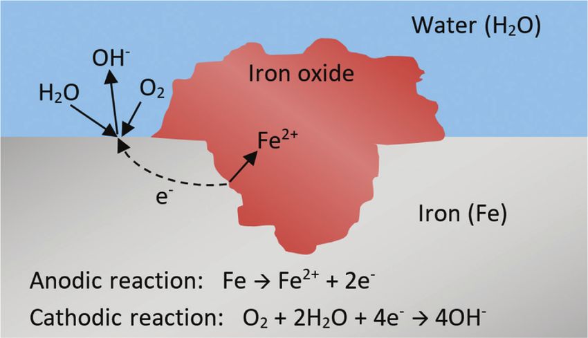
W. Faes et al.: Corrosion and corrosion prevention in heat exchangers     9

from inappropriate heat treatment, e.g. during material          2.8 Selective leaching
production.
                                                                 Selective leaching or de-alloying is a form of galvanic cor-
                                                                 rosion on a microscopic scale where one alloying element
2.7 Galvanic corrosion                                          is preferentially attacked over the other alloying elements
                                                                 in the matrix material. As a result, the remaining structure
When two dissimilar metals are electrically connected and        is weakened (Roberge, 2000). A common example is the
are in contact with an electrolyte, a galvanic cell is created   removal of zinc from brass (de-zincification) in stagnant
and a potential difference exists over the two metals. In        waters. Also, the removal of aluminium from aluminium
this bimetallic couple, the metal with the lowest poten-         brass in acidic solutions or nickel from cupronickel alloys
tial, the anode, will start to corrode. The more noble metal     under conditions of high heat flux (respectively called de-
will behave as a cathode, and its surface will remain unaf-      aluminiumification and de-nickelification) is reported in
fected (Roberge, 2000). In this context, it must be added        industry (Kuppan, 2000). Addition of appropriate alloy-
that the potential of a metal depends on the characteris-        ing elements is frequently quoted to be a viable strategy
tics of the electrolyte as well. Consequently, it is possible    against selective leaching. For example, de-zincification
that for two dissimilar metals, one metal is anodic with         of brass can be prevented in most aggressive environ-
respect to the other in one electrolyte, while it behaves        ments by adding arsenic as alloying element to the brass
cathodic with respect to the same other metal in a differ-       (Ravindranath et al., 2012).
ent electrolyte. Galvanic corrosion can also happen on a              According to Wang et al. (2007), failures caused by
single metal, caused by local imperfections, local differ-       selective leaching are not common in plate heat exchang-
ences in the chemistry of the electrolyte (e.g. an oxygen        ers, as they can be avoided by selecting an appropriate
concentration cell), or metallic deposits on the surface         material for each application. One example was found in
(Wang et al., 2007).                                             the literature where cupronickel tubes in a shell-and-tube
     Galvanic corrosion is common in shell-and-tube heat         heat exchanger experienced de-nickelification (Cincera
exchangers at the contacts between the tubes and the             et al., 2012). The failure analyses in publications by Qu
baffles or tube sheets when different metals are used for        et al. (2011), Ravindranath et al. (2012), Li et al. (2013), and
those parts. Also, the contacts between the baffle and           Ranjbar (2010) mention de-zincification as one of multiple
the shell are sensitive areas (Kuppan, 2000). In plate           causes of failure of a shell-and-tube heat exchanger.
heat exchangers, galvanic corrosion can exist at welded,              In the example discussed by Ranjbar (2010), tubes
brazed, or soldered joints (Wang et al., 2007). One spe-         made of yellow brass were used in a shell-and-tube heat
cific example of galvanic corrosion was already men-             exchanger. In the tubes, circulating cooling water flowed
tioned in Section 1. Parrott (2014) described the failure of     to condense the steam on the shell side. Several tubes
a shell-and-tube heat exchanger made from carbon steel           experienced severe fouling and even plugging, causing
with a titanium cladding on an offshore gas production           the velocity to increase in the tubes that were not plugged.
platform. In this case, the carbon steel was anodic to the       The flow in these tubes was rapid with a high turbulence
titanium and corroded. Another example of galvanic cor-          intensity. Additionally, the metal was weakened, because
rosion where carbon steel was anodic to titanium was             zinc was leached from the copper alloy. This weaken-
discussed by Yang et al. (2012) in a failure analysis of a       ing, in combination with the turbulent motion, caused
shell-and-tube heat exchanger (caused by a combina-              severe erosion. A section that de-zincified can be seen in
tion of corrosion mechanisms) in a nuclear power plant.          Figure 14. The original brass had a yellow colour, while
One last illustration of the need to avoid combining dis-        the de-zincified area has a red colour, as one typically
similar metals is the failure analysis of Mousavian et al.       observes for pure copper.
(2011). In a shell-and-tube heat exchanger, used to cool
oil with cooling water, the tubes, tube sheet, and gaskets
were made of copper, carbon steel, and aluminium,                2.9 Hydrogen damage
respectively. After being used for only 4 months, the oil
and water mixed because both the gaskets and the tube            Hydrogen can cause damage of a metal in different ways.
sheets corroded. Galvanic corrosion was determined to be         Atomic hydrogen H (not the molecule H2) is the smallest
the main cause of failure. The concept of galvanic corro-        atom and is often able to diffuse in the metal lattice inter-
sion is rather well known, so the mistake to bring different     stitially at a measurable rate, along grain boundaries and
metals into contact with each other is only seldom made.         along dislocations. Dislocations often play a crucial role

                                                                            Authenticated | willem.faes@ugent.be author's copy
                                                                                             Download Date | 3/14/19 10:31 AM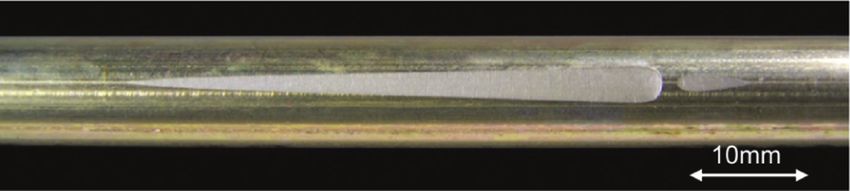
10          W. Faes et al.: Corrosion and corrosion prevention in heat exchangers

                                                                           steel with a stainless-steel cladding and used to heat
                                                                           naptha for the removal of sulphur, nitrogen, and oxygen
                                                                           impurities. The formation of cracks by HTHA occurred
                                                                           near the welds and was facilitated because the shell did
                                                                           not receive an appropriate post-weld heat treatment.

                                                                           2.10 Microbiologically induced corrosion

                                                                           Microbiologically induced corrosion (MIC) is described in
                                                                           a paper by Dexter (2003). Microorganisms, including bac-
                                                                           teria, algae, and fungi, are encountered not only in almost
Figure 14: De-zincification of the inner surface of a yellow brass tube.   every natural aqueous environment but also in several
Reprinted from Ranjbar (2010), with permission from Elsevier.              industrial fluids. They are, for example, very common in
                                                                           cooling water systems, where they reduce the heat trans-
                                                                           fer rates and increase the pressure drop over the con-
in hydrogen-related failure (Depover & Verbeken, 2018).                    denser (Rao & Nair, 1998). When these organisms attach to
Atomic hydrogen can be produced by the cathodic reac-                      a surface, a biofilm is formed that will influence corrosion.
tion of the corrosion process, while the formation of H2                   The microorganisms can initiate corrosion, which would
during the cathodic reaction can be caused by the pres-                    not occur in the same environment without microorgan-
ence of certain chemical species (so called “poisons”, like                isms. The biofilm can also change the type of corrosion
H2S) (Roberge, 2000).                                                      (e.g. from uniform to localised corrosion) or increase or
     A first form of corrosion damage caused by atomic                     decrease the corrosion rate. It is, however, also possible
hydrogen is hydrogen blistering. This is caused by atomic                  that the biofilm does not influence corrosion. The possi-
hydrogen collecting at internal defects, close to the                      ble influences of microorganisms on corrosion are sum-
sample surface. In these cavities, it recombines to gaseous                marised by Dexter (2003) and schematically represented
H2, building up very high internal pressures. This causes                  in Figure 15.
blisters to form on the metal surface. Another form of                          A failure analysis was done by Huttunen-Saarivirta
hydrogen damage is hydrogen-induced cracking (HIC),                        et al. (2012) on a stainless-steel (type 304) shell-and-tube
where the metal is embrittled by the present hydrogen.                     heat exchanger that was used for only 36 months. On the
When stressed, the normally ductile metal will fail with                   surface of the shell, where the cooling water flows, corro-
a significantly reduced elongation. This form of corrosion                 sion tubercles (Figure 16) were found. Some of them pen-
is called sulphide stress cracking when the environment                    etrated the metal (with an original thickness of 6.2 mm),
in which the HIC occurred contains H2S (Roberge, 2000).                    while most of them had a depth of 2–4 mm. The investi-
At elevated temperatures (>232°C) and high pressures (>7                   gation showed that the metal had both a major austenite
bar), molecular hydrogen can dissociate to atomic hydro-                   phase and a minor ferrite phase. There was a micro-scale
gen on steel surfaces and diffuse into the steel (Groysman,
2017). At grain boundaries, dislocations, and inclusions
(such as carbides) in the steel, it can form methane (CH4).
This process, called HTHA, decarburises the steel, reduc-
ing its mechanical properties.
     Titanium is susceptible to hydrogen damage due to
hydride formation, as illustrated by the paper by Yang
et al. (2012). In this study, the leakage of titanium tubes of
a heat exchanger in a nuclear power plant is investigated.
Some galvanic corrosion and crevice corrosion produced
hydrogen, leading to HIC.
     HTHA was indicated to be the cause of the catastrophic
failure and explosion of a heat exchanger in the refinery
plant mentioned in Section 1 (CSB, 2010; Marsh, 2016).
The shell-and-tube heat exchanger was made from carbon                     Figure 15: Influence of a biofilm on the corrosion rate.

                                                                                   Authenticated | willem.faes@ugent.be author's copy
                                                                                                    Download Date | 3/14/19 10:31 AM
W. Faes et al.: Corrosion and corrosion prevention in heat exchangers 11
T w,h T w,c
T b,h T b,c
Rconv,h Rcond Rconv,c
Figure 17: Thermal resistance network for heat transfer from a hot
to a cold fluid over a heat transfer surface.
This figure shows the bulk (Tb) and wall (Tw) temperature
on the hot (h) and the cold (c) sides, the two convective
resistances (Rconv), and the conductive resistance (Rcond).
The kinetics of electrochemical reactions (such as
corrosion of a metal surface) normally increase with
increasing temperature. An exponential relationship,
which is reflected in the Arrhenius equation, usually
Figure 16: Tubercles observed on the shell surface of a heat
exists between temperature and reaction rates (Silverman,
exchanger. 2003). This implies that when a corrosive fluid is heated,
Reprinted from Huttunen-Saarivirta et al. (2012), with permission the temperature in the boundary layer near the wall is
from Elsevier. higher and corrosion kinetics will be faster than kinetics
driven by the bulk temperature (Tw,c > Tb,c). However, when
a corrosive fluid is cooled, the metal temperature will be
surface roughness at this ferrite phase, giving bacteria the
lower than the bulk fluid temperature (Tw,h < Tb,h) and the
possibility of attachment, subsequently leading to oxygen
corrosion kinetics are reduced (Moore & Smith, 1967). A
concentration cells. These cells locally induced corrosion
schematic illustration of the temperature profile over the
and created the tubercles.
fluids, the boundary layers, and the surface is given in
In the literature, more examples can be found of
Figure 18.
heat exchangers that failed due to MIC (Rao & Nair, 1998;
The local differences in temperature also cause differ-
Abraham et al., 2009; Sharma, 2014; Rizk et al., 2017).
ent solubility products of substances in the fluid. For most
species, the solubility increases with increasing tempera-
ture, while some have inverted characteristics (Stumm &
3 Corrosion and heat transfer Morgan, 2012). Corrosion products are typically among
the first category. As explained, the temperature of the
In this section, the interaction between corrosion and bulk fluid in a heat exchanger is different than the metal
heat transfer is discussed. The first part explains how a temperature or the temperature of the fluid in a boundary
metal surface can experience differences in the corrosion layer near the wall. Heat transfer to the liquid can cause
process under heat transfer conditions, compared to when the corrosion products to dissolve instead of forming a
the temperature distribution is uniform. In the second protective layer, because their solubility near the wall is
part, it is demonstrated how corrosion can affect heat high. This can increase the corrosion rate. When a liquid
transfer and the performance of a heat exchanger.
3.1 I nfluence of heat transfer on corrosion
When heat is transferred from a solid wall to a fluid (or
vice versa), a temperature gradient exists, causing the
fluid near the surface to have a different temperature
than the bulk fluid (Welty et al., 2009). The temperature
of the boundary layers near the wall depends on the tem-
peratures of the bulk fluid, the conductive thermal resist-
ance of the heat transfer surface, and the relative value
of the convection coefficients. This can be illustrated with Figure 18: Temperature profile when a corrosive fluid is being
a thermal resistance network, as illustrated in Figure 17. cooled (left) and heated (right).
Authenticated | willem.faes@ugent.be author's copy
Download Date | 3/14/19 10:31 AM12 W. Faes et al.: Corrosion and corrosion prevention in heat exchangers
is cooled, the corrosion products do not have the tendency then occurs at the point where the solution reaches a criti-
to dissolve, but form an adherent scale, protecting the cal concentration.
surface from further corrosion (Ross, 1967). In addition to
the corrosion products, the corrosive species causing the
degradation of the metal also experience this change in 3.2 Influence of corrosion on heat transfer
solubility. Dissolved oxygen, for example, has an inverted
solubility characteristic, so it is less soluble at higher tem- Not only does heat transfer have an influence on the cor-
peratures. The mass transport of oxygen from the bulk rosion process, but corrosion can also negatively affect
fluid to the hotter metal is difficult, so this might counter- the thermohydraulic performance of the heat exchanger
act the higher corrosion rates expected for a heated fluid (Edwards, 2008; Mousavian et al., 2011).
(Ross, 1967). This is illustrated by the study of Zhao et al. (2012),
Not only a temperature gradient between the fluid in where the effect of corrosion on the performance of fin-
the boundary layer and the bulk fluid can affect corrosion. and-tube heat exchangers was investigated. The heat
On the heat transfer surface itself, different areas can have exchangers were subject to accelerated corrosion by
another temperature. According to Roberge (2000), hot keeping them in a standardised salt spray chamber for 48
metal is anodic to the same metal at a lower temperature. or 96 h. The performance after being corroded was evalu-
This is a cause of thermogalvanic corrosion, which was ated based on the cooling capacity, the heat transfer coef-
mentioned by Ross (1967), Green (1967), and Maylor (1967). ficient, the thermal resistance, and the air-side pressure
Ross (1967) and Green (1967) indicated this phenomenon drop, and compared to the performance before the test.
with the term “hot-spot corrosion”. In heat exchang- All heat exchangers had copper tubes, while the fins were
ers, local overheating typically occurs under deposits or either copper or aluminium. The influence on the cooling
because of damaging behaviour of the flow, like e.g. the capacity can be seen in Figure 19. The cooling capacity
impingement of steam, an acceleration at blockages, or of the heat exchangers with the copper fins is highest for
the stagnation in enlargements. This hot-spot corrosion is all flow rates, both before and after corrosion, due to the
discussed in more detail by Francis (1987). According to higher conductivity of copper than aluminium. The reduc-
this author, it is common in copper alloy heat exchanger tion in performance after the corrosion is larger for the
tubes, and its process depends on the temperatures and samples with the aluminium fins (maximally 19%) than
the chemicals in the water. Several examples can be for the samples with the copper fins (maximally 2%).
found of hot-spot corrosion in copper tubes in desalina- In the study by Zhao et al. (2012), the decrease in
tion plants (Todd, 1967; Powell & Michels, 2000; Abouswa heat transfer is attributed to a layer of corrosion prod-
et al., 2007). ucts that formed on the fins (mainly Al2O3, aggravated by
Additional complications occur during a change of
phase of the fluid. When a liquid starts boiling, small
bubbles of vapour are produced on the surface (nucleate Sample with Cu fins #1 #2 #3
Sample with Al fins
boiling). These bubbles can collapse and cause cavita- 6000 #1 #2 #3
tion erosion of the surface, possibly removing a protective
#1 #2 #3
layer (Green, 1967; Ross, 1967). 5000
Cooling capacity (W)
During the condensing of a vapour, a layer of liquid #1 #2 #3
4000
forms on the metal. Gases in the vapour may dissolve in
the condensate, causing localised corrosion on the metal 3000
surface (Moore & Smith, 1967; Ross, 1967). This process is
sometimes called condensate corrosion (Boffardi, 2003) 2000
and is the cause of the failure of the heat exchanger dis- 1000
cussed by Julian et al. (2015), described in the part about
pitting corrosion. 0
300 400 550 720
A last type of corrosion induced by heat transfer is Air flow rate (m3/h)
“liquid-line corrosion”, described by Green (1967). When #1 before salt spray test, #2 after 48 hours salt spray test,
a diluted acid, flowing through a tube, is heated, the water #3 after 96 hours salt spray test
can evaporate. A more concentrated solution is remaining, Figure 19: Influence of corrosion on the cooling capacity of a fin-
which might be corrosive to the metal, although the origi- and-tube heat exchanger.
nal diluted acid was not a problem. Localised corrosion Reprinted from Zhao et al. (2012), with permission from Elsevier.
Authenticated | willem.faes@ugent.be author's copy
Download Date | 3/14/19 10:31 AMW. Faes et al.: Corrosion and corrosion prevention in heat exchangers 13
Table 1: Thermal conductivity of various metals and metal oxides.
Metal Thermal conductivity Oxide Thermal conductivity
(W m–1 K–1) (W m–1 K–1)
Aluminium 237 (Kakaç et al., 2012) Aluminium oxide (Al2O3) 25 (Weast, 1981)–40 (Kakaç et al., 2012)
Copper 401 (Kakaç et al., 2012) Copper(II) oxide (CuO) 20 (Kakaç et al., 2012)
Carbon steel 52 (Weast, 1981) Iron oxide 0.58 (The Engineering ToolBox, 2017)
Stainless steel 17 (Weast, 1981) Chromium(III) oxide (Cr2O3) 10–33 (Shackelford & Alexander, 2001)
Titanium 20 (Weast, 1981) Titanium dioxide (TiO2) 11.7 (AZoM)
the galvanic cell that exists between the aluminium fins successfully been used to reduce weight and improve
and the copper tubes). This additional thermal resistance corrosion resistance in heat exchangers (Knezevic et al.,
caused by corrosion products also occurs in other heat 2014). When using different metals, one should, however,
exchangers constructed from different materials (Turissini be careful to avoid galvanic corrosion (see Section 2.7),
et al., 1997; Ranjbar, 2010; Yang et al., 2012). Table 1 lists not only with bimetallic tubes but also for tube and tube
the thermal conductivity of some metals commonly used sheet combinations or with smaller elements like bolts
in the construction of heat exchangers and some of the (Kuppan, 2000). When the use of two different metals
oxides that typically result from corrosion of these metals. cannot be avoided, they should be electrically insulated.
It can be seen that the thermal conductivity of the corro- The anodic (corroding) part should be readily replaceable
sion products is often significantly lower than that of the and have a larger surface than the cathode (area effect)
base metal. This could be expected as oxides are ceramics, (Walker, 1990). To protect the metal from the aggressive
which usually are thermal insulators because of their lack environment, coatings can be applied on the surface. Coat-
of large numbers of free electrons (Callister & Rethwisch, ings generally do not provide any mechanical strength,
2011). but only isolate the material from the fluid to preserve its
strength and integrity (Roberge, 2000). They are typically
classified into three groups: metallic, organic, and inor-
4 P
revention of corrosion ganic (non-metallic) coatings.
–– Metallic coatings can be applied to a substrate in
several ways, for example hot dipping, electroplat-
4.1 G
eneral considerations and guidelines ing, spraying, cementation, and diffusion (Revie &
Uhlig, 2008). The choice of the type of coating process
Many problems with heat exchangers for corrosive appli- depends on several factors such as the required corro-
cations can be avoided by using good practice in the mate- sion resistance or the anticipated lifetime of the coat-
rial selection, during the design phase, and during the ing. Nickel, zinc (e.g. galvanising of steel), lead, tin,
operation of the device. aluminium, cadmium, and chromium are some exam-
Material selection is one of the most important ples of metals that are often applied as coating on a
aspects in avoiding corrosion of a heat exchanger in a spe- substrate made of another material (Carter, 1977). The
cific fluid. Some metals are better suited for a certain envi- coating can be both cathodic or anodic with respect to
ronment than others, and the most appropriate material the substrate.
should be chosen (Tuthill, 1990). If only expensive, highly –– Paints, resins, lacquers, varnishes, and plastic lin-
alloyed materials can resist the environment, a plate heat ings are all categorised as organic coatings (Roberge,
exchanger is preferred, because these require less mate- 2008). They are typically designed to have a high
rial than a shell-and-tube heat exchanger. If, however, a impermeability and an inhibitive function to the cor-
shell-and-tube heat exchanger would be preferred, the rosion process while they can also contain cathodi-
corrosive fluid has to flow in the tubes, as then the shell cally protective pigments.
can be made of a cheaper metal (Kakaç et al., 2012). For –– Inorganic (non-metallic) coatings can be divided into
shell-and-tube heat exchangers with different corrosive two categories (Roberge, 2008). Hydraulic cements,
fluids on the shell side and the tube side, bimetallic tubes ceramics, carbon, silicates, and glass are applied on
are sometimes used. These tubes are made from two dif- the surface of the protected substrate. Other treat-
ferent metals, which are usually co-extruded and have ments change the natural characteristics of the oxide
Authenticated | willem.faes@ugent.be author's copy
Download Date | 3/14/19 10:31 AM14 W. Faes et al.: Corrosion and corrosion prevention in heat exchangers
film, with a low corrosion resistance, into a different the holes in the tube sheets before rolling should be as
protective film or metallic oxide with a higher cor- small as possible. Otherwise, residual stresses after rolling
rosion resistance in the specific operational envi- could induce SCC (Kuppan, 2000). To completely rule out
ronment. Some examples here include anodising, leakages from one fluid to the other, special designs with
nitriding, and phosphatising. double tube sheets in shell-and-tube heat exchangers or
double-wall plates in plate heat exchangers can be used
Each of these types of coatings has been applied in heat (Kuppan, 2000). With these designs, any leakage at the
exchangers to protect the heat transfer surface from a cor- tube-tube sheet interface or through a pit in a plate will be
rosive environment (Chang & You, 1997; Fedrizzi et al., to the environment instead of to the other fluid.
2008; Jong-Soon et al., 2009). In addition to the protec- Special care should also be taken when designing the
tion from corrosion, coatings can also fulfil a different flow path. Dead spaces or areas with low velocities have
role. Wang and Chang (1998) tested hydrophilic coatings to be avoided, because they can induce pitting or crevice
to improve the condensate draining in fin-and-tube heat corrosion. Dead spaces can, for example, exist in verti-
exchangers. This better draining could reduce the pres- cal shell-and-tube heat exchangers above the upper tube
sure drop up to 40%. Also in dehumidifying heat exchang- sheet as a result of a wrong rolling procedure where the
ers, hydrophilic coatings have successfully been applied tubes protrude the tube sheet and a crown is produced
(Hong & Webb, 2000). Hydrophobic coatings, however, in the tube sheet (Collins, 1955). An incorrectly and a cor-
have also been tested in heat exchangers. Das et al. (2000) rectly rolled tube bundle are shown in Figure 20. The fluid
applied such coatings on copper tubes to promote drop- velocity should also not be too high, as this can cause
wise condensation in a condenser. The achieved heat erosion corrosion. Erosion corrosion at the first centime-
transfer coefficients were, in some cases, 14 times higher tres of the tubes is common and often called tube-inlet
than with filmwise condensation. A disadvantage of coat- corrosion. It can be prevented by inserting a short, wear-
ings is that they usually have a significantly lower thermal resistant tube in the wearing inlets, similar to the princi-
conductivity – lower than that of the base metal. In gas ple of bimetallic tubing (Kuppan, 2000). The outer surface
turbines, for example, inorganic coatings are applied of the tubes located near the inlet of the shell is also sen-
because of their lower thermal conductivity to reduce sitive to erosion corrosion. Protection can be provided
the temperature of the airfoils (Strangman, 1985). In heat under the form of wear-resistant impingement plates or
exchangers, their thickness is normally only in the order angle tube protectors, shown in Figures 21 and 22, respec-
of micrometres (Roberge, 2000), so their effect on the heat tively (Kuppan, 2000). Another type of corrosion that can
transfer is limited. be avoided by carefully designing the flow path is fretting
Apart from the material selection, some other meas- corrosion caused by flow-induced vibrations of the tubes.
ures can be taken during the design phase to reduce the Kuppan (2000) proposed changing the fluid velocity or
risk of corrosion-based failures. When the conditions stiffening the tubes with tube support plates, while Walker
to which the heat exchanger will be exposed can cause (1990) also mentioned the use of coatings to roughen the
uniform corrosion, the construction material is typically surface and dampen vibrations.
made thicker than required to guarantee the necessary Pakhomov and Parshin (1993) gave some recommen-
strength over the entire lifetime. This extra material is dations for the thermal design. They defined the term
called the corrosion allowance. This strategy is, however,
not possible with plate heat exchangers, because the plates
need to be very thin, both to maintain a compact form and
for production purposes (Kakaç et al., 2012). Also during
the design phase, sharp edges should be avoided, because
these can induce corrosion fatigue or crevice corrosion. In
general, crevices should always be avoided. When they
cannot be avoided, they should either be filled or be wide
and shallow. The connection between the tubes and the
tube sheets in shell-and-tube heat exchangers is a sensi-
tive location for crevice corrosion. One possibility to avoid
these crevices is to weld the connection instead of rolling.
When using a rolled connection, the difference between Figure 20: Dead space in a vertical heat exchanger (left) and a
the outer diameter of the tubes and the inner diameter of correctly rolled heat exchanger (right).
Authenticated | willem.faes@ugent.be author's copy
Download Date | 3/14/19 10:31 AMYou can also read