EVALUATION OF NON-ISOTHERMAL AIR JET PARAMETERS FROM RECORDS OF FLOW VISUALIZATION USING INTERFEROMETRY - VENTILATION 2006, May 13-18 in Chicago ...
←
→
Page content transcription
If your browser does not render page correctly, please read the page content below
VENTILATION 2006, May 13-18 in Chicago, Illinois

  EVALUATION OF NON-ISOTHERMAL
       AIR JET PARAMETERS
FROM RECORDS OF FLOW VISUALIZATION
      USING INTERFEROMETRY

          Milan PAVELEK - Eva JANOTKOVA
    Brno University of Technology – Czech Republic

                                                     1
INTRODUCTION
● Interferometry is a progressive
  visualization method for researching
  non-homogeneities in fluids.
● The non-homogeneities of air
  jets from outlets are due mainly
  to temperature. For this reason,     Candle
                                        flame
  it is only possible to investigate
  non-isothermal jets.
● Ordinary interferometers have a relatively narrow field of view,
  thereby enabling the observation of jets from small outlets used in
  cars, airplanes etc.

● Interferometers are frequently used for measurements of 2D or
  axially symmetrical temperature fields. This contribution, however, is
  aimed at jets, which are often 3D, and from whose interferograms it is
  also possible to derive interesting information.
                                                                       2
EXPERIMENTAL EQUIPMENT
A schematic diagram for the experimental setup used to measure the
initial parameters of jets from ventilation outlets and for measuring the
ambient air state is shown in this figure.

       Ventilator     Heat           Flowmeter          Interferometer
                    exchanger                            field of view
                                     VF
                                             Outlet                          y
                                                                                 x
                                                           w0
                          pF    TF             Ti     T0                 z
                                                                   pi

       Manometer                          Thermometer       Barometer

Ti [K]       ambient air temperature           VF [m3.s-1] is the volumetric
pi [Pa]      barometric pressure               flow for temperature TF [K]
To [K]       initial air temperature           and pressure pF [Pa]
wo [m.s-1]   initial air velocity                                                3
NON-ISOTHERMAL AIR JETS
The research is aimed at:
• strongly non-isothermal jets (Aro > 0.01)
• slightly non-isothermal jets (Aro ≤ 0.001)
Archimedes number is given by the Eq. (1)                do

      g(To − Ti )Lo
Aro =                            (1)
         w o2Ti                                Circular outlet, Ti = 295 K
                                                wo= 14 m.s-1, To= 338 K
g [m.s-2] acceleration due to gravity
Lo [m]    dimension of the outlet
          (diameter do of circular outlets,
          width bo of slot outlets etc.)
                                                         bo
Remark:
To investigate parameters of isothermal
jets, slightly non-isothermal jets must be
generated which have many parameters            Slot outlet, Ti = 296 K
in common with isothermal air jets.            wo= 1.7 m.s-1, To= 323 K
                                                                             4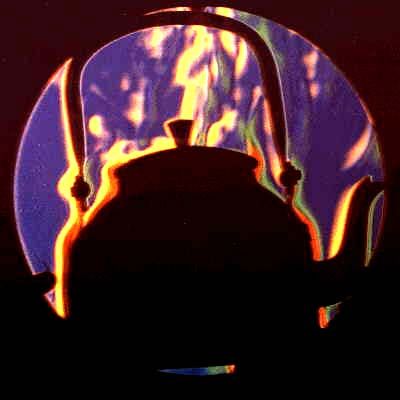
MACH - ZEHNDER INTERFEROMETER
For visualization and
measurement of 2D                                          MZI
                                     Model

                                             φ 200
temperature fields in
non-isothermal air jets,
a Mach - Zehnder
interferometer (MZI)
was chosen.
                             Mach-Zehnder
                             interferometer
  Model      Field of
 of outlet    view         The size of the interferometer field of
                           view (200 mm) limits the size of object
                           investigated, therefore scale models
    w0                     are needed to investigate larger
    to                     objects.
                           Similarity theory is then applied to the
                           measurement results.
                                                                   5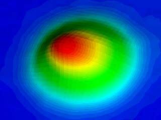
INTERFEROGRAM EVALUATION
The interferograms are processed and evaluated by our Interfer-Visual
software [1]. This software automatically evaluates:
• The course of
  interference
  fringes in images
• Fringe distribution
  in selected image
  sections … etc.
Evaluated data may be edited
interactively and transferred
to another program.
The focus is above all on
evaluating:
• Temperatures in jets
• Enthalpy in jets
• Jet boundaries and shapes
                                                                        6
LOCAL TEMPERATURES
The distribution of local temperatures in axial-symmetric or 2D non-
isothermal air jets can be obtained using an ordinary Mach - Zehnder
interferometer.
• Axial-symmetric
temperature fields
in the vicinity of circular
outlets (see figure) are
evaluated via our own
equations [2].
• 2D temperature fields
in the vicinity of slot or
rectangular outlets are
evaluated in our work
Temperature profiles in an air jet from
using equations from a circular outlet, do = 30 mm,
Hauf, Grigull [3]. x = 30 mm - core area of the jet
7ENTHALPY IN JETS
In lightly non-isothermal jets heat flow and
y x = const.
thereby enthalpy flow in direction x will be
constant, and will be equal to the heat
power of the outlet Wo [W]
Wo = w o ⋅ Ao ⋅ ρo ⋅ c p (To − Ti ) = (2) 0 x
= w(x) ⋅ A(x) ⋅ ρ(x) ⋅ c p [T(x) − Ti ]
A [m2] cross-section of flow
ρ [kg.m-3] mean flow density Rectangular outlet
cp [J.kg-1.K-1] specific heat (p = const.) Sides 3:1, Ti = 291 K
wo=18 m.s-1, To= 326 K
Equation (2) can be modified as follows:
Wo = w(x) ⋅ A(x) ⋅ ρ(x) ⋅ ∆h(x) = w(x) ⋅ A(x) ⋅ ∆hv (x) = w(x) ⋅ ∆hx (x) (3)
∆h(x) [J.kg-1] mean specific enthalpy in the cross-section x
∆hv(x) [J.m-3] mean volumetric enthalpy density in the cross-section x
∆hx(x) [J.m-1] mean linear enthalpy density in the cross-section x
8ENTHALPY IN 3D JETS
The change in mean linear enthalpy density
in the cross-section x can be obtained x = const.
effectively from interferometric records of y2
non-isothermal air jets [4], see equation (4)
y 2 (x)
c p ⋅Ti
∆hx (x) = − λ
K ∫ ∆S(x, y) dy
y 1 (x)
(4) y1
λ [m] wavelength of light Circular outlet, Ti = 288 K
wo= 3.8 m.s-1, To= 327 K
K [m3.kg-1] Gladstone - Dale constant
∆S(x,y) [ - ] change in interference order
y1 , y2 [m] y co-ordinates of the flow boundaries
The mean flow velocity for 3D jets in cross- Wo
section x is expressed by equation (5) via w(x) = (5)
∆hx (x)
equation (3)
9ENTHALPY IN CIRCULAR JETS
For circular air jets or jets with
known cross-sections A(x)
it is possible to express:
• Mean change in volumetric w(x) ∆T(x)
enthalpy density ≈ ∆h(x)
∆hx (x)
∆hv (x) = (6) ∆hv(x) ∆hx(x)
A(x)
• Volumetric flow V(x) [m3.s-1] V(x)
A(x)
V(x) = w(x) ⋅ A(x) (7)
• Mean temperature −1
⎡ r ⋅ ∆hv (x) ⎤ (8)
difference (r is the ∆T(x) = T(x) − Ti = Ti ⎢1 − ⎥ − Ti
gas constant) ⎢⎣ c p
p i ⎥⎦
• Mean value of (9)
specific enthalpy ∆h(x) = c p ⋅ [T(x) − Ti ] = c p ⋅ ∆T(x)
10AIR JET BOUNDARIES
Interferograms can be obtained
Finite
using either finite or infinite width of
fringe width in a reference area. vertical
Finite width enables effective fringes
determination of temperature
boundaries, especially for
smaller ∆To.
Infinite
fringe
width
The jet boundaries are the same as the
temperature boundaries [5]. See this
Temperature and jet interferogram of a smoke and air mixture
boundaries jet from a slot outlet.
11AIR JET SHAPES IN FREE SPACES
Interferograms are used to evaluate the following qualitative and
quantitative data:
• The angle of jet expansion 2ϑ t
in the main region of slightly
non-isothermal air jets
2ϑ t
• The length xK of the core area
of the jet where the angle of xK
jet expansion is smaller than
in the main area
• The trajectory y(x) of the jet
axis of strongly non-isothermal
air jets Local fringe
displacement
• Velocity fluctuations in camera
in turbulent jets over 0.01 s
12EVALUATION OF AIR OUTLET C–VALUES
The dependence of the expansion
angle 2ϑ t on air velocity wo and the
temperature ratio ∆To/Ti (∆To = To -
Ti) for a slot outlet with ratio of sides
37:1 is expressed using our
measurements by the equation
∆To
2ϑt = 28.77 − 0.66w o + 34.56 (10) Expansion angle
C-value for
Ti for a
the slot outlet
The evaluation of outlet C-values is carried out according our
equations [6] :
• The C-value for the slot outlet To
Cb = 3.492 + 0.031 w o − 0.999 (11)
is expressed via equation (11) Ti
• The C-value for a rectangular
To (12)
outlet (sides 3:1) is expressed CS = 5.149 + 0.040 w o + 1.006
Ti
using equation (12)
13NON-ISOTHERMAL AIR JETS
The results of jet axis trajectory y(x) measurements of strongly non-
isothermal air jets are expressed by the following relations:
• For the slot outlet with y y(x)
width bo :
2.5
⎛ x ⎞
y(x) = b0 ⋅ Ar0 ⋅ 0.17 ⎜⎜ ⎟⎟ (13)
⎝ b0 ⎠
0 x
• For the circular outlet with
diameter do :
⎛ x ⎞
2.2 Slot outlet with ratio of sides
y(x) = d 0 ⋅ Ar0 ⋅ 0.37 ⎜⎜ ⎟⎟ (14) 37:1, Ti = 288 K
⎝ d0 ⎠ wo = 3.8 m.s-1,To = 327 K
14AIR JETS IN THE VICINITY OF WALLS
The next figures depict interferograms obtained from measuring the
shapes of non-isothermal jets from circular outlets (do = 30 mm). In the
first figure, the outlet is situated in the vicinity of a ceiling. In the second
figure, the outlet is directed perpendicular to the opposite wall.
Air jet in the vicinity Air jet impacting the
of a ceiling, Ti = 288 K opposite wall, Ti = 288 K
wo = 21.5 m.s-1, To = 322 K wo =21.6 m.s-1, To = 316 K
15AIR JETS FLOWING TO BARRIERS
These figures depict interferograms obtained from measuring the
shapes of non-isothermal jets exiting circular outlets (do = 30 mm) in
spaces containing barriers. In the first figure, the jet axis is directed
over the barrier. In the second figure, the jet axis is directed at the
barrier.
Jet axis is directed over Jet axis is directed at
barrier, Ti = 288 K, barrier, Ti = 288 K,
wo =13.1 m.s-1, To =321 K wo = 17.7 m.s-1, To = 324 K
16COMPARISON OF VISUALIZATION METHODS
Contact methods are affordable, progressive and suitable for research
on larger air jets. Both laboratory and mobile methods exist:
PIV method with
particles - for
velocities
PLIF method with
particles - for
Slot outlet Cross-section of spray
temperatures
Smoke method -
for shapes and
stream lines
IR camera
with a sheet - for
Slot outlet temperatures Slot outlet
17COMPARISON OF VISUALIZATION METHODS
Contactless methods are at present suitable for research on smaller
air jets. The following methods are useful:
• Interferometry via Schlieren mobile device
Mach - Zehnder interferometer
for measuring temperatures and
0.4 m
Object
other values.
Field of view ~ 0.2 m.
• The schlieren method [7]
Grid
with smaller sensitivity as MZI,
for measuring jet boundaries.
LASER
Field of view ~ 0.4 m. H1 Tomography
OS 1
CCD 1 RS 1
• Tomographic interferometry by
Object
holographic interferometer (laser H2
1m
CCD 2 RS 2
with greater coherence length
and optical fibers) for measuring H3
RS 3
temperatures and other values. CCD 3
OS2 Wall
Size of object ~ 1 m. 18CONCLUSIONS
• Visualization methods are very
suitable for research on air jets Smoke Prof. Dr.
Shadow
from outlets. method Interferometry
Ernstmethod
MACH
• Contactless methods have no ∗ 18. 2. 1838
Mach-Zehnder
influence on measured jets (give Brno - Czech
Schlieren Republic
true information about objects)
method = 19. 2. 1916
and therefore have a solid future.
Harr - Germany
• Interferometry has, among
contactless methods, the greatest
sensitivity. It is, therefore, best. This
method serve for research on
• Jet temperatures
• Enthalpy in jets - velocities,
volumetric flow … etc.
• Jet boundaries and shapes … etc.
• The future of research on larger non-isothermal air jets lies with
tomographic interferometry.
19CONTACT
Assoc. Prof. Milan PAVELEK - Assoc. Prof. Eva JANOTKOVA
Department of Thermomechanics and Environmental Engineering
Technicka 2, 616 69 Brno, Czech Republic, Tel.: 420 541 143 272,
420 541 143 268, E-mail: pavelek@fme.vutbr.cz, janotkova@fme.vutbr.cz
URL: http://ottp.fme.vutbr.cz/~pavelek/
20REFERENCES
[1] M. Pavelek, E. Janotkova: Evaluation of records of flow visualization
obtained during research on ventilation. Proceedings of 7th Int.
Symp. Ventilation for Contaminant Control, p. 61-66. Sapporo 2003.
[2] M. Pavelek, M. Liska: Evaluation of interferograms of axial-
symmetric phase objects. Optica Acta 30, p. 943-954, 1983.
[3] W. Hauf, U. Grigull: Optical methods in heat transfer. In: Advances
in heat transfer 6, Academic Press, New York, 1970.
[4] M. Pavelek, E. Janotkova: Study of convection heat transfer in free
non-isothermal air jet by means of interferometry. Int. Congress
CHISA´2000, Paper No. P1.127. Prague 2000.
[5] H. Goodfellow, E. Tähti: Industrial ventilation design guidebook.
Academic Press, London, 2001.
[6] E. Janotkova, M. Pavelek: Determination of air outlet C –values by
means of interferometry. Int. J. of Ventilation 4, p. 311-322, 2006.
[7] R. Postasy, L. I. Kiss, L. Banhidi: The development of a new, mobile
large field of view schlieren device. Meres es Automatika 37, p. 82-
85, 1989. (In Hungarian) 21You can also read