Avoidance in Autonomous Systems - DoubleStar: Long-Range Attack Towards Depth Estimation based Obstacle
←
→
Page content transcription
If your browser does not render page correctly, please read the page content below
DoubleStar: Long-Range Attack Towards Depth Estimation based Obstacle
                                                               Avoidance in Autonomous Systems

                                                        Ce Zhou                                  Qiben Yan∗                                      Yan Shi
                                                 Michigan State University                Michigan State University                      Michigan State University
                                                                                                  Lichao Sun
                                                                                               Lehigh University
arXiv:2110.03154v1 [cs.CR] 7 Oct 2021

                                                                 Abstract

                                           Depth estimation-based obstacle avoidance has been widely
                                        adopted by autonomous systems (drones and vehicles) for
                                        safety purpose. It normally relies on a stereo camera to auto-
                                        matically detect obstacles and make flying/driving decisions,
                                        e.g., stopping several meters ahead of the obstacle in the path        Figure 1: An attacker uses two projectors to launch
                                        or moving away from the detected obstacle. In this paper, we           DoubleStar at 7m away on a flying DJI drone. A fake depth
                                        explore new security risks associated with the stereo vision-          of 0.5m is created by the attack and detected by the DJI drone
                                        based depth estimation algorithms used for obstacle avoid-             as a real obstacle during the daytime.
                                        ance. By exploiting the weaknesses of the stereo matching in
                                        depth estimation algorithms and the lens flare effect in optical
                                        imaging, we propose DoubleStar, a long-range attack that               1     Introduction
                                        injects fake obstacle depth by projecting pure light from two
                                        complementary light sources.                                           Obstacle detection and avoidance are widely adopted in
                                                                                                               autonomous systems, such as autonomous driving vehi-
                                           DoubleStar includes two distinctive attack formats: beams           cles [52, 55, 57], robotic vehicles [32, 36], and drones [10, 45].
                                        attack and orbs attack, which leverage projected light beams           Generally, Obstacle Avoidance (OA) system detects the obsta-
                                        and lens flare orbs respectively to cause false depth percep-          cles in the surroundings via different sensors, e.g., cameras,
                                        tion. We successfully attack two commercial stereo cam-                radars, LiDARs, and ultrasonic sensors, and converts the per-
                                        eras designed for autonomous systems (ZED and Intel Re-                ceived data into obstacle information (e.g., obstacle distance,
                                        alSense). The visualization of fake depth perceived by the             obstacle type). The autonomous systems then make an ap-
                                        stereo cameras illustrates the false stereo matching induced           propriate driving/flying decision, such as raising the alarm,
                                        by DoubleStar. We further use Ardupilot to simulate the at-            braking in front of the obstacle, or moving away from it.
                                        tack and demonstrate its impact on drones. To validate the                The recent rise in the popularity of drones and self-driving
                                        attack on real systems, we perform a real-world attack towards         vehicles helps drive OA’s prevalence, while the potential risks
                                        a commercial drone equipped with state-of-the-art obstacle             of OA algorithms warrants further research. Although the
                                        avoidance algorithms. Our attack can continuously bring a              community produced a wealth of security research on au-
                                        flying drone to a sudden stop or drift it away across a long           tonomous systems over the years [5, 29, 35, 43, 44, 47, 50, 64],
                                        distance under various lighting conditions, even bypassing             one sensing modality that is nearly omnipresent in modern
                                        sensor fusion mechanisms. Specifically, our experimental re-           OA, the stereo camera [61] (a.k.a., 3D depth camera), has
                                        sults show that DoubleStar creates fake depth up to 15 meters          mostly been overlooked. In this work, we expose the security
                                        in distance at night and up to 8 meters during the daytime. To         risk of stereo cameras for the first time and propose a new
                                        mitigate this newly discovered threat, we provide discussions
                                        on potential countermeasures to defend against DoubleStar.                 ∗ Corresponding   author: Dr. Qiben Yan (qyan@msu.edu)

                                                                                                           1
attack, DoubleStar, which targets the depth estimation — one                      other. Since stereo matching tries to find the pixels in images
of the core functionalities of stereo cameras. DoubleStar al-                     corresponding to the same point, it recognizes the injected
lows an attacker to launch long-range and continuous attacks                      strong light sources in left and right images as the same ob-
towards depth estimation by creating fake obstacles optically.                    ject, resulting in a faked object depth. Orbs attack leverages
Since the estimated depth is an essential input parameter to the                  lens flare effect, a phenomenon that strong light beams are re-
OA systems, DoubleStar has profound implications towards                          fracted and reflected multiple times, which creates green-color
the functional safety of autonomous systems.                                      polygon-shape artifacts in camera images [14, 27]. When two
   DoubleStar builds upon a rich body of research on camera                       light sources are injected into each camera, a green orb will
sensor security. Earlier studies that feature denial-of-service                   be created for each image. The depth estimation algorithms
(DoS) attacks [41, 54, 64] can be detected easily by tamper de-                   falsely match two orbs in two images as the same object,
tection mechanisms [42]. DoubleStar draws inspiration from                        resulting in a fake obstacle depth.
other recent studies that have overcome such a limitation. One                       There are two major challenges in realizing DoubleStar:
such attack, GhostImage [29], utilizes lens flare effect to de-                   (1) How to design the attacks that can induce variable fake
ceive the image classification systems in autonomous vehicles                     obstacle depths? (2) How to estimate the artificial obstacle’s
into misperceiving actual objects or perceiving non-existent                      position without accessing the stereo camera? To address
objects. However, GhostImage is limited by the inability to                       these challenges, we design 3 different attack patterns for
sustain a continuous attack due to the pixel-level position                       both the orbs and beams attacks, totaling 6 attack patterns.
aiming issue arisen from the white-box attack design. Our ex-                     We launch different types of attacks in tandem to complement
periments further show that GhostImage is more challenging                        each other in extending the attack range while maintaining
to realize against cameras with commonly used anti-reflection                     high attack success rate.
coatings [59]. More importantly, all existing attacks target                         We verify the efficacy of DoubleStar both in simulation
monocular cameras. To date, DoubleStar is the first to exploit                    and in real-world experiment. We run the simulation on one
stereo cameras’ vulnerabilities on autonomous systems.                            of the most popular unmanned vehicle projects, Ardupilot [2],
   Stereo cameras are widely available on robotic vehicles1 ,                     to demonstrate the potential attacks on drones and vehicles.
which have been used for navigation and 3D tracking appli-                        For the proof-of-concept experiments, we conduct our attacks
cations [17, 32, 36]. Drones, on the other hand, are smaller in                   on two commercial stereo cameras designed for autonomous
scale with less functional demands, whose navigation usually                      systems (e.g., robotic vehicles, drones, robots), ZED [69] and
requires the depth information. Since LiDARs and Radars are                       Intel RealSense D415 [16], and one popular drone, DJI Phan-
not favorable on drones due to their form factors and high                        tom 4 Pro V2 [10]. Evaluation results show that our attacks
costs, the stereo camera becomes the de-facto sensor to per-                      can achieve up to 15m distance at night and up to 8m distance
ceive accurate depth information. Almost all the high-end                         during daytime with fake obstacle distance ranging from 0.5m
drones are equipped with stereo cameras, such as DJI Phan-                        to 16m, which covers the whole range of the obstacle depth
tom series [10], DJI Mavic series [9], Skydio R1 [46], Yuneec                     in the OA system on the DJI drone. Both the simulation and
Typhoon series [68], and Autel Evo II series [3]. Previous                        physical world experiments demonstrate that the devices un-
studies [7, 34, 47] investigated the security of drones. They                     der attack run out of control as soon as our attacks are turned
either launched DoS attacks on the drone by injecting ultra-                      on. We set up a website2 to show the simulation results and
sound into the IMU [47,56,65] in a close attack range (around                     demo videos.
10cm), or aimed at controlling the drone in an indoor environ-                       In summary, this paper makes the following contributions:
ment with a limited attack range (≤ 3m) [7]. “How to control
the drone over a long range” is still an open problem. In this                       • We propose DoubleStar, the first attack against stereo
work, we demonstrate the capability of DoubleStar in con-                              vision-based depth estimation in OA systems on robotic
trolling drones continuously over a long range. As shown in                            vehicles and drones.
Fig. 1, an attacker uses two projectors to launch DoubleStar
at 7m away on a flying DJI drone. In doing so, we expose the                         • We are the first to launch a long-range and continuous
new threats against the stereo cameras in OA systems.                                  attack towards autonomous systems. Through simula-
   DoubleStar consists of two attack formats: the beams at-                            tion, we show that DoubleStar achieves a fine-grained
tack and orbs attack. They mainly exploit the false stereo                             trajectory manipulation of drones.
matching in depth estimation algorithms and the lens flare
effects in optical imaging. Beams attack exploits the stereo                         • We successfully launch DoubleStar on two commercial
matching process, in which an attacker injects two different                           stereo cameras designed for robotic vehicles and drones
light sources into each camera. The injected light source will                         (ZED and Intel RealSense D415) and one of the most
become brighter and more prominent in one camera than the                              advanced drones (DJI Phantom 4 Pro V2) in different
                                                                                       ambient light conditions.
   1 Robotic  vehicle refers to the unmanned robot vehicle used in manufac-
turing, transport, military, etc.                                                   2 https://fakedepth.github.io/.

                                                                              2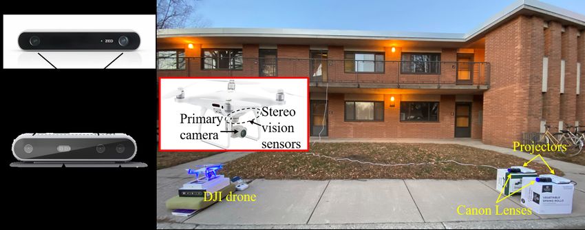
(a) Human binocular vision                (b) Camera stereo vision                (c) Triangulation in depth estimation

                                            Figure 2: Depth estimation in stereo vision.

2     Background                                                        in similar triangles, we have:

In this section, we briefly introduce the preliminary back-                                       b b + pr − pl
                                                                                                    =           ,                      (1)
ground knowledge of DoubleStar, including the foundation                                          z    z− f
of depth estimation from stereo vision and the lens flare effect
in optical imaging.                                                     where z is the depth of point P, f is the focal length of the
                                                                        camera, b is the baseline (distance between the two camera
                                                                        optical centers), pl − pr is the disparity between PL and PR .
2.1    Depth Estimation from Stereo Vision                              Therefore, we can derive the depth of point P as:

Stereo vision-based depth estimation transforms 2D images                                                  f ·b
                                                                                                    z=           .                     (2)
into the perception of the 3D depth map, which contains in-                                              pl − pr
formation related to the distance of the scene objects from the
stereo camera [62]. Depth estimation algorithms are mostly              Triangulation relies on the stereo matching, which establishes
used in autonomous systems to detect and avoid obstacles.               the pixel correspondence between primitive factors in images,
The main idea of depth estimation using a stereo camera                 e.g., PL in the left image corresponds to PR in the right image
involves the concept of stereo matching and triangulation.              in Fig. 2b. Once the stereo correspondence is established, we
   In essence, stereo camera resembles human binocular vi-              can compute each pixel’s disparity in the images to form a
sion shown in Fig. 2a, which is composed of two lenses with             disparity map, which can be converted into a 3D depth map
a separate image sensor for each lens, i.e., left image and right       using Eq. (2). However, certain interference factors, such as
image in Fig. 2b [61]. Binocular disparity in Fig. 2a refers            illumination, noise, and surface physical characteristics, could
to the difference in the image location of an object seen by            induce ambiguous correspondence between points in the two
the left and right eyes, resulting from the eyes’ horizontal sep-       images, e.g., the depth estimation algorithm falsely takes PL
aration. Binocular disparity is the basis for extracting depth          in the left image as the correspondence of QR in the right
information from 2D retinal images in stereopsis [60]. For              image in Fig. 2b. Such ambiguous correspondence caused by
example, in Fig. 2a, PL and PR represent the corresponding              stereo mismatching may lead to inconsistent interpretations
images of P shown on the left and right retinas, while QL               of the same scene, aggravating the false depth calculation.
and QR are the corresponding images of Q. The binocular
disparities introduce a difference in the sensed depth of P and
Q. Likewise, the disparity in the stereo camera refers to the
difference in the coordinates of similar features in two images,
e.g., PL and PR in Fig. 2b.
   Triangulation method is used by stereo vision to calculate
depth [4]. For example, in Fig. 2c, OL and OR represent the left
and right optical centers in the stereo camera. The intersection
points PL and PR are on the left and right images, respectively.
The depth of point P is calculated using similar triangles,                              (a)                               (b)
4PL PPR and 4OL POR , donated as 4PL PPR ∼ 4OL POR .
Suppose the horizontal axis values of PL and PR are pl and pr ,         Figure 3: (a) Lens flare effect; (b) the relationship between
respectively. Since the ratio of corresponding sides is equal           the light source and the orb’s position.

                                                                    3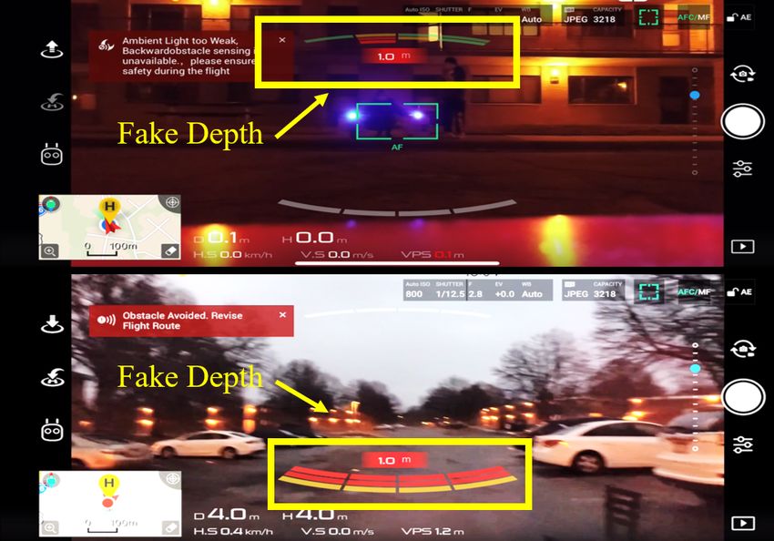
(a) Left and right images                           (b) Depth map                        (c) 3D point cloud

                   (d) Left and right images                           (e) Depth map                         (f) 3D point cloud

Figure 4: DoubleStar on ZED stereo camera during the daytime. (a) to (c) shows the example of X-shape beams attack from 9m
away, and (d) to (f) showcase the trapezoid-shape orbs attack from 2m away. In the depth map, 100% white means the closest
distance and black means the furthest. The 3D point cloud is the reconstruction of the 3D scene based on the depth map.

2.2     Lens Flare Effect                                                          then we illustrate the main experimental observations that
                                                                                   lead to the design of DoubleStar.
Lens flare effect [14, 29] is a phenomenon caused by the
scattering and reflection of a bright light through a non-ideal                      The main root cause of the vulnerabilities in depth esti-
lens system, where several undesirable artifacts appear on                         mation algorithms is their lack of higher-order perceptions.
an image (Fig. 3a). Ideally, all light beams should pass di-                       Unlike human perception, such algorithms do not base their
rectly through the lens to reach the image sensor, and they                        decisions on personal experience. Instead, they aim to match
will form a bright glare in the image. However, due to lens                        similar features (e.g., shapes, colors) with high confidence
imperfections, a small portion of the light will be reflected                      as stereo correspondence, as long as they are in relatively
several times within the lens system before reaching the im-                       reasonable positions in the left and right images. Therefore,
age sensor. Such reflections will result in multiple artifacts on                  most depth estimation algorithms can be affected by physical
the image. Under normal light conditions, these artifacts are                      perturbations. Our experiments demonstrate that strong light
usually invisible. However, when a strong light source (e.g.,                      beams and lens flare orbs can induce wrong depth perception
sun, light bulb, projector) is present, the lens flare becomes                     due to the light beams mismatching and false orbs matching.
more visible and washes out the entire image.                                         Light Beams Mismatching. As shown in Fig. 4a, an at-
    Anti-reflection coatings on the lenses of the commercial                       tacker injects the light beams with the same projection inten-
cameras are often used to mitigate the lens flare effect by                        sity using two projectors (i.e., P and Q) into the right and
filtering out most reflections [22], but these lenses still suffer                 left cameras, respectively. It can be observed that one of the
from the green-color flare orb if a strong white-light source                      injected light sources is brighter than the other one when
is present. Note that, according to our experiments, the rela-                     received by the camera, which becomes a more prominent
tionship between the green-color orb’s position and the white-                     feature in the image. For example, Q is targeting the left cam-
light source is centrosymmetric as illustrated in Fig. 3b3 . In                    era, so the light source shown on the left image from Q is
fact, most of commercial cameras nowadays have applied the                         brighter than that from P. Such phenomenon causes the depth
anti-reflection coatings [12].                                                     estimation algorithms to mismatch the two highlighted light
                                                                                   sources in the images as the same object due to the afore-
                                                                                   mentioned weakness in depth perception. As a result, a fake
3     Vulnerability in Depth Perception                                            near-distance depth is created in the depth map (Fig. 4b) and
In this section, we first present the vulnerabilities of depth                     visualized in the 3D point cloud (Fig. 4c). By adjusting the
perception in computer vision exploited by DoubleStar, and                         distance between projectors and the stereo camera, as well as
                                                                                   the distance between two projectors, different fake obstacle
   3 In crystallography, a centrosymmetric point group contains an inversion
                                                                                   depths can be created.
center as one of its symmetry elements. For example, points M and N in Fig.
3b are centrosymmetric to each other, i.e., if the coordinate of M in the 2D         False Orbs Matching. Fig. 4d shows an example that the
image is (a, b), the coordinate of N will be (−a, −b).                             two orbs generated by the strong light sources in the stereo

                                                                               4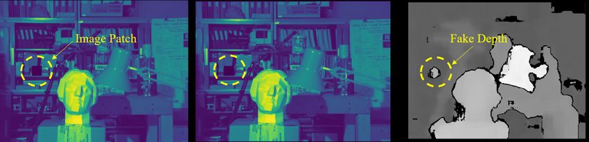
(a) X-shape attack                      (b) Trapezoid-shape attack                   (c) Triangle-shape attack

Figure 5: Three different attack patterns are used in beams and orbs attacks. The orange circle represents the appearance of the
injected light (glare) in the image, and the dotted white circle stands for the position of the light source which is not aiming at the
camera. Green small circles stand for the orbs.

images can mislead the depth perception to falsely identify              5     DoubleStar
them as a 3D obstacle. By matching them as the stereo cor-
respondence of one another, the targeted depth estimation                This section introduces the design of DoubleStar, including
algorithm outputs a fake depth in depth map (Fig. 4e) and a              the beams attack and orbs attack, and analyzes these attacks
corresponding 3D fake obstacle in 3D point clouds (Fig. 4f).             via mathematical models.
Due to the centrosymmetry of the light source and the orb,
the attacker is able to adjust the angle of the injected light
to control the orb’s position. Exploiting such a phenomenon,
theoretically, an attacker could adjust the positions of the two         5.1    Attack Overview
orbs in the stereo camera to manipulate the fake depth values.
                                                                         DoubleStar exploits the vulnerabilities in the depth percep-
                                                                         tion. Certain interference factors can cause ambiguous cor-
4   Threat Model                                                         respondences between points in the two images, which can
                                                                         lead to alternative interpretations of the scene. We design
In this section, we present the threat model of this work, in-           the beams attack using two light sources to form glares on
cluding the attack goal, the attacker’s capability, and the attack       the images which can cause false stereo correspondence in
scenarios. The attacker’s goal is to disrupt regular operations          depth estimation algorithms and further lead to fake depth
of autonomous systems by injecting fake depth, and further               creation. Besides, when a light source is targeting the camera,
lead to unintended system behaviors. For example, an attacker            the lens flare effect will bring in an orb in the image which is
can force a drone into a severe crash, e.g., hitting a tree, by          centrosymmetric to the injected light source. The orbs attack
changing the depth of a real obstacle.                                   mainly utilizes this phenomenon to fool the depth estimation
   Our attack is a fully black-box attack against general stereo         algorithms by matching the two generated orbs in two images
vision based depth estimation algorithms used in OA systems.             as the stereo correspondence. Fig. 5 presents the design of the
An attacker has no physical access to the hardware or firmware           beams attack and orbs attack with three attack patterns. P and
of the attack target, nor does he/she have access to the camera          Q are the light sources, e.g., projectors. Their corresponding
images. An attacker also has no prior knowledge about the                position in the left and right image in the stereo cameras are
depth estimation algorithms used in the OA system.                       PL , QL , PR , QR , respectively. A green orb is centrosymmetric
   We consider an attack target is equipped with a stereo cam-           to the injected light source in each image.
era for OA. For drone attacks, we further assume the drones                 We design three different patterns for both beams and orbs
operate in a flying mode, such as Positioning (P) Mode in DJI            attacks, as shown in Fig. 5: 1) X-shape attack (Fig. 5a): P is
drones [8] or Loiter Mode in Ardupilot [2], where a human                pointing to the right camera while Q is aiming at the left cam-
operator controls the drone with the assistance of the OA.               era. Trapezoid-shape attack (Fig. 5b): P is targeting the left
However, once an obstacle is detected within its OA range,               camera whereas Q is pointing to the right camera. Triangle-
the OA in the autonomous system makes decisions preceding                shape attack (Fig. 5c): P and Q are covering the left and right
any human input, i.e., it takes precedence over the pilot/driver.        cameras at the same time. Here, we define the depth of near-
As an example, when an obstacle is detected in front of the              distance fake obstacles as the one smaller than the true depth
drone within the safety margin of OA, the drone will stop                of the light source, and define the depth of far-distance fake
moving forward even if the pilot pushes forward the throttle.            obstacles as the one greater than the true depth.

                                                                     5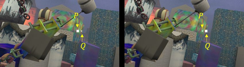
(a) Beams attack: b > d      (b) Beams attack: b < d              (c) Orbs attack: b > d                  (d) Orbs attack: b < d

Figure 6: Obstacle positions in beams attack (a-b) and orbs attack (c-d) in two attack scenarios. b is the baseline of the stereo
camera, and d is the distance between the two light sources. P and Q represent the positions of the two light sources, and OL
and OR represent the left and right optical centers of the stereo camera. z is the true depth of the light sources, corresponding
to the perpendicular distance between the projectors and the stereo camera. PL and QL are the intersections of P and Q on the
left image, while PR and QR are the intersections on the right image. Q0L , Q0R , PL0 and PR0 are the location of the orbs. FX and FT
represent the fake obstacle positions corresponding to the X-shape and trapezoid-shape attack, where the red color implies the
existence of fake obstacles while blue implies their non-existence in theory.

5.2     Beams Attack                                                   algorithm outputs the true depths of P and Q. However, in a
                                                                       real-world attack, when the injected light intensities on the left
5.2.1    Attack Design                                                 and right cameras slightly differ, the triangle-shape attack will
                                                                       be transformed into the X-shape or trapezoid-shape attack.
X-shape Attack. Using X-shape attack pattern (Fig. 5a), P
and Q form the corresponding glares PR and QL , respectively.
                                                                       5.2.2   Mathematical Modeling and Analysis
With certain constraints on the perpendicular distance and
included angle between the light sources and the stereo cam-           Since the triangle-shape attack is essentially the X-shape or
era, the targeted depth estimation algorithm falsely takes PR          trapezoid-shape attack, we conduct a mathematical analysis of
as the stereo correspondence of QL . As a result, it outputs a         these two most basic attack patterns. Figs. 6a and 6b present
near-distance fake depth since the disparity becomes larger            the mathematical model for beams attacks.
than the real one. Fig. 4a illustrates a real-world scenario of           Suppose the depth of FX and FT are zx and zt , respectively.
the X-shape beams attack which produces a near-distance                The corresponding coordinates of PL , PR , QL and QR are pl ,
fake depth (Fig. 4b), when the real depth of the projectors are        pr , xl and xr . Based on Eq. (2), the disparity of point P is:
9m away from the stereo camera.                                        pl − pr = f z·b . Moreover, since 4OL QP ∼ 4OL QL PL , we
   Trapezoid-shape Attack. As shown in Fig. 5b, by using                              d
                                                                       have: zf = ql −p l
                                                                                          , ql = f z·d + pl . The disparity of FX is:
the trapezoid-shape attack pattern, the glares PL and QR are
generated by P and Q. Similarly, with certain constraints                                        f ·d             f · (d + b)
                                                                                  ql − pr =           + pl − pr =             .          (3)
on the distance and angle, the depth estimation algorithm                                          z                    z
matches PL and QR as the same object. However, it only                 Thus, from the Eqs. (2) and (3), we obtain the fake depth zx :
works when the glares approach the center of the image, oth-
erwise, no fake depth can be generated, the reason of which                                                b
                                                                                                  zx =        · z.                       (4)
is explained in Section 5.2.2. Since the glares cover multiple                                           d +b
pixels, the algorithm will output a far-distance fake depth,           Obviously, zx < z, which indicates that the fake obstacle FX
overshadowing the real obstacle depth. The generated fake              created by the X-shape attack is nearer to the stereo camera
depth merges into the background depth, which cannot be                than the light sources as shown in Figs. 6a and 6b. Note
identified by human eyes. However, we confirm that the fake            that when 0 < zx < f , FX is non-existent. This follows the
depth can be perceived by the stereo cameras.                          optical imaging principle that the fake depth cannot be shorter
   Triangle-shape Attack. Fig. 5c shows the triangle-shape             than the focal length f . Such scenario appears either when
beams attack where the two light beams cover both the left             the two projectors are too far away from each other or the
and right cameras. Hypothetically, when the injected light             perpendicular distance between the projectors and the stereo
intensities from P and Q reflected on both left and right images       camera is too small. In other words, if d is too large or z
are equal to each other, the depth estimation algorithm will           becomes too small, the fake obstacles may not be created.
match PL and PR as the same object. Similarly, QL and QR               The analysis of a failed attack scenario can be found in the
will also be matched as the stereo correspondence. Thus, the           Appendix A.2.

                                                                   6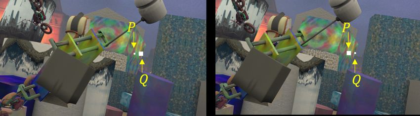
Similarly, zt can be expressed as:                                    Q0R , PL0 and PR0 are q0l , q0r , p0l and p0r , respectively. In the orbs at-
                                                                        tack, we also consider two scenarios based on the relationship
                                 b                                      between b and d.
                         zt =       · z,                     (5)
                                b−d                                        Since the orbs and their corresponding injected lights are
                                                                        centrosymmetric, p0l , p0r , xl0 and xr0 have the exact opposite
where zt > z if b > d, and zt < 0 if b < d. Correspondingly,            value as pl , pr , xl and xr , respectively. Following the deriva-
as shown in Fig. 6a, when b > d, FT has a larger depth. Con-            tion in Section 5.2.2, zx and zt for orbs attack are:
versely, when b < d, FT appears on the opposite side of the
stereo camera, which is non-existent. However, the injected                                                    b
                                                                                                    zx = −        · z,                          (6)
light is not a single pixel, instead, it contains several blocks                                             d +b
with multiple pixels in the image. The depth estimation al-
gorithm will try to match these blocks in the left and right                                               b
images, which could result in a far-distance fake depth. This                                        zt =     · z.                   (7)
                                                                                                        d −b
special case is marked in blue in Fig. 6b.                              Since zx < 0, it means that FX is non-existent regardless of the
                                                                        value of d. For the depth of FT , when b < d, zt < z, which in-
                                                                        dicates that a near-distance depth can be created by trapezoid-
5.3     Orbs Attack
                                                                        shape attack in Fig. 6d. When b > d, zt < 0, FT appears on the
5.3.1   Attack Design                                                   other side of the stereo camera indicating the non-existence
                                                                        of the FT . However, since the orbs consist of multiple pixels,
X-shape Attack. Fig. 5a shows that the generated green orbs             it is still possible for a far-distance fake depth to be formed.
are centrosymmetric to the glares QL and PR in the left and             The three special cases are marked in blue.
right images (see Appendix A.1). Given proper attack dis-                   It is worth noting that when d = b, no fake depth can be
tance/angle, the depth estimation will falsely match the two            generated in both attacks. In summary, (1) the beams attack
orbs as the same object. However, the attack works only when            works with all three attack patterns when b > d, and with
the orbs approach the image center, otherwise, no fake depth            X-shape and triangle-shape attack pattern when b < d; (2) the
is created (see Section 5.3.2 for the reason). Since orbs con-          orbs attack works with trapezoid-shape and triangle-shape
sist of multiple pixels, the algorithm can output a far-distance        attack when b < d. Comparing the blue and red fake obstacle
fake depth, whose exact value depends on the orbs’ positions.           points in beams and orbs attack (Fig. 6), we can see that the
   Trapezoid-shape Attack. Since the orb and the glare are              beams and orbs attacks complement each other’s performance.
centrosymmetric, the orb appears at the right of the PL in the          As a result, in a real-world attack, fake obstacles generated
left image, and at the left of the QR in the right image (Fig.          by beams attack and orbs attack can co-exist, and these two
5b). As mentioned before, due to the weakness of the depth              attacks can operate in concert to enhance the attack capability.
perception, the depth estimation algorithm matches the two
orbs as the same object and outputs a near-distance fake depth
since the disparity is larger than the real one. Fig. 4d shows          6     Simulation
that a real-world trapezoid-shape orbs attack is able to create
                                                                        In this section, we first evaluate DoubleStar against drone
a near-distance fake depth (Fig. 4e) by matching the two orbs
                                                                        in a simulation environment. Then, we simulate the attacks
in the left and right images as the stereo correspondence.
                                                                        towards various stereo depth estimation algorithms to verify
   Triangle-shape Attack. Since the projection from P and               the attack impact.
Q covers both cameras, four glares PL , QL , PR , and QR appear
in the left and right images. Based on the centrosymmetric
relationship between the glare and orb, two orbs appear in              6.1     Drone Attack Simulation
each image. The depth estimation matches the orbs in the left           We simulate DoubleStar drone attacks using Ardupilot [2]
and right image correspondingly. Due to the centrosymmetry,             and AirSim [31]. AirSim is an autonomous system simu-
the depth estimation outputs two fake obstacle depths that are          lator created by Microsoft, which is used to collect virtual-
the same as the light source’s real depth. However, in practice,        environment data in our simulation, while Ardupilot, a popular
since the attacker cannot precisely control every single pixel          drone project, is used to simulate DoubleStar on drones.
in the image, the stereo correspondence will occur either like             Fig. 7 shows the workflow in the virtual environment.
Fig. 5a or Fig. 5b. As a result, the fake depth is still created.       Ardupilot is used for simulating MAVProxy as the ground sta-
                                                                        tion, and ArduCopter as the drone. AirSim provides the sensor
5.3.2   Mathematical Modeling and Analysis                              inputs to the ArduCopter. The user first sends commands to
                                                                        ArduCopter via MAVProxy. Next, ArduCopter sends its states
Figs. 6c and 6d show the mathematical modeling of orbs at-              to AirSim, which provides a simulated environment. After
tack. The corresponding horizontal coordinates of the orbs Q0L ,        that, AirSim sends the sensor inputs back to ArduCopter, and

                                                                    7
(a) Attack BM

Figure 7: The simulation workflow of DoubleStar with
Ardupilot and AirSim.

the drone’s OA system processes the received data and makes                                       (b) Attack SGBM
the flying decisions to avoid the obstacles.
   To attack the drone, we design a depth manipulator and em-            Figure 9: An image patch is attached to left and right images
bed it between ArduCopter and AirSim. By injecting different             in both BM and SGBM depth estimation algorithms, and the
fake obstacle depths in a realistic scenario, we successfully            result confirms that our attack can compromise these depth
demonstrate that our attack can achieve real-time drone con-             estimation algorithms.
trol. For example, to move the drone forward while ignoring
the real obstacle in its path, we can generate a fake target that
is apparently far away. The bright beams would overwhelm                 tects the fake obstacle, it will retreat, only to revert course
the sensors and make the actual barriers invisible. Conversely,          when the barrier suddenly disappears. Therefore, the attack
we could also inject a seemingly close object to stop the drone.         forces the drone to go back and forth alternately, resulting in
Remarkably, pushing the drone away from its original course              front-to-back body shaking. Similarly, we can also generate
is also possible if the attacker creates a fake object that floats       the fake depth on its front left and right alternately within a
at a constant distance from the drone by its side. Fig. 8 shows          short time interval to shake the drone sideways. The demo
such an example, where the attacker injects a fake depth to the          video is available on the website.
front right position of the drone. The drone under attack drifts
away from its heading direction to the left, even as there is no         6.2    Attack Simulation on Stereo Depth Esti-
real obstacle present near the drone. We further demonstrate
                                                                                mation Algorithms
this attack in a real-world experiment in Section 7.5.
   Other useful drone manipulations, such as drone body shak-            Attacking Classic Algorithms. We simulate the attack to-
ing and moving backward, are also feasible. For example, by              wards two classic stereo depth estimation algorithms, i.e.,
merely injecting a fake object within the drone’s OA dis-                block matching (BM) [37] and semi global block matching
tance, the drone will move backward. By manipulating the                 (SGBM) [38]. As shown in Fig. 9, we embed a patch on
depth within its OA distance threshold, DoubleStar could                 both images, which deceive both algorithms in generating
continue as the OA system attempts to steer the drone away.              unreliable depths. These classic non-AI-based depth estima-
We consider two shaking patterns for shaking the drone: (1)              tion algorithms are still pervasive in real devices, due to their
front-to-back shaking and (2) left-to-right shaking. In the first        low computational complexity and short real-time delay [70].
case, we place the fake obstacle depth intermittently with a             However, the state-of-the-art depth estimation algorithms are
specific time interval, e.g., 0.5 seconds. When the drone de-            mostly driven by AI models, such as convolution neural net-
                                                                         work (CNN) and recurrent neural network (RNN) [23]. These
                                                                         algorithms leverage deep neural network (DNN) to learn rep-
                                                                         resentations from image data to extract the depth information.
                                                                            Attacking AI-based Algorithms. To verify the generality
                                                                         of DoubleStar, we test the attack on three state-of-the-art AI-
                                                                         based stereo depth estimation algorithms, i.e., DispNet [30],
                                                                         PSMNet [6], and AANet [51]. DispNet is an end-to-end train-
                                                                         able framework for depth estimation, where a correlation layer
 (a) Flying trajectory on the zoom- (b) Real flying environment in       is used to measure the similarity of left and right image fea-
 in map in Ardupilot                AirSim                               tures. PSMNet takes a different approach by directly con-
                                                                         catenating left and right features, and then 3D convolutions
Figure 8: The ArduCopter under attack drifts away when there             are used to aggregate the costs to achieve higher accuracy.
is no real obstacle near the drone.                                      AANet uses a cost aggregation method based on sparse points

                                                                     8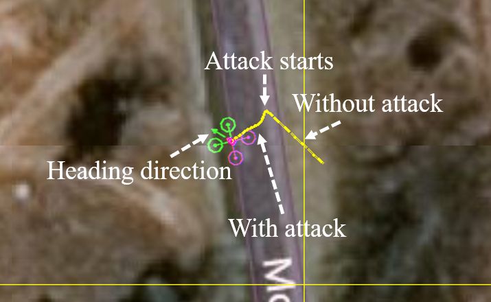
(a) X-shape beams attack

                 (b) Trapezoid-shape beams attack                           (a) DispNet          (b) PSMNet             (c) AANet

Figure 10: Two image patches, P and Q, are attached to left           Figure 11: Depth maps from DispNet, PSMNet, and AANet.
and right benign images.                                              Each column, from up to down, represents benign depth map,
                                                                      depth map from X-shape beams attack, and depth map from
                                                                      trapezoid-shape beams attack. The fake depths are circled.
in conjunction with neural network layers to achieve a faster
inference speed while maintaining comparable accuracy.
   Fig. 10 shows examples of X-shape and trapezoid-shape
beams attacks. From Figs. 10a and 10b, we can see two small
image patches are embedded in the stereo image, correspond-
ing to the two light beams (i.e., P and Q). We take this adver-
sarial stereo image pair as the input to the three algorithms.
The corresponding outputs of the three algorithms are shown
in the Fig. 11. We can see that all three algorithms can be
deceived by X-shape beams attack, since a near-distance fake                (a) DispNet          (b) PSMNet             (c) AANet
obstacle is generated as expected. Regarding the trapezoid-
shape beams attack, we expect to see a far-distance fake depth        Figure 12: Depth maps from DispNet, PSMNet, and AANet.
in the image according to our mathematical analysis. How-             For each column, the upper depth map is from X-shape beams
ever, since a far-distance fake obstacle is blended into the          attack, and the lower one is from trapezoid-shape orbs attack.
background in the depth map, it can hardly be observed. Note          The fake depths are circled.
that, the fake depth value depends on the position of the in-
jected patches, e.g., by separating P and Q away from each
other in the stereo image pair, the fake depth value grows.           cameras, ZED and Intel RealSense D415. For simplicity, we
   Verifying the Attack. We collect the adversarial stereo            refer DJI Phantom 4 Pro V2 as the DJI drone, ZED stereo
images from the real-world attack and use them as input to            camera as ZED, and Intel RealSense D415 stereo camera as
these three algorithms. Specifically, we use the stereo image         RealSense. We select DJI drone due to its high popularity and
pairs of X-shape beams attack and trapezoid-shape orbs attack         state-of-the-art stereo vision based OA systems [10]. ZED and
in Figs. 4a, 4d as input. Their corresponding fake depth maps         RealSense are chosen since they are specially designed for au-
from the three algorithms are shown in Fig. 12. It can be             tonomous robotic systems, both of which use the cutting-edge
seen that except the orbs attack on AANet, all the attacks            AI-based algorithms to compute the depth [16, 69].
successfully inject fake depth information. For the orbs attack          The experiments aim to measure (1) the range within which
on AANet, the orbs disappear from the depth map, which may            the fake obstacle can be generated, (2) the range of attack
have been smoothed out by the AANet algorithm.                        distance, and (3) the range of attack angle within which we
                                                                      can successfully launch the attacks.

7   Evaluation                                                        7.1    Experimental Setup
In this section, we evaluate DoubleStar on the depth                  The evaluation setup is shown in Fig. 13, where we have the
estimation-based OA systems used in autonomous systems.               DJI drone on the left and two projectors combined with two
Specifically, we showcase proof-of-concept DoubleStar on              zoom lenses on the right in an outdoor environment. The DJI
a commercial drone, DJI Phantom 4 Pro V2, and two stereo              drone could be switched into ZED or RealSense according

                                                                  9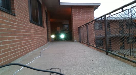
Table 1: Fake depth range on the DJI drone at night and
                                                                         during the daytime with different attack patterns. Expected
                                                                         fake depth is derived from the mathematical model. “None"
                                                                         means no fake depth can be successfully injected.
                                                                                        Expected Fake
                                                                         Attack                            Fake Depth Range at Night (m)     Fake Depth Range in the Day (m)
                                                                                        Depth (m)
                                                                         Distance (m)
                                                                                        X      Trapezoid   X         Trapezoid   Triangle    X           Trapezoid   Triangle
                                                                         1              0.5    0.5         0.5       0.5         None        1.5         1           None
                                                                         2              0.5    0.5         0.5       0.5         None        0.5 - 1     8           None
                                                                         3              0.5    0.5         0.5       0.5         0.5 - 16    1 - 1.5     3           None
                                                                         4              0.5, 1 1           0.5 - 1   10.5        0.5 - 16    0.5 - 1.5   10 - 11     0.5 - 11
Figure 13: Outdoor attack experimental setup: the DJI drone              5              0.5    1           0.5       11          0.5 - 16    0.5 - 2     5 - 11      1 - 5.5
                                                                         6              0.5    1           0.5 - 1   12.5        10.5 - 16   1-2         5 - 11      1 - 11
is on the left and two Epson PowerLite 1771W projectors [11]             7              0.5    1           1         12 -16      6.5 - 16    None        None        0.5 - 14.5
                                                                         8              1      1           0.5-1     12-16       6.5 - 16    None        None        1 - 14
combined with two Canon EF 75 − 300mm zoom lenses are                    9              1      1           None      None        1 - 16      None        None        None
                                                                         10             1      1.5         None      None        1.5 -10.5   None        None        None
on the right. We also conduct the experiments on ZED and                 11             1      1.5         None      None        1 - 16      None        None        None
RealSense in the experiments. All three attack devices have              12
                                                                         13
                                                                                        1.5
                                                                                        1.5
                                                                                               1.5
                                                                                               2
                                                                                                           None
                                                                                                           None
                                                                                                                     None
                                                                                                                     None
                                                                                                                                 1.5 - 16
                                                                                                                                 1.5 - 16
                                                                                                                                             None
                                                                                                                                             None
                                                                                                                                                         None
                                                                                                                                                         None
                                                                                                                                                                     None
                                                                                                                                                                     None
a pair of stereo vision sensors. The DJI drone has a primary             14             1.5    2           None      None        10.5 - 14   None        None        None
                                                                         15             1.5    2           None      None        16          None        None        None
camera at the bottom and RealSense has extra infrared pro-               16             1.5    2           None      None        None        None        None        None

jectors and an RGB camera.

                                                                         7.2       Fake Depth Range
to the setup of different experiments. The throwing ratio is
defined as the ratio between the projection distance and the             Table 1 summarizes the range of fake obstacle depth that the
size of the projection screen. If an attacker aims to perform            attacks can achieve on the DJI drone during the daytime and
long-distance attacks, he/she would need the projector to have           at night. The default value of the projection light illuminance
a larger throwing ratio to concentrate the light beams.                  is 1.6×10⁴ lux without connecting to any source. We perform
   The size of the lenses on the stereo camera is tiny, e.g., the        each attack pattern with different attack distances and record
area of the lens on ZED is 1.3 × 10⁻⁴ m2 . The throwing ratio            all possible fake depths it generates.
of our projector is also very small, i.e., 1.04 – 1.26, which               The results show that DoubleStar can achieve maximally
means that the projection screen area is at most 0.62 m2 at              13m attack distance when the fake depth is under 6m (i.e.,
1m. Comparing 1.3 × 10⁻⁴ m2 with 0.62 m2 , we can see that               a successful attack). Our attacks can achieve up to 15m in
less than 1% of the projection light can be injected into the            distance, in which case the depth of a real near-distance object
lens. Therefore, to further extend the attack distance, we inte-         is converted into the depth of a far-away fake obstacle. Using
grate each projector with a Canon zoom lens (i.e., Canon EF              all three attack patterns, our attack can generate various fake
75-300mm) [29]. In our experiments, the maximum throwing                 depths with the attack distance ranging from 3 − 8m at night
ratio is increased to 30, when the focal length is adjusted to           and 4 − 6m in the day. However, there are a few cases when
300 mm, which implies that 2.5 × 10⁻³ m2 projection screen               only partial attack patterns work. Specifically, when the at-
area can be achieved at 1m. Thus, around 12% of the projec-              tack distance is 1 − 2m, the triangle-shape attack fails in both
tion light can arrive at the lens, making the long-range attack          ambient light conditions. The reason is that in these cases the
feasible.                                                                width of the projection screen is smaller than the baseline,
   Since we have no access to the DJI drone’s sensor data, we            and no projection light can enter the stereo camera. When the
use the DJI drone to read the depth in meters and use the ZED            attack distance is 3m, the triangle-shape attack works at night
to verify the left and right images, depth map, and 3D point             but fails in the day due to the strong ambient light. In fact,
cloud. For RealSense, as it does not give us access to its left          during the daytime, only the marginal projection light can
and right images, we will only check the depth map to verify             enter the stereo camera, resulting in an injected light intensity
the success of our attack. For the experiments on the DJI                that is too weak to deceive the depth perception. Also, when
drone, we define the attack as successful if the generated fake          the attack distance is more than 8m at night and 6m during the
depth is less than 6m, which is the threshold value to trigger           daytime, both trapezoid- and X-shape attacks fail. The reason
actions of the OA system. For the experiments on ZED and                 is that the divergent light beams traversing a long distance
RealSense, we record it as a success as long as a near-distance          significantly weaken the injected light intensity.
fake depth can be seen in the depth map. We perform each                    It is worth noting that modern cameras are usually equipped
attack pattern 3 times in every experiment.                              with the auto exposure (AE) control mechanisms [25], which
   During the experiments, the distance between the two pro-             automatically balance the brightness of the captured image.
jectors is fixed as 1m. The environmental ambient light levels           The exposure increases if the overall brightness turns dark,
are 4000lux and 0lux for day and night, respectively. All the            and vice versa. Our results show that the orbs attacks usually
experiments are conducted outdoor. Unless otherwise speci-               fail during the day, while the beams attacks succeed. This
fied, these parameters are the default for all experiments.              phenomenon is likely caused by AE, when the brightness of

                                                                    10
can be up to 7m during the day. The attack range increases
proportionally with the increasing of the projection inten-
sity at the beginning. However, when the luminosity reaches
8.4 × 10³ lux, the attack range value plateaus and remains the
same ever since. It is because as the distance increases, the
light source becomes less predominant in the image. In addi-
tion, due to the AE control under the strong ambient light, the
camera could view the background environment more clearly.
(a) Attack range on the DJI drone. (b) Attack range on ZED.
Thus, false stereo correspondence matching is avoided.
Figure 14: Attack range w.r.t. projection illuminances. Our results indicate that: (1) as the perpendicular distance
between the DJI drone and the projector increases, a stronger
projection intensity is required to generate the fake obstacle
the injected beams induces a drop of lightness in the image depth; (2) launching successful DoubleStar at night is easier
background. As a result, the orbs become less visible. than during the daytime due to the influence of the ambient
Moreover, in order to launch the trapezoid- and X-shape light; (3) during the daytime, even with a stronger projection
attacks, the attacker should avoid lights overlapping at the intensity, it is very difficult to achieve a larger attack distance
drone side. To achieve that, the attacker can only use marginal because the projected light source becomes less predominant
light to launch these two attack patterns. As a result, the and the environment becomes clearer in the image.
injected light intensity becomes too weak to attack effectively.
However, overlapping is not an issue for the triangle-shape Visualization Results from Stereo Camera. For the at-
attack. That is why the triangle-shape attack can achieve the tack on ZED, we visualize the image depth map and 3D point
longest attack distance. In summary, the range of fake depth is cloud to evaluate the range of attack distance and explore the
0.5 − 16m. This range covers all the possible depths that can relationship between the beams attack and orbs attack.
be sensed by DJI drone’s OA system, which makes real-time
We conduct the experiments only in the daytime to better
drone control possible.
observe the depth. By repeating the experiments with different
projection intensities, we record all attack results for different
7.3 Range of Attack Distance attack distances using shades of blue as shown in Fig. 14b. In
the figure, “2" indicates the case when fake depths from both
The range of attack distance is the key evaluation criterion
the beams and orbs attack are observed; “1" indicates that
in our attack, since no prior work has ever achieved a long-
only fake depth from the orbs attack is observed; “0" indicates
range drone sensor attack. With the projector’s default light
no fake depth is observed. It can be seen that when the attack
illuminance, we can achieve up to 13m attack range at night
distance is 1 − 2m, only the orbs attack works. It is because
and 7m attack range during the daytime. Further, we explore
the disparity of these two projectors is too large to be matched
the impact of the projection light intensities on the range of
as the same object, which has been discussed in Section 5.2.2.
attack distance on both ZED and DJI drone.
When the distance is from 3 − 8m, both the attacks can be
Attack Range Results from Drone. We repeat the exper-
observed in the depth map and 3D point cloud. However, when
iments with different projector intensities on the DJI drone,
the distance increases to 9 − 11m, the fake depth can still be
and record the longest distance where our attack is successful
observed from the orbs attack with stronger light intensities,
as the corresponding attack range.
but not from the beams attack. This can be attributed to the
Fig. 14a presents the attack distance range on DJI drone weak light intensity which is insufficient for beams attack
with various projection intensities. Each point in the figure to succeed, but the lens flare effect is unaffected. Note that
refers to the longest attack distance at which the fake depth both attacks are invisible with a weaker projection intensity
can be observed. We determine an attack as successful when because of the low luminosity. When the distance goes beyond
the fake depth is observed by the controller. The results show 12m, the light is too weak to execute any successful attack due
that at night our attack can achieve up to 15m with the highest to the more divergent light beam. We observed that within the
projection intensity, and up to 3m with the lowest projection successful range, the orbs attack usually outperforms beams
intensity. The attack range increases dramatically with the in- attack within the short attack range, whereas beams attack
creasing of the projection illuminance below 1.4 × 10⁴ lux and becomes more evident as the attack range increases.
grows smoothly afterwards. The reason behind it is that the
projection illuminance has a more dominant impact than the Our results indicate that: (1) merging the beams attack
attack distance at the beginning since the light is very concen- with orbs attack helps increase the attack range; (2) the orbs
trated; whereas, the light beam becomes more divergent be- attack is more resistant to the weak projection intensity than
yond 12m, which limits the injected light intensity even with the beams attack; (3) DoubleStar can achieve up to 11m in
a higher projection illuminance. On the other hand, our attack the day with a strong projection intensity on ZED.
11(a) Illustration of three attack an- (b) Horizontal attack angle θh (c) Vertical attack angle θv (d) Spinning attack angle θs
gles
Figure 15: The maximum attack angle with varying achievable attack distances during the day and at night.
7.4 Relative Positions of Attacker and Drone the injected light intensity. However, when the attack distance
is 3 − 6m, θh reaches around 45°, the largest θh at night, in
In this section, we evaluate the attack performance with re- which case both projectors are out of the sensors’ view. This
spect to the relative positions of the attacker and drone. Specif- attack is thus the result of out-of-view lens flare effect.
ically, we define three types of attack angles, including hori- Vertical Attack Angle θv . The vertical FOV of the DJI
zontal attack angle, vertical attack angle and spinning attack drone is +27/-27° [10], i.e., when θv is more than 27°, both
angle. As shown in Fig. 15a, we define the horizontal and projectors are out of the vision sensors’ view. Fig. 15c shows
vertical angle as the included angle between the center point maximum θv with varying attack distances. The range of
of the two attack projectors and the attack target, denoted as θv during the day and night have very similar trend while
θh and θv respectively. Spinning attack angle is defined as the performance in the day outperforms that at night. It can
the included angle between the two projectors and the attack be observed that when the attack distance is at 1m in the
target (θs ) at the ground plane. We perform the experiments daytime and 1 − 4m at night, θv is larger than the vertical
on DJI drone to evaluate the impact of attack angles. FOV, which is mainly caused by the out-of-view lens flare
In all the following experiments, we fix the attack range and effect. The maximum θv is around 40° during the day and
change the horizontal/vertical/spinning attack angles. Then, 45° at night. With the increasing attack distance, θv in both
we record the maximum attack angle to launch a successful scenarios shrinks due to the drop of injected light intensity.
attack, with respect to the varying attack distances z between Spinning Attack Angle θs . Fig. 15d shows the maximum
the attacker and drone in Fig. 15a. θs with varying attack distance. During the day, we can see
Horizontal Attack Angle θh . The horizontal field of view that θs is 60° at 1m. When the attack distance increases, θs
(FOV) of the DJI drone is 60° [10], i.e., when the θh is more becomes less flexible due to the increasing straight-line dis-
than 30°, both projectors are out of the sensors’ view. Fig. 15b tance between the camera and the projector. The larger the
shows maximum θh with respect to different attack distances. distance is, the weaker the injected light becomes and the
During the day time, θh is 18° at 1m. The largest attack smaller the attack angle can be. On the other hand, the attack
angle (29°) can be achieved when the attack distance is 2m. performance improves at night. We achieve the maximum
However, θh decreases beyond 2m, mainly due to the increas- 90° attack angle at 2 − 3m, which is larger than the vision
ing straight-line distance between the camera and the projec- sensors’ horizontal FOV (60°). Even when the light source is
tor. A longer distance results in weaker injected light, which out-of-view, several orbs can still be produced, resulting in a
in turn leads to a smaller attack angle. Note that since the dis- successful orbs attack.
tance between the two projectors is 1m, when the attack angle The results indicate that: (1) the attack angle is more flex-
is 18° at 1m, one projector is already out of the vision sensors’ ible at night than during the day due to the weak ambient
view while the other one is still in the view. Even when the light at night; (2) the range of attack angle becomes narrower
light source is out-of-view, several orbs can still be generated with the larger attack distance in most of the cases due to the
due to the out-of-view lens flare effect (see Appendix A.3), enlarged distance between the camera and the projector; (3)
resulting in a successful orbs attack. Moreover, the light beam during the night, the orbs attack can forge fake depths even
is more concentrated at 1m, making it harder to inject light when the light source is out of the FOV.
into the stereo camera with a wider attack angle.
At night, we can see the overall attack performance is better
7.5 End-to-End Attack Validation
than that during the day because of the absence of the ambi-
ent light. Most of the attack angles are around 30°or below. For end-to-end attack validation, we first illustrate how the
Beyond 7m, θh decreases dramatically due to the decrease of attacker can control the injected fake depth using the math-
12ments to drift the drone away from its original flying path by
continuously injecting fake depths. DJI drone can automati-
cally avoid obstacles rather than simple braking and hovering
in some specific intelligent flying modes, i.e., ActiveTrack
and TapFly [8]. We use ActiveTrack mode in our experiments,
which allows the pilot to mark and track a moving object. To
make the attack device more portable, we use two high-lumen
flashlights [1] to aim the drone. When the drone is tracking a
subject at around 7m away from the attacker, we launch the
attack and observe that the drone drifts away towards another
direction. Moreover, we can slightly adjust the position of the
light sources to change the fake depth locations from left to
right alternately, which effectively shakes the drone. Please
refer to our website for the attack demo.
Figure 16: The attacks on forward and backward vision sen-
sors on the DJI drone at night and in the day, respectively.
The attack results are viewed on the controller. 7.6 Attack Sensitivity Analysis
Aiming Precision. The sensors mounted on flying drones and
moving autonomous vehicles are usually tiny. Thus, aiming
ematical model. To showcase the real-world attack perfor- at the moving targets is quite challenging as shown in recent
mance of DoubleStar, we validate the end-to-end attack on work [5,29,50], since the adversarial attack patterns should ap-
both the flying DJI drone and RealSense camera. Please refer pear at the specific positions in the images or 3D point clouds.
to Appendix A.4 for the RealSense attack validation. Unlike these efforts, our attack relaxes the requirements for
Control and Validation of the Fake Depth. An attacker precise aiming.
can apply the mathematical model in Section 5 to control the To aim the drone, an attacker has to track the target in
fake depth generated at the victim device. For instance, with real-time to ensure the light is projected into the appropriate
d = 1m and b = 0.12m, the injected fake depth of X-shape sensors. The position of the beam is determined by the loca-
beams attack at 4m away is 0.43m from Eq. (4). tion of the projectors; the position of the orbs/glares in the
In our experiments, the near-distance fake depths from X- 2D plane determines the position of the fake obstacle and its
shape beams attack and trapezoid-shape orbs attack are the depth value in the 3D-depth map. To realize the attack in real
ones we use to trigger the drone’s OA, while the far-distance attack scenarios, an attacker first visually estimates the dis-
fake depths are created from trapezoid-shape beams attack tance between the two projectors and the stereo camera, and
and X-shape orbs attack. Since the step size of the depth in the determines the distance between the two projectors based on
drone’s OA system is 0.5m, we manually round the calculated the predetermined fake depth from the mathematical models.
values from mathematical model to its nearest step value. More importantly, our attack can be generalized on different
Table 1 (second column) shows the expected near-distance devices by leveraging coarse-grained control of fake-depths
fake depths from the mathematical model in comparison with using various attack patterns, e.g., X-shape beam attack gener-
the experimental results for X- and trapezoid-shape attacks. ates near-distance fake-depth, whereas trapezoid-shape beam
The results show that most of the injected fake depths from attack generates far-distance fake depth. In drones, a depth
real experiments match with the expected ones. This indicates threshold is used to trigger OA, thus, a precise fake depth is
that the mathematical model can indeed be used to guide the not required. We experimentally validate that a coarse aiming
attack process by adjusting the fake depths. precision is sufficient for a successful attack.
Sudden Braking. To demonstrate the practicality of Although the requirement of aiming precision is not high,
DoubleStar, we launch the attack on a flying drone to induce the attacker does need to inject light into the camera. Par-
sudden braking. We enable the P Mode on the DJI drone, with ticularly, in order to drift the drone away to follow a target
which it simply brakes and hovers when it detects the obstacle trajectory, the attacker should closely follow the movement
on its flying path. Fig. 1 shows our attack towards a flying of the drone. Otherwise, when the light beams become out of
DJI drone from 7m away. Fig. 16 shows the attack effects on the vision sensors’ view, the attack could fail. On the other
backward vision sensors during the daytime and forward vi- hand, with even the slightest movement of the lenses angle, a
sion sensors at night on the controller. We can see that the 1m large difference can be observed on the attack target. Since
fake depth is detected in both cases. The drone starts sending the attacker can control the movement of the lenses, the at-
warnings, and stops moving forward even though the pilot tacker can aim the light beam at the moving target by slightly
pushes the throttle forward on the controller. adjusting the angle of the lens. Based on the real-time feed-
Drifting Away and Shaking. We then perform the experi- back from the drone, e.g., its flying behavior or warnings, the
13You can also read