MCU Comp@s Module For CES48 Central Up Converter
←
→
Page content transcription
If your browser does not render page correctly, please read the page content below
MCU Comp@s Module
               For CES48 Central Up Converter

                     Quick Start User Guide

                               MCU Comp@s for CES48
                                                                          Ref.   4804 872 47812
                                Quick Start User Guide
Alpha Technologies
                           Subject to modifications without notice        Date      03/2012
                     © Alpha Technologies S.A. – Wavre – Belgium - 2012   Ed.       Ed. 020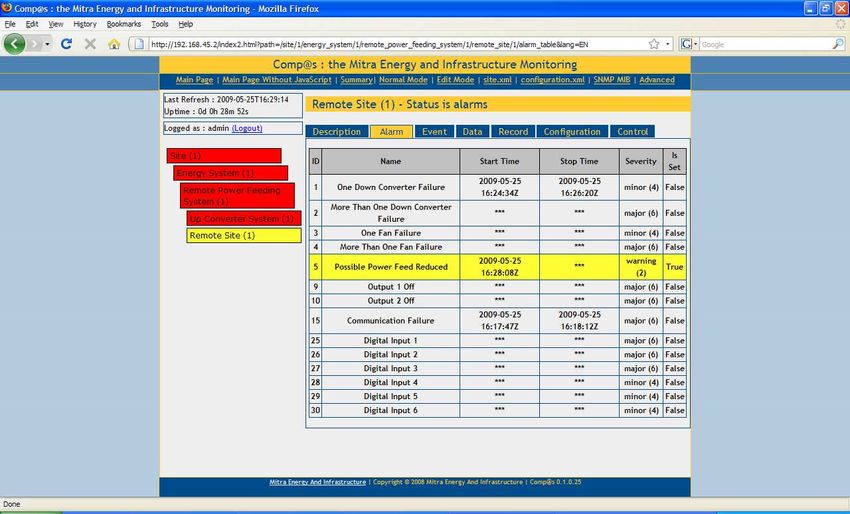
Table of Contents

1.  About this guide ...............................................................................................................3
2.  Module overview...............................................................................................................4
3.  Hardware installation ........................................................................................................5
  3.1   DIP switches..............................................................................................................5
    DIP switches on MCU Comp@s module...........................................................................5
    DIP switches on CEM03 monitoring module ....................................................................5
  3.2   Plug-in .......................................................................................................................6
  3.3   CAN bus wiring .........................................................................................................6
4. Communication.................................................................................................................7
  4.1   USB ...........................................................................................................................7
  4.2   Ethernet .....................................................................................................................8
5. Configuration ....................................................................................................................9
  5.1   Allocation of the Up-converter outputs......................................................................9
  5.2   Allocation of the monitoring inputs ..........................................................................10
  5.3   Save configuration...................................................................................................11
6. Description of screens....................................................................................................12
  6.1   Remote Power Feeding System menu ....................................................................12
  6.2   Up Converter System menu ....................................................................................14
  6.3   Remote Site menu ...................................................................................................17

                                                                   2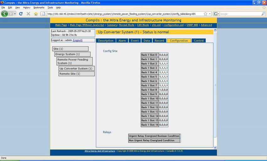
1.   About this guide

This guide describes the main steps to get started with the MCU Comp@s module for remote
powering (ref. 9413 060 00041).

For more details about the central up converter shelf, refer to CES48 Central Up Converter User
Guide (ref. 4804 872 5080x)

Guide history:

          Edition     Date       Page                    Changes
            010     20-05-2009    -     First edition
            020     08-03-2012    -     Second edition

                                                    3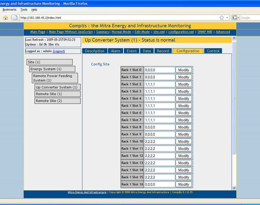
2.   Module overview

The MCU Comp@s module for remote powering is a card that allows you to supervise a network
made up of different central converters and remote sites.
This card is intended to be plugged in a CES48 remote powering central up converter shelf and can
be connected to other shelves via CAN bus.
The communication can be done locally or remotely via USB or Ethernet.

                                                                     USB port

                                                                    Ethernet port

                                                                    Card status LED: powered
                                                                    or not (blinking at start-up)

                                                                     Minor alarm LED: lighted if alarm

                                                                     Major alarm LED: lighted if alarm

                                                                     CAN ports: 2 ports in parallel

                                                                        DIP switch for CAN bus
                                                                          termination resistor

                                                                     Additional CAN port with DC
                                                                      supply to connect specific
                                                                               devices

                                                4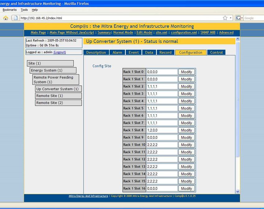
3.    Hardware installation

3.1   DIP switches
DIP switches need to be correctly configured before use.

DIP switches on MCU Comp@s module

        DIP switch 1 needs to be ON to connect the 120 ohm CAN bus termination resistor. DIP
        switches 2 and 3 are not used.

DIP switches on CEM03 monitoring module

        For each CEM03 module, DIP switches must be configured as follows:

                                                                        DIP 1: Slave or Master
                                                                        First card of each shelf must be Master
                                                                        Other cards must be Slave
                                                                        Maximum 4 cards per shelf

                                                                        DIP 2 to 5: Not used

                                                                        DIP 6: CAN bus used

                                                                        DIP 1 to 6: CAN node address of the card in
                                                                        binary*

                                                                        Master card address must be a multiple of 4
                                                                        (0, 4, 8, 12,...)

*
                                                                        Slave card address must be Master card
                                                                        address + 1, 2 or 3

*
 For information the real CAN node address is actually 100 – DIP address. To simplify we will use the term address to
designate the DIP address (address configured through the DIP switches)

                                                            5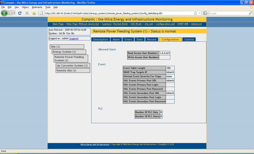
3.2   Plug-in
Plug the MCU Comp@s module in a free slot of the first CES48 central converter shelf.

3.3   CAN bus wiring
CAN bus ports of MCU Comp@s module and all CEM03 modules need to be daisy chained
together. For easy wiring, 2 connectors are foreseen on each module front face.

A termination resistor of 120Ω needs to be connected to the last module. The termination resistor of
the first module (MCU Comp@s module) is already present in the module (if DIP switch 1 is ON).

Example of wiring:

  Central up               C     M                                CEM03 : Master (address = 0)
  converter shelf #1       E     C
                           M     U
                           03

  Central up               C     C     C                           CEM03 #1: Master (address = 4)
  converter shelf #2       E     E     E                           CEM03 #2: Slave (address = 5)
                           M     M     M                           CEM03 #3: Slave (address = 6)
                           03    03    03
                           #1    #2    #3

  Central up               C                                        CEM03 : Master
  converter shelf n        E                                        (address = (n-1)*4)
                           M
                           03

                       120Ω resistor

                                                  6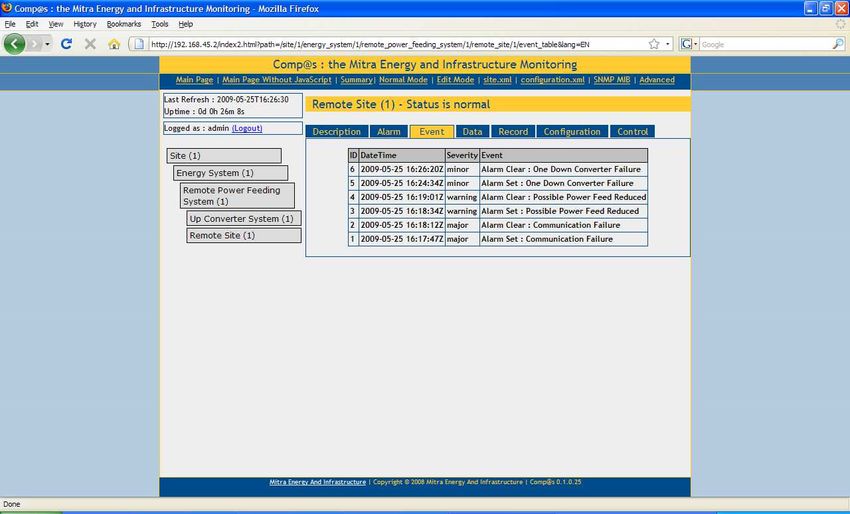
4.    Communication
The communication with the MCU Comp@s module can be done locally or remotely through 2
different ports: USB or Ethernet.

The following table shows an overview of the data needed:

                                  USB                  Ethernet                  Comment
                                                                        Internet Explorer 7.x or higher
      Software required       Web browser           Web Browser
                                                                             Firefox 2.x or higher

                          Microsoft Active Sync
                            application - free
                              Compas.reg                                  Registry modification file

        URL address          http://127.0.0.1     http://192.168.45.2

       User name – as
                                 admin                  admin                   case sensitive
        administrator

         Password               compas                 compas                   case sensitive

4.1   USB
The USB Type-B socket provides a standard USB client connection,
allowing having a local connection with any computer. Here follows the
procedure.

Required material:
       A personal computer with Ethernet capabilities;
       A standard Type-B plug to Type-A USB plug.

Required software:
       A Windows XP operating system;
       A web browser: it is recommended to use Firefox 2.x or Internet Explorer 7.x.
       The free Microsoft Active Sync application. This application is available on the web:
   http://www.microsoft.com/windowsmobile/activesync/activesync45.mspx

       STEP 1: Do not connect the USB cable yet

       STEP 2: Install the Active Sync application. A computer reboot may be asked at the end of
       the installation.

       STEP 3: Activate the port forwarding over USB. To do this, a small modification in the registry
       must be done. Open a new text file and write the followings 3 lines:

       Windows Registry Editor Version 5.00
       [HKEY_LOCAL_MACHINE\SOFTWARE\Microsoft\Windows CE Services\ProxyPorts]
       "HTTP PORT FORWARDING"=dword:00000050

       Remark: You can also use the windows registry editor “Regedit” to add the entry.

       STEP 4: Then, save the file as “Compas.reg” and execute it (double-click).

       STEP 5: Connect the USB cable between the personal computer and the Comp@s
       monitoring.

                                                   7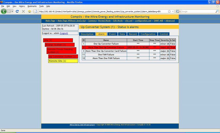
STEP 6: Active Sync application should detect the connection and ask to “Set Up a
       PartnerShip”. Just click on “No” and afterwards on “Next”.

       STEP 7: Start your Web Browser and browse the URL address http://127.0.0.1 or
       http://localhost .

       STEP 8: The Comp@s web server will ask for a login and a password which are:

                                        Login/User Name: admin
                                            Password: compas
                         (Please note that login and password are case sensitive)

       You are now connected on the web interface as administrator of the system.

4.2   Ethernet
The Comp@s monitoring RJ45 female port provides a standard 10/100 MBit Ethernet connection.
The default network configuration is:

                                        IP address: 192.168.45.2
                                        Sub Mask: 255.255.255.0

Required material:
   A personal computer with Ethernet capabilities;
   A crossed Ethernet cable if the PC is directly connected to the Comp@s monitoring (Some
   recent PC have an automatic polarity detection, in this case a straight cable can be used);
   A straight Ethernet cable if the Comp@s monitoring is connected to a switch.

Required software:
   Any operating system with an up to date web browser. It is recommended to use Firefox 2.x or
   Internet Explorer 7.x.

To connect to the system, the personnel computer has to be configured with a static IP address.
You can use the IP 192.168.45.1 for example, with 255.255.255.0 as sub mask.

To do this under Windows XP, Access the Network Connections control panel (Start
                                                                               Start   Control
Panel     Network Connections).
                  Connections Pick the connection you are using, generally Local Area
Connection. Right-click on that connection icon and pick Properties. Under "this connection uses the

                                                 8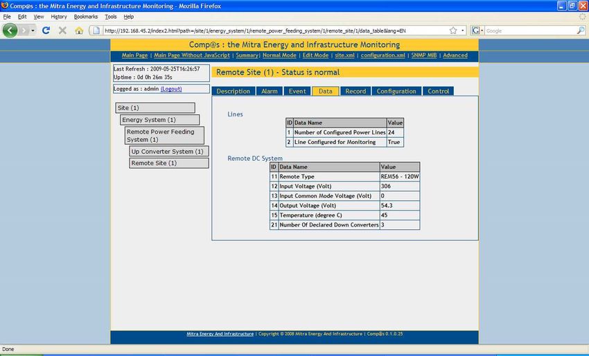
following items," scroll down to "Internet Protocol (TCP/IP)" and double-click on that. The "Internet
Protocol (TCP/IP) Properties" window will appear.

5.    Configuration

The Up-converter outputs and monitoring inputs need to be allocated to the different remote sites.

5.1   Allocation of the Up-converter outputs
Get connected to the MCU Comp@s module through your browser and follow the next procedure:
   Click on “Edit Mode”
   Click on “Configuration”
   For each UP converter shelf X:
          Click on Up Converter System (X)
          For each Up-converter, configure the site number and click on “Modify”

Here below is an example where the Up-converters of slots 2 to 7 are dedicated to site #1 and the
Up-converters of slots 10 to 15 are dedicated to site #2. The other slots are either not used or
populated with other cards (input card, CEM03 monitoring card, MCU Comp@s card or fan supply
card)

Note that slots 1 and 2 are reserved for the input module and slot 16 is reserved for the fan supply
module.

Each Up converter can be configured individually. For example for slot 2 you can dedicate the Up-
converters 1 and 2 to site 6 and the Up-converters 3 and 4 to site 7 by typing “6,6,7,7”

                                                   9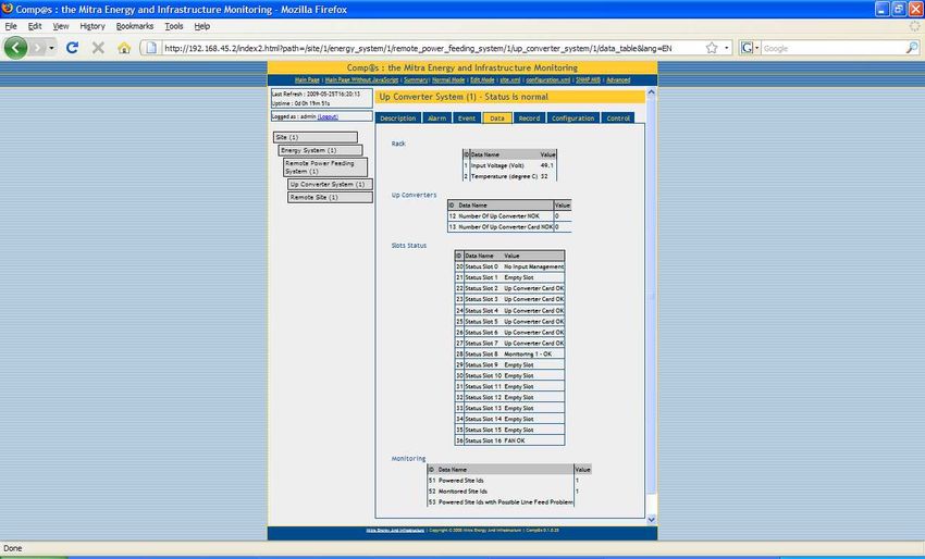
5.2    Allocation of the monitoring inputs
      Follow the next procedure:
      Click on “Edit Mode”
      Click on “Configuration”
      For each UP converter shelf X:
              Click on Up Converter System (X)
              For each CEM03 monitoring module communication input (R1, R2, R3 and R4), configure
              the site number and click on “Modify”

         Here below is an example where the CEM03 monitoring module is in slot 8. The
         communication input R1 is dedicated to site #1 and the communication input R2 dedicated to
         site #2. Communication inputs R3 and R4 are not used.

         Up to 4 CEM03 monitoring cards can be used per shelf (1 master card and 3 slave cards)
         allowing to monitor up to 16 remote sites.

                                                 10
5.3 Save configuration
After having allocated the different up-converters and monitoring inputs do not forget to save the
configuration! If you do not, the new settings will be lost once the MCU is switched off. In order to do
so:
Click on “Edit Mode”
Click on “Site (1)”
Click on “Control”
In front of “Save XML User Configuration” click on “Execute”
SAVE
116. Description of screens
This section describes the different screens available through the web browser. We will focus on the
screens that are specific to remote powering. For more details about the general functionalities refer
to the Magellan Comp@s Advanced User Guide (ref. 4804 872 5100x).
The screens shown below are from the “Normal Mode” menu. Note that some parameters can be
configured through the “Edit Mode” menu.
6.1 Remote Power Feeding System menu
This menu appears as soon as you connect a remote powering system to the MCU Comp@s card
through the CAN bus.
Description menu allows to configure a description and a reference for the remote power feeding
system:
12Data menu shows an overview of the system status:
Configuration menu allows configuring some system parameters. For more details, refer to
the Magellan Comp@s Advanced User Guide (ref. 4804 872 5100x).
13Control menu allows managing the events related to the system. Events can be cleared or
added:
6.2 Up Converter System menu
This menu appears as soon as you connect a CEM03 monitoring card to the MCU Comp@s card
through the CAN bus. One such menu will appear for each CEM03 module configured as Master
(i.e. one menu for each Central converter shelf).
Description menu allows configuring a description and a reference for the Up Converter System. It
also shows information about the corresponding CEM03 Master card.
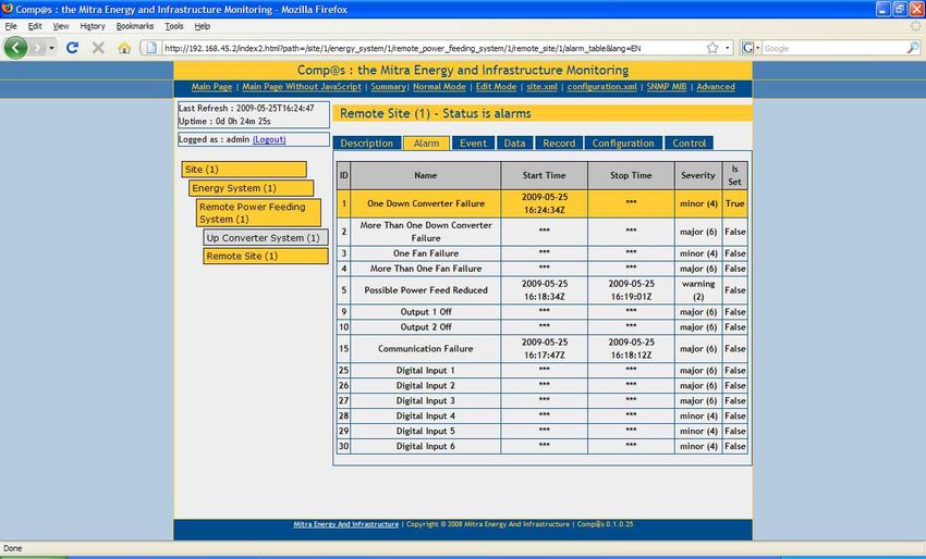
14Alarm menu shows the alarms at Central converter level: Up converter failures and shelf fan failures.
A major alarm will be highlighted in red. A minor alarm will be highlighted in orange. A warning will
be highlighted in yellow.
The two following snapshots show an example where several up converters card from the shelf are
in failure. This generates a major alarm at “Up Converter System (1)” level and a warning at “Remote
Site (1)” level. This last warning alarm is a “Possible Power Feed Reduced” that warns you that
available power might be reduced at remote site.
15Event menu lists the events (for example alarms) appeared through the system life time:
Data menu gives information about the Central up-converter shelf:
Note that the MCU Comp@s card itself does not appear in the slot status table.
16Configuration menu allows allocating the up converters and monitoring inputs to the remote sites. It
is also possible to control the dry contact relays of the shelf. Note that by default the urgent relay is
dedicated to major alarm and the non-urgent relay is dedicated to minor alarm.
6.3 Remote Site menu
This menu appears as soon as a remote site is configured through the “Up Converter System”
configuration menu. One such menu will appear for each remote site configured.
Description menu allows to add general information about the remote site:
17Alarm menu shows the alarms at remote site level. Note that “Output 2 Off” alarm is not used
for remote systems with only one output.
Event menu lists the events (for example alarms) that have appeared through the system life
time:
18Data menu gives information about the remote site shelves:
Configuration menu allows assigning a name to the remote site digital inputs (remote site
external alarms):
19Alpha Technologies S.A.
131, Boulevard de l’Europe
B1301 Wavre
BelgiumYou can also read