Analysis of Elliptical Wing Type Bird Inspired Device
←
→
Page content transcription
If your browser does not render page correctly, please read the page content below

IOP Conference Series: Materials Science and Engineering

PAPER • OPEN ACCESS

Analysis of Elliptical Wing Type Bird Inspired Device
To cite this article: M H Kumar and P Dorlikar 2021 IOP Conf. Ser.: Mater. Sci. Eng. 1116 012147

View the article online for updates and enhancements.

 This content was downloaded from IP address 46.4.80.155 on 26/08/2021 at 19:53
FSAET 2020 IOP Publishing
IOP Conf. Series: Materials Science and Engineering 1116 (2021) 012147 doi:10.1088/1757-899X/1116/1/012147

Analysis of Elliptical Wing Type Bird Inspired Device

 M H Kumar1 and P Dorlikar2
 1
 PG Student, Mechanical Engineering, Army Institute of Technology, Pune, India
 2
 Assistant Professor, Mechanical Engineering Department, Army Institute of
 Technology, Pune, India

 Email: maharshi_161019@aitpune.edu.in

 Abstract. Technology advancements have made the use of Unmanned Aerial Vehicles (UAV)
 in many applications. This paper aims at performing stress analysis of elliptical wing type birds
 using ABAQUS. The wings considered for investigation are elliptical wings of two birds having
 low aspect ratio. Aerodynamic forces like lift and drag are calculated and applied on proposed
 wing design CAD models to obtain results of stresses and structural deformation at different
 altitude. The material used for wing structure is carbon fiber for its various advantages over other
 materials. Further, shape optimization of wing structure has performed to reduce the stresses at
 critical regions and to reduce volume of material. This wing design analysis helps designers to
 build UAV in optimizing manner. In addition to above investigation, various flapping wing
 mechanisms 2D in SAM and 3D in ADAMS have made based on curves that are obtained by
 tracing the tip of wings of selected birds in TRACKER.

 Keywords: Unmanned Aerial Vehicle, Elliptical Wing, Shape Optimization, Flapping Wing
 Mechanism.

1. Introduction
Mimicking of birds flight can be obtained by various flapping wing mechanism. Technology has been
advanced towards development of UAV’s for its various applications form photography to ground
inspection because of its portable nature [1]. Robust designs of flapping wings have made with the
carbon fiber as light weight material for the analysis of wings at different altitudes by calculating
aerodynamic forces [2]. Various optimization parameters are considered while predicting wing
kinematics [3]. The dynamic analysis of wing provides useful information such as natural frequencies,
damping properties and mode shapes of wings [5]. Study on flapping wing mechanism was performed
for optimization of drag and lift force [4]. There is limitation to which the wing structure can sustain the
maximum stresses and one of this limitation is eliminated by optimization of wing structure. The study
in this paper is to determine stresses due to aerodynamic forces on wing designed structure and realizes
how shape optimization analysis becomes more important as it reduces maximum stresses and also
spatial displacement.

2. Mechanism of Flapping Wing
The calculation of lift and drag force is discussed in later section. The driving mechanism for flapping
wing is given in the figure 2.1. The stagger angle is denoted by γ. Crank length is given by l1. Linkage
length is denoted by l2. Rocker length is denoted by l3. Angle between the crank and OO1 is denoted by
α.

 Content from this work may be used under the terms of the Creative Commons Attribution 3.0 licence. Any further distribution
 of this work must maintain attribution to the author(s) and the title of the work, journal citation and DOI.
Published under licence by IOP Publishing Ltd 1
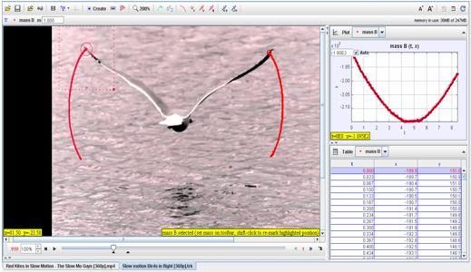
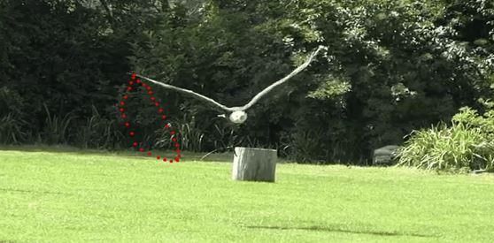
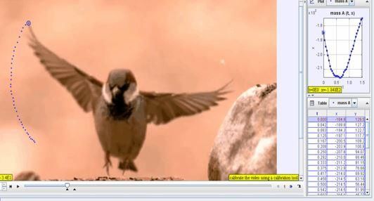
FSAET 2020 IOP Publishing
IOP Conf. Series: Materials Science and Engineering 1116 (2021) 012147 doi:10.1088/1757-899X/1116/1/012147

Figure 2.1. Flapping wing driving mechanism. Figure 2.2. Four bar mechanism.

Four bar mechanism has been developed by Freudenstein as shown in Fig. 2.2. An analytical approach
has been also developed by Freudenstein. The frame is made to unity and the lengths of other links are
denoted by a, b and c and the input and output angle are denoted by θ2 and θ4. Freudenstein obtained a
simple scalar equation.

 cos(θ2 – θ4) = K1cos θ4 – K2cos θ2 + K3 (1)

 K1 = d/a (2)

 K2 = d/c (3)

 K3 = (a2 - b2 + c2 + d2) / (2ac) (4)

The above equation is called Freudenstein Equation. The above equation can be applied for the
kinematic synthesis of four bar mechanisms.

3. Curves obtained in different Software

3.1. Bird Wing Tip Curves obtained in TRACKER
Elliptical wing type birds such as sparrow and pigeon videos during their flight motion were analysed
in TRACKER to determine different wing tip curves as show in Fig. 3.1.

 2
FSAET 2020 IOP Publishing
IOP Conf. Series: Materials Science and Engineering 1116 (2021) 012147 doi:10.1088/1757-899X/1116/1/012147

 Figure 3.1. Different wing tip curves obtained in TRACKER.

3.2. Different 2D Flapping Mechanisms and their Curves obtained in SAM
The different wing tip curves obtained in TRACKER is useful for building different 2D flapping
mechanisms in SAM.

 3
FSAET 2020 IOP Publishing
IOP Conf. Series: Materials Science and Engineering 1116 (2021) 012147 doi:10.1088/1757-899X/1116/1/012147

 Figure 3.2. Different 2D flapping mechanisms in SAM.

 4
FSAET 2020 IOP Publishing
IOP Conf. Series: Materials Science and Engineering 1116 (2021) 012147 doi:10.1088/1757-899X/1116/1/012147

3.3. Different 3D Flapping Mechanisms in ADAMS
Different 3D flapping mechanisms are made in ADAMS for simulation purposes.

 Figure 3.3. Different 3D flapping mechanisms in ADAMS.

4. Selection of Wing Material
Selection of wing material is important factor from aerodynamic forces point of view. The material
selected is carbon fiber which has following material properties as listed below:
Modulus of Elasticity, E = 135 Gpa, Density, ρ = 1600 Kg/m3, Ultimate compressive strength σc =
1200 Mpa, Ultimate tensile strength σt = 1500 Mpa, Shear Modulus = 5 Gpa and Poisson’s ratio = 0.3.

 5
FSAET 2020 IOP Publishing
IOP Conf. Series: Materials Science and Engineering 1116 (2021) 012147 doi:10.1088/1757-899X/1116/1/012147

5. Shape of Bird Wing
The birds considered for investigation are elliptical wing type of birds. They have low aspect ratio, tight
maneuvering, fast take offs and high speed for short period of time. Few examples are wood pigeon,
hooded crow, raven, blackbird, pheasant, and sparrows. For analysis, two birds, wood pigeon and
hooded crow are considered.

6. CAD Design of Wing Structure
Proposed design of wing structure of wood pigeon and hooded crow are shown in Figure 6 (a), (b), (c)
and (d). The wing structure of wood pigeon has wing span of 0.751 m in x direction and 0.187 m in y
direction. The wing structure of hooded crow has wing span of 0.925 m in x direction and 0.19 m in y
direction. The weight of designed wing structure of wood pigeon is 388.76 g and weight of designed
wing structure of hooded crow is 562.4 g.

 Figure 6. (a). Wood Pigeon. Figure 6. (b). Wood Pigeon wing structure design.

 Figure 6. (c). Hooded Crow. Figure 6. (d). Hooded Crow wing structure design.

6.1. Lift and Drag Calculations
Considering the flight to be 2D (motion in x and y direction), the values for drag and lift are calculated
using following equations:

 Fx,0 = (½) CD ρ A V2 (5)

 Fy,0 = (½) CL ρ A V2 (6)

and
 V = √ 2 + 2 (7)

 6
FSAET 2020 IOP Publishing
IOP Conf. Series: Materials Science and Engineering 1116 (2021) 012147 doi:10.1088/1757-899X/1116/1/012147

Fx,0 is Drag Force, Fy,0 is Lift Force, CD and CL are Coefficients of Drag and Lift respectively, velocity
of wind is given by V, Density of air is given by ρ, Velocity in forward direction (x direction) is given
by Vx and velocity in y direction is given by Vy, wing area is given by A. The density of air changes
with altitude and hence the aerodynamic forces lift and drag also changes. The variation of density with
altitude is given in table 1.

 Table 1. Density variation with altitude [2].

 Sl. No. Altitude Density (Kg/m3)
 (m)
 1. 60 1.215

 2. 500 1.165

 Table 2. Wing specifications for elliptical wing type birds [1].

 Sl. Bird Name Category Mass Span Area (m2) Velocity Wingbeat
 No. (kg) (m) (m/s) Frequency
 (Hz)

 1. Wood Pigeon Elliptical wing 0.495 0.751 0.0797 15.4 5.61
 (Low Aspect Ratio)

 2. Hooded Crow Elliptical wing (Low 0.553 0.925 0.147 10.5 3.84
 Aspect Ratio)

The data for wingbeat frequencies and speeds of birds are calculated by Pennycuick [1] and are given
in table 2. The calculated values of lift and drag forces are given in table 3. The values are obtained from
the equations (5) and (6).

 Table 3. Calculated values of lift and drag with varying altitude.

 Sl. Bird Name Altitude Density Drag (N) Lift (N)
 No. (m) (kg/m3)
 1. Wood Pigeon 60 1.215 0.332 2.974

 2. Wood Pigeon 500 1.165 0.319 2.851

 3. Hooded Crow 60 1.215 0.285 2.550

 4. Hooded Crow 500 1.165 0.273 2.445

 7
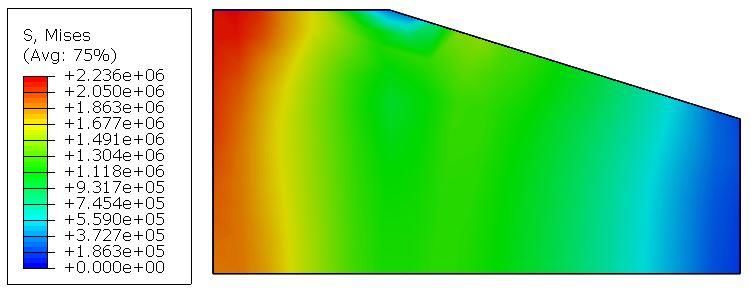
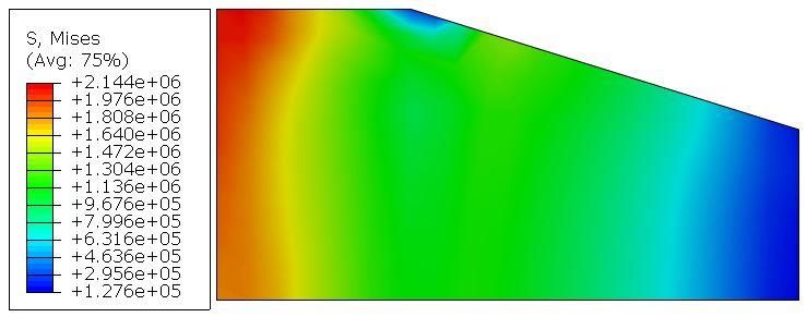
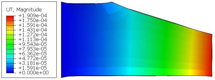
FSAET 2020 IOP Publishing
IOP Conf. Series: Materials Science and Engineering 1116 (2021) 012147 doi:10.1088/1757-899X/1116/1/012147

7. Modelling in ABAQUS
The CAD model of wing structure is modelled in ABAQUS having material properties of carbon fibre.
The procedure used for analysis is General-Dynamic Explicit. Concentrated forces on designed wing
structures have been applied to obtain stresses and spatial displacements. The thickness for wing
structure in both the cases of design are taken to be 4 mm. The base of the wing is fixed to the main
body structure and therefore fixed boundary conditions are applied defined as ENCASTRE in which all
the six degrees of freedom (U1= U2 = U3 = UR1 = UR2 = UR3 = 0) have given zero value.

8. Results Without Optimization and With Shape Optimization

8.1. Without Optimization of Wing Structure
Stress and Displacement results of wood pigeon for altitude of 60 m and 500 m are as shown in Fig.
8.1. (a), (b), (c) and (d).

Figure 8.1. (a). Stress at altitude of 60 m Figure 8.1 (b). Spatial displacement at altitude
 of 60 m

Figure 8.1. (c) Stress at altitude of 500 m Figure 8.1. (d). Spatial displacement at altitude of
 500 m

Stress and displacement results of hooded crow for altitude of 60 m and 500 m are as shown in Figure
8.1. (e), (f), (g) and (h).

 8
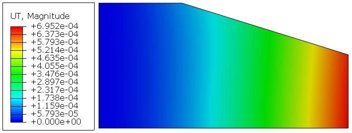
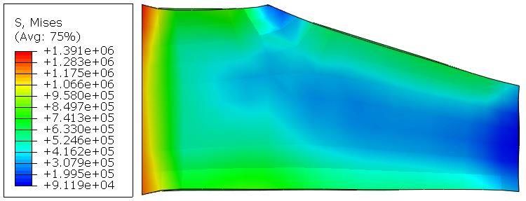
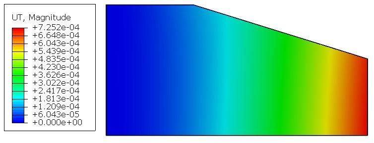
FSAET 2020 IOP Publishing
IOP Conf. Series: Materials Science and Engineering 1116 (2021) 012147 doi:10.1088/1757-899X/1116/1/012147

Figure 8.1 (e) Stress at altitude of 60 m Figure 8.1 (f). Spatial displacement at altitude of
 60 m

 Figure 8.1 (g). Stress at altitude of 500 m Figure 8.1 (h). Spatial displacement at altitude
 of 500 m

 Table 4. Maximum stress and displacements at varying altitudes

 Sl. No. Bird Name Altitude Maximum Wing Stress Maximum Spatial
 (m) (KPa) Displacement (m)

 1. Wood Pigeon 60 2236 0.00072

 2. Wood Pigeon 500 2144 0.00069

 3. Hooded Crow 60 17.66 0.0041

 4. Hooded Crow 500 17.910 0.0043

8.2. With Shape Optimization for Wing Structure of Wood Pigeon at Altitude of 500 m
To reduce the maximum stress at critical regions and spatial displacements, shape optimization of wing
structure in ABAQUS has performed.

 Figure 8.2. (a). Stress at altitude of 500 m Figure 8.2. (b). Spatial displacement at altitude
 of 500 m

 9
FSAET 2020 IOP Publishing
IOP Conf. Series: Materials Science and Engineering 1116 (2021) 012147 doi:10.1088/1757-899X/1116/1/012147

8.3. Comparison between Stresses and Displacements of Wing Structure Design With and Without Shape
Optimization of Wood Pigeon Wing Structure at an Altitude of 500 m
Below table shows clearly how shape optimization can help designers to reduce maximum stress and
spatial displacement in order to mimic the flight as accurately as possible.

 Table 5. Analysis comparison with and without shape optimization.
 Sl. Analysis Type Altitude (m) Maximum Wing Maximum Spatial
 No. Stress (KPa) Displacement (m)
 1. With 500 1391 0.00019
 Optimization
 2. Without 500 2144 0.00069
 Optimization

Below figure shows the comparison between stresses of wing structure design with shape optimization
and without optimization.

Figure 8.3. (a). Stress at altitude of 500 m with Figure 8.2. (a). Stress at altitude of 500 m without
 with shape optimization without optimization

9. Conclusions
In this paper, two birds having elliptical wings of low aspect ratio are considered for calculation of
aerodynamic forces and its effect on proposed design of wing structure is examined with variation in
altitude. It is observed from the stress results that, compared to wood pigeon wing structure design, the
stresses are less on hooded crow wing structure design. It is worth to be noted that with the help of shape
optimization the maximum stresses are further reduced to 35% of initial maximum stress in the case of
wood pigeon wing structure at an altitude of 500 m. Hence, shape optimization analysis proves to be
effective method to reduce maximum stresses.

References
[1] Pennycuick C J 2001 Speeds and Wingbeat frequencies of Migrating Birds compared with
 calculated Benchmark Journal of Experimental Biology 204 3283–94
[2] Goel M D and Rawat U 2017 11th International Symposium on Plasticity and Impact Mechanics,
 Implast Elsevier Design and analysis of wing structures of micro air vehicles 173 1602-10
[3] B Parslew 2012 University of Manchester Engineering and Physical Sciences Simulating avian
 wingbeats and wakes PhD. Thesis
[4] George and Brandon R 2011 All Theses and Dissertations Design and analysis of a flapping wing
 mechanism for optimization 2737

 10
FSAET 2020 IOP Publishing
IOP Conf. Series: Materials Science and Engineering 1116 (2021) 012147 doi:10.1088/1757-899X/1116/1/012147

[5] Kumar D, Shah M, Mohite P M, Kamle M 2014 International Journal of Recent advances in
 Mechanical Engineering Structural dynamic analysis of bioinspired carbon
 fiber/ployethylene MAV wings 3 4

 11
You can also read