Life cycle assessment on a passenger's airbag at Volvo cars
←
→
Page content transcription
If your browser does not render page correctly, please read the page content below

Life cycle assessment on a
passenger’s airbag at Volvo cars
Master’s thesis in Industrial Ecology

LORENA HUBER

DEPARTMENT OF TECHNOLOGY MANAGEMENT AND ECONOMICS
DIVISION OF ENVIRONMENTAL SYSTEMS ANALYSIS

CHALMERS UNIVERSITY OF TECHNOLOGY
Gothenburg, Sweden 2022
www.chalmers.se
Report No. E2022:051
REPORT NO. E 2022:051

Life cycle assessment on a passenger’s
           airbag at Volvo cars

               LORENA I. HUBER

    Department of Technology Management and Economics
         Division of Environmental Systems Analysis
       CHALMERS UNIVERSITY OF TECHNOLOGY
                  Gothenburg, Sweden 2022
Life cycle assessment on a passenger’s airbag at Volvo cars
LORENA I. HUBER

© LORENA I. HUBER, 2022.

Report no. E2022:051
Department of Technology Management and Economics
Chalmers University of Technology
SE-412 96 Göteborg
Sweden
Telephone + 46 (0)31-772 1000

Gothenburg, Sweden 2022
Life cycle assessment on a passenger’s airbag at Volvo cars

LORENA I. HUBER

Department of Technology Management and Economics
Chalmers University of Technology

SUMMARY

Environmental concerns have received considerable attention in recent decades, and there is
a greater understanding of how human activities affect and degrade the environment.
In recent decades, transportation systems have been one of the major contributors to poor air
quality, noise, and climate change. It is also well known that the automotive sector confronts
major environmental challenges not only for fuel consumption in terms of emissions during
usage but also during manufacturing processes.
Due to the importance of both safety and sustainability standards, Volvo Cars is concerned
about reducing the environmental impact of its products. A life cycle assessment (LCA) can
help them gain a better understanding of the environmental performance of some of their
products.
The aim of the study was to analyse, assess and provide relevant information regarding the
environmental performance of a car airbag during its manufacturing process, with this objective,
an LCA has been performed from cradle to gate for each of the ingoing parts of a passenger
airbag.
The study demonstrated that the bag, inflator and housing of the airbag were the components
that contributed most to the environmental impact. The selected impact categories were climate
impact, depletion of abiotic resources and freshwater consumption. More specifically, the
production and use of plastics such polyamide-6,6 (PA-6,6) and polypropylene, and other
materials such as steel and glass fibre production contributed significantly.
Some improvements with the objective of minimizing these impacts may be implemented based
on the findings of this LCA study. Increasing the recycling content of materials like plastic and
steel could be very advantageous, but this is only achievable when the recycling content
exceeds 50%.

Keywords: Life cycle assessment, airbag, carbon footprint, water use, resource depletion.
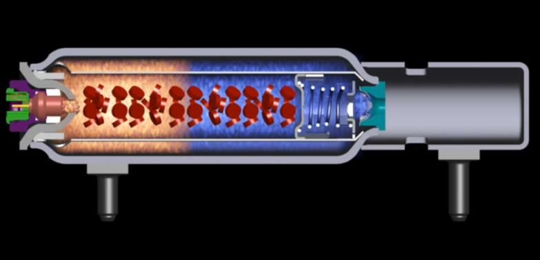
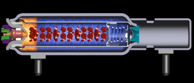
Table of Contents
Table of figures ................................................................................................................2
List of abbreviation ...........................................................................................................4
1 Introduction ..................................................................................................................5
   1.1 Background ....................................................................................................................... 5
2 Theory and literature review ..........................................................................................6
   2.1 Life Cycle assessment ........................................................................................................ 6
   2.2 Literature review .............................................................................................................. 7
3 Goal and scope definition...............................................................................................9
   3.1 Goal of the study ............................................................................................................... 9
      Research questions: ........................................................................................................................................9
      The reason of this study ..................................................................................................................................9
   3.2 Scope of the study............................................................................................................ 10
      Product description .......................................................................................................................................10
      Functional unit ..............................................................................................................................................12
      System boundaries ........................................................................................................................................12
      Choice of the impacts categories and method for impact assessment ..........................................................13
      Data collection ..............................................................................................................................................13
      Assumptions .................................................................................................................................................14
      Limitations ....................................................................................................................................................14

4 Inventory analysis ........................................................................................................14
   Technical description of the processes and components ........................................................ 15
   4.1 Bag .................................................................................................................................. 15
      Bag flowchart ...............................................................................................................................................16
      Raw materials and their manufacturing........................................................................................................16
      Bag’s manufacturing ....................................................................................................................................17
   4.2 Inflator ............................................................................................................................ 17
      Inflator Flowchart .........................................................................................................................................19
      Steel manufacturing ......................................................................................................................................19
      Gases (oxygen, argon, helium) .....................................................................................................................20
      Pyrotechnics .................................................................................................................................................20
      Rubber ..........................................................................................................................................................20
      Assembly of the inflator ...............................................................................................................................20
   4.3 Housing ........................................................................................................................... 21
      Polypropylene production ............................................................................................................................21
      Glass fibre production ..................................................................................................................................21
      Housing flowchart ........................................................................................................................................22
   4.4 Bushings .......................................................................................................................... 22
      Bushing flowchart ........................................................................................................................................23
   4.5 Label ............................................................................................................................... 23
      Label flowchart .............................................................................................................................................24
   4.6 Sealing cap ...................................................................................................................... 24

                                                                                                                                                                      1
Sealing cap flowchart ...................................................................................................................................25
   4.7 Wire Harness .................................................................................................................. 25
       Copper parts..................................................................................................................................................25
       Wire harness flowchart .................................................................................................................................26
   4.8 Airbag Assembly ............................................................................................................. 27
5 Results and Discussion ................................................................................................27
   Life cycle Impact assessment ................................................................................................ 27
   5.1 Dominance analysis ......................................................................................................... 27
       Global warming ............................................................................................................................................27
       Resources depletion ......................................................................................................................................30
       Freshwater consumption ...............................................................................................................................31
   5.2 Sensitivity Analysis.......................................................................................................... 33
       Distance ........................................................................................................................................................33
       Copper ..........................................................................................................................................................34
       Pyrotechnics .................................................................................................................................................34
       Polypropylene ...............................................................................................................................................34
       Glass Fiber ....................................................................................................................................................35
   5.3 Improvements scenarios .................................................................................................. 36
       Scenario for recycled plastic.........................................................................................................................36
       Scenario for recycled steel............................................................................................................................38
       Scenario for alternative material...................................................................................................................40

6 Conclusion ..................................................................................................................42
Bibliography ..................................................................................................................44
Appendix A ....................................................................................................................47
Appendix B ....................................................................................................................48

Table of figures
Figure 1 Final Energy consumption by sector, EU-28-2017 (16) ............................................. 6
Figure 2 General methodology framework for LCA (ISO 14040) ............................................ 7
Figure 3 Passenger airbag front side installed in the car’s dashboard ..................................... 10
Figure 4 Main components of a passenger airbag ................................................................... 11
Figure 5 General flowchart for the airbag production. ........................................................... 12
Figure 6 Driver’s airbag fully deployed (Euroncap, 2022)..................................................... 15
Figure 7 Passenger and driver’s airbag fully deployed (Euroncap, 2022) .............................. 15
Figure 8 Flowchart for the manufacturing of the bag .............................................................. 16
Figure 9 Inflator filed with gases and propellant ................................................................... 17
Figure 10: signal and ignition .................................................................................................. 18
Figure 11: the ignition of the propellants causes temperature and pressure increase .............. 18
Figure 12: the gases release ..................................................................................................... 18
Figure 13 Flowchart for the manufacturing of the inflator ..................................................... 19
Figure 14 Flowchart for the manufacturing of the housing ..................................................... 22

                                                                                                                                                                       2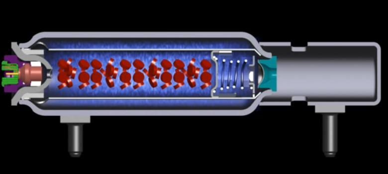
Figure 15 Flowchart for the manufacturing of the bushings.................................................... 23
Figure 16 Flowchart for the manufacturing of the label ......................................................... 24
Figure 17 Flowchart for the manufacturing of the sealing cap ................................................ 25
Figure 18 flowchart for the manufacturing of the wire harness .............................................. 26
Figure 19 Impact assessment category GWP for the manufacturing of the airbag module
(PAB) ....................................................................................................................................... 28
Figure 20 Shows airbag’s components and materials that have the greatest environmental
impact regarding to Global Warming Potential (GWP) .......................................................... 29
Figure 21 Impact assessment result for ADP for the life cycle of the airbag module “cradle to
gate” ......................................................................................................................................... 30
Figure 22 Shows airbag’s components and materials that the greatest environmental impact
regarding to ADP ..................................................................................................................... 31
Figure 23 Shows the impact assessment for freshwater consumption category for the
manufacturing of the complete airbag module and its components ........................................ 32
Figure 24 Shows airbag’s components and materials that have the greatest environmental
impact regarding to freshwater consumption ........................................................................... 33
Figure 25 Sensitivity analysis for two data sets for polypropylene production with respect to
ADP for the housing production and its influence in the results for the airbag module (PAB)
production. ............................................................................................................................... 34
Figure 26 Sensitivity analysis for two data sets for polypropylene’s production with respect
to freshwater consumption ....................................................................................................... 35
Figure 27 Sensitivity analysis for two data sets for glass fibres with respect to abiotic
resources depletion................................................................................................................... 35
Figure 28 Sensitivity analysis for two data sets for glass fibres with respect to freshwater
consumption ............................................................................................................................. 36
Figure 29 Scenario for recycled plastic with different recycled contend in % with respect to
GWP ......................................................................................................................................... 37
Figure 30 Scenario for recycled plastic with different recycled content in % with respect to
abiotic resources depletion ....................................................................................................... 37
Figure 31 Scenario for recycled plastic with different recycled content in % with respect to
freshwater consumption ........................................................................................................... 38
Figure 32 Scenario for recycled steel with different recycled contend in % with respect to
GWP ......................................................................................................................................... 39
Figure 33 Carbon footprint scenario for 30% recycled plastic and 25% recycled steel in
comparison with the base scenario .......................................................................................... 39
Figure 34 Comparison between polyamide 6.6 and PET for the manufacturing of the airbag
and the bag with respect to GWP ............................................................................................. 40
Figure 35 Comparison between polyamide 6.6 and PET for the manufacturing of the airbag
and bag with respect to Abiotic resources depletion. .............................................................. 40
Figure 36 Comparison between polyamide 6.6 and PET for the bag manufacturing and the
airbag production with respect to freshwater consumption. ................................................... 41

                                                                                                                                                3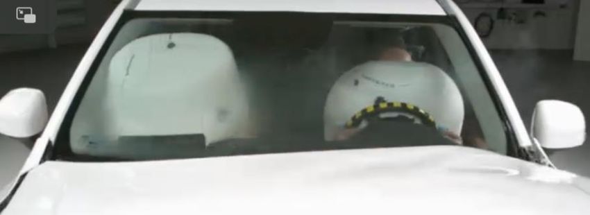
List of abbreviation
ADP Abiotic Resources depletion

CLM 2001is an impact assessment method

DMT Dimethyl terephthalate

Dtex: Decitex: Decitex is the count grading for filament and spinning yarns

ECU electronic control unit

GWP global warming potential

ISO: international standard organisation

LCA life cycle assessment

LCIA life cycle impact assessment

PAB Passenger airbag

Midpoint indicator: during the impact assessment phase, this indicator concentrates on a
single environmental problem such as global warming, ecotoxicity etc.

Endpoint indicator: during the impact assessment phase, show the environmental impact on
three higher aggregation levels, 1) effect on human health, 2) biodiversity and 3) resource
scarcity.

                                                                                              4
1 Introduction
In 1987 the United Nations Brundtland Commission defined sustainability as “meeting the
needs of the present without compromising the ability of future generations to meet their own
needs” (United Nations, 2022). The world population today is 7.8 billion people, and it is
expected by 2050 the population will be 9.9 billion people (PBR, 2020). Therefore, the current
generation has the ethical responsibility to confront today’s environmental challenges and
ensure to leave enough resources for future generations.
During the last decades, environmental problems have gained more and more attention, and
there is more awareness about how human activities have affected and caused damages to the
environment. The amount of carbon dioxide and other gases emitted by human activities have
been increasing drastically since the Industrial Revolution (BBC, 2013).
Anthropocentric activities such as burning of fossil fuels, deforestation for agriculture and
grazing livestock have contributed not only to global warming but also have caused other
damages to the environment (Europeiska kommissionen, 2022). The unbalance in the
greenhouse gases has tremendous consequences on the planet’s weather, the climate system,
and on the planet’s biodiversity (Nunez, National geographic, 2019)
While material and energy are essential for human survival, it is also true that the
consumption of these resources has increased enormously in recent decades, to the point of
over consumption. The challenge today is how to cover the needs in products and services for
9 billion people in the near future, that is why it is necessary the consumption needs to be
steered in a more sustainable direction so it will not harm the planet. Scientists in different
fields are responsible for improving or developing new technologies, finding new materials,
new energy sources and recycling processes to make better use of the planet’s resources.
1.1 Background
It is known that the automotive sector encounters significant environmental challenges not
only when it comes to fuel consumption, with respect to emissions during the user phase
because of the combustion of fossil fuels, but also during the manufacturing processes. During
the last decades, the transportation systems has become one of the largest contributors to poor
air quality, noise pollution and climate change (Nunez, National geographic, 2019) (European
Environmental Agency, 2022)
The transport sector consumes 30,8% of the total energy consumption in Europe (Eurostat,
2019), and it is among the most significant sources of greenhouse gas emissions, producing
around 15% of the total European carbon dioxide emissions (figure 1) (European Commission,
2011). The reduction of emissions in the transport sector is one of main policy goals in Europe,
looking for more sustainable technology in the sector (European Environmental Agency, 2020)
5Figure 1 Final Energy consumption by sector, EU-28-2017 (16)
Volvo Cars is a multinational manufacturing corporation headquartered in Gothenburg,
Sweden, the company is conscious of being responsible and acts to meet not only safety
standards, but also sustainability standards in terms of minimising the impact that its products
may have on the environment. The company aims to reach carbon neutrality by 2040 (Volvo
Car Corporation, 2022), and in order to support this commitment, the company plans to reduce
their carbon footprint in its products (Sustainability Centre Volvo Cars, 2021).With the help of
life cycle assessment, they can have a deep understanding of the environmental performance
of some of their products.
2 Theory and literature review
2.1 Life Cycle assessment
Life cycle assessment is a method to assess the environmental impact of a product or a
service across its life cycle. A life cycle assessment (LCA) follows a product from its extraction
as raw material, through production and use until its disposal (Baumann & Tillman, 2004). The
method provides a holistic view of the life cycle of a product rather than information about
separated processes.
6Figure 2 General methodology framework for LCA (ISO 14040)
The master thesis has followed the steps described below in the performance of the Life
cycle assessment: (ISO 14040, 2022)
• Goal and scope definition: in the first step the specification of the product, the intent
application and the purpose or reason of the study is determined as well as the system
boundaries are defined.
• Inventory analysis: in this second step, the model is constructed based on the boundaries
that were defined in the first step.
• Impact assessment (LCIA): indicates the impacts of the environmental loads described
and quantified in the inventory analysis.
• Interpretation of the results.
2.2 Literature review
The following chapter presents a selection of research papers about alternative materials for
airbag components such as the bag and the housing and a LCA study on a driver’s airbag.
Mujiyanto and Priyojati (2010), in their thesis, have studied the environmental
performance of a pyrotechnical driver’s airbag “cradle to grave”. They have focused on
environmental impacts such as Global warming potential, Acidification, Eutrophication,
Resource Depletion, Aquatic Ecotoxicity and Human Toxicity. The results showed that
processes that have larger impact on the environment in the whole life cycle of the driver’s
airbag are steel and polyamide productions and the entire life cycle for one airbag produced
4,93 kg waste, consumed 569 MJ, and required 79 kg water (Mujiyanto &Priyojati, 2010).
Many of the research papers that examined alternative materials for the airbag’s bag
suggested PET plastic as a good alternative material.
7Guifen Yao (2015), in his article explains that polyamide 6.6 has always been the most
traditional material for airbag fabrics, it is a material that meets the requirements for the
fabrication of airbags, but polyester filament demonstrated similar characteristics in terms of
mechanical and thermal properties, and it can be considered an equivalent material as
polyamide 6.6 (Guifen, 2015).
Nyström and Olsson (2013), in their thesis, have investigated the possibility of using
alternative materials for the fabrication of airbag’s cushions. The objective was to understand
different characteristics of textile materials and study the possibility to change materials in the
fabrication of airbag’s cushions and with optimise cost. The results showed that one of the
samples of PET tested could be used as material for bag’s fabrics (Nyström & Olsson, 2013).
Orme et al. (2014), have made a comparative study about the use of PET in place of
polyamide 6.6 for airbag’s cushions. They affirm that PET and polyamide 6.6 are materials
that present differences, but improvements in PET have made the material attractive to use as
cushions fabrics. They concluded that PET can be a suitable material for the fabrication of
airbag's cushions in certain conditions, for example, if design modifications are made so that
the product meets the necessary requirements.
Alternative materials for housing’s production were also examined throughout the
literature review. Because of its light weight and other characteristics, some studies suggested
using magnesium in various components of a vehicle, as for example for airbag’s housing.
(Orme, Walsh, & Westoby, 2014).
Yang Jin et al. (2000), propose in their research, the possibility of using magnesium alloy
in the fabrication of passenger airbag’s housings. They have compared different alternative
materials for plastic’s housings in terms of weight, and it has been shown that magnesium is
much lighter and the fabrication of magnesium housing results in considerable weight savings.
They conclude that die-cast magnesium alloy offers a greater degree of design freedom, and
that magnesium is an optimal option for passenger airbag’s housing, saving approximately 1
kg in weight. These findings are advantageous when considering current environmental
regulations and the increased demand for fuel-efficient lightweight vehicles. (Yang, Ko, Lim,
Hyun, & Lee, 2000).
Kumar et al (2000), explain the advantages of using magnesium alloys as material in
automotive and in aerospace due to the increased interest for lightweight materials. In their
study, they explain the connection between the use of light materials in vehicles and the
reduction in the carbon footprint. (Kumar, Phanden, & Thakur, 2021)
On the contrary, Witik et al. (2011), in their study, have evaluated and compared several
lightweight polymer composites with magnesium and steel with the objective to assess life
cycle costs and environmental performance. According to the results of this study, reducing
weight will not always improve emissions to the environment. Lightweight materials such as
carbon fibers and magnesium have been shown to have negative environmental effects during
their lifetimes. The environmental burdens are associated with the extraction of the raw
materials and the manufacturing processes, the reduction in CO2 eq. has been only observed
during the “use phase” (Witik, Payet, Michaud, Ludwig, & Månson, 2011).
According to the literature review, PET and magnesium seem to be good alternative
materials for manufacturing of airbag’s components such as the bag and the housing.
Magnesium may be a good option for lowering emissions during use phase of vehicles due to
its light weight but generating more emissions during its extraction and manufacturing.
Technically, PET seems to be a suitable material for airbag's cushions, however, if some
modifications are needed to meet the product's functions, adding other substances will likely
affect its environmental performance. From a technical perspective, both PET and magnesium
8are considered to be good alternatives; however, it is still necessary to investigate more about
the environmental impact of these materials to decide if they can be considered sustainable.
The literature review also prompted the idea of designing a scenario for the bag's
production using PET rather than polyamide 6.6. The material magnesium, which is used
during the production of the housing, was not modelled for the scenario analysis due to a lack
of information regarding the amount of magnesium needed for this production.
3 Goal and scope definition
3.1 Goal of the study
The aim of the study is to analyse, assess and provide relevant information regarding the
environmental performance of a car airbag during its manufacturing process. With this
commitment a Life Cycle Assessment has been performed from cradle to gate for each of the
ingoing parts of a passenger airbag (PAB).
The study included raw materials acquisitions, materials production and refining,
manufacturing processes of all the airbag’s components, the assembly of all the components in
the airbag module, until the final product came to the Volvo fabric site in Gothenburg Sweden.
Research questions:
• Which part of the life cycle of the product in terms of materials, energy or
manufacturing processes have a larger impact (hot spots) on carbon footprint, water
use and depletion of natural resources?
• What kind of improvements are possible to consider after the identification of
hotspots in the sense to reduce those environmental impacts?
The reason of this study
The company has the objective to reach safety, quality, and sustainability standards, they
want to lift sustainability aspects as important as quality and safety. Airbag and Steering
Wheels’ team at Volvo is aware of the necessity to evaluate their products from a sustainability
perspective and will, therefore, conduct a life cycle assessment of one passenger airbag (PAB)
as a starting point to get a better understanding of the environmental impact of the product.
The audience of the study is the Airbags and Steering Wheel team, the Sustainability Centre
at Volvo Cars, automotive suppliers, and the public in general who could be interested in the
subject.
The results of the LCA study will be used by the Airbags and Steering Wheel team to
understand the impacts that the airbag’s production may cause to the environment, which part
of the airbag’s production contributes most to those impacts and how the impacts can be
reduced. The results will also be used by the Sustainability Centre as an input when Volvo cars
conduct LCA studies of complete vehicles.
93.2 Scope of the study
Product description
Airbags are safety instruments specifically designed to protect automobile occupants
from injuries during an accident. During a collision, airbags inflate to protect the passenger's
head and deflate afterwards to prevent a rebound effect (Autojosh, 2022). There are various
types of airbags depending on the type of vehicle, in general, modern cars have many airbags
installed in strategic places as side-airbags (including in seats), curtains airbags, or frontal
airbags. (Bellis, 2019). A typical airbag is a module which contains a bag, a gas generator and
cables that are connected to the ECU “electronic control unit” that sends the signal for the
activation of the airbag. Research studies show that in case of accidents the use of airbags
reduces the mortality in a 32% and the use of the combination seatbelt plus airbag can reduce
the mortality in a 67% of the cases. (Cummins, Koval, Cantu, & Spratt, 2011)
Airbag’s function is to slow down forward motion of the car's occupants in case of
collision, thereby protecting them from severe injuries on the chest and head (Audi, 2006).
When an accident happens, the car reduces its velocity, this deceleration must be great enough
so the sensors can detect this sudden deceleration. The sensors send an electrical signal and
activate the initiator that ignites a gas generator (Autoliv, 2022). The initiator contains a wire
that heats the propellant inside the chamber, with this a chemical reaction occurs, this reaction
generates gas that inflates the airbag. The airbag is inflated in the range time between 30 to 40
milliseconds. The function of the airbag, when inflated, is to absorb the energy from the
forward movement of the head and the upper side of the body and distribute it to a larger area,
this function helps to protect the person from injuries during the crash. After 120 milliseconds
the gas is vented from the airbag through small openings in the bag.
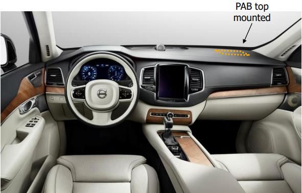
The passenger airbag (PAB) is situated into the dashboard (figure 3), and it is composed
of the bag unit, the gas generator with the explosive device, the housing, wire harness for
cables, and other minor parts for the assembly like bushings and nuts (figure 4), the product
does not include any electronic parts. The passenger airbag (PAB) studied in the Master Thesis,
is the frontal passenger airbag for the car model Volvo XC90.
Figure 3 Passenger airbag front side installed in the car’s dashboard
10The main parts of the airbag module (PAB) (figure 4) are the bag, the housing, the wire
harness and the inflator, other small parts are bushings, nuts, sealing cap and the label.
Airbag components
1 Inflator
2 Bag
3 Housing
4 Bushings
5 Sealing cap
6 Nuts
7 Label
8 Wire harness
Figure 4 Main components of a passenger
airbag
11Functional unit
The functional unit of the study is “one passenger airbag module (PAB)” and the
reference flow is “the total mass of one airbag module produced with all its parts”. This
functional unit was considered a good option because it is precisely defined (one module) and
measurable (the PAB module total weight is 1,99 kg). Moreover, "Airbags and Steering Wheel"
team is concerned about the sustainability aspects of the airbag, its components, and its entire
manufacturing process. Besides the fact that the PAB module is produced by one supplier, and
several components are produced in-house, making the task of gathering information easier.
System boundaries
The study included the acquisition of the raw materials, refining and manufacturing
processes, the technical boundaries include materials, energy, and transportation (inflows-
outflows) for the manufacture of the airbag components, the assembly of the module, and
transportation of the final product (PAB) to the Volvo factory in Gothenburg. A general
flowchart for the passenger airbag production with all its components is shown in figure 5, the
technical boundaries for the manufacturing of the airbag are delimited in red lines.
The geographical boundary is Europe, and the data collected is the suppliers’ current
production over one year.
The life cycle inventory will not include data from infrastructure and capital goods as
machinery or personnel food or transportation (Baumann & Tillman, 2004)
Figure 5 General flowchart for the airbag production.
12Choice of the impacts categories and method for impact assessment
The study focused in three environmental impact categories:
• Global warming potential (GWP 100 years)
• Abiotic resources depletion (ADP)
• Fresh Water Consumption
Global warming potential refers to greenhouse emissions that intensify the radiative forcing
in the atmosphere, that means these gases absorb infrared radiation and warms the atmosphere.
Carbon dioxide, methane, chlorofluorocarbons, and nitrous oxide are some of the gases in this
category that may cause climate change. (Baumann & Tillman, 2004). Global Warming
Potential was selected since the company intends to investigate the carbon footprint of their
products; therefore, it was the most relevant impact category for this study.
It is the company's purpose, in a near future, to continue expanding the study of
sustainability aspects of its products, that is why other impact categories were included in this
LCA study such as Abiotic Resource Depletion and Freshwater Consumption.
Abiotic Resource Depletion are physical non-living resources such as metals ore, crude oil,
wind energy production etc. and it is calculated in kg Antimony (Sb) equivalent. This model is
based on natural reserves of resources, that is the concentration of the elements in the earth
crust and the extraction rate of these resources (Leiden university, 2002). This impact category
has been included in the study with the objective to see how materials used in airbag production
affect the extraction and depletion of natural resources.
Due to problems associated with water scarcity, droughts and changing patterns of weather
and water due to the climate change, the use of freshwater in the airbag manufacturing was also
considered as an interesting topic to investigate.
The characterization methods chosen for the impacts assessment are CLM 2001 and Recipe
2016. CLM 2001 characterization methods is a quantitative method for impact assessment,
results are classified into midpoints categories based on common mechanisms for example
Global warming, Ecotoxicity etc. This method was developed by the Institute of Environmental
Sciences of Leiden University. (Sphera, 2022). Recipe LCA is a method for impact assessment
and was developed by RIVM, CLM, Pre consultants, Radboud University of Nijmegen and CE
Deft, this method is a fusion of two different methodologies as CML and Eco-indicator.
(Sphera, 2022).
Data collection
The data collection was mostly site-specific, one airbag supplier has contributed to the data
collection, and all the chain production has been investigated. General data was used for
information that was difficult to obtain, that the greatest possible resembled the origin of the
materials in terms of geography and time. An Excel-file, that can be found in appendix A, was
designed to collect site-specific data in order to cover the information that was necessary for
the study. General data was extracted from a recognized database as Sphera, and the
calculations have been made with the software program GaBi.
The first stage in the data gathering phase was to contact suppliers, which was done via
chat-conference, and it was explained the benefits of a LCA study. Secondly, the supplier
13company formed a team that had the task of handling contact with sub-suppliers so the data
collection could be obtained rapidly.
Some data was easy to collect, as for example for the manufacturing of the bag and the
inflator other data was difficult to obtain as for example the wire harness manufacturing, the
housing due to those productions taking place outside Europa.
Assumptions
The lack of site-specific data about some processes led to some assumptions, these
assumptions were considered as uncertainties.
The first assumption was with respect to the distance for the transportation of waste and
material to be recycled to its destination to municipal waste or recycling centres. The lack of
information led to the assumption that the distance to those places could be 50 km, later this
data was tested in the sensitivity analysis
Another assumption was with respect to the pyrotechnics in the inflator, since it was
confidential information, a similar chemical from general database was used in the modelling
of this process.
Since wire harness’ production takes place outside Europe, it was difficult to obtain
specific data regarding this production and the time constraints made it necessary to use generic
data. With specific data that suppliers provided, the model was built based on the materials and
weight of the wire harness components, and for upstream processes generic data was used.
Since upstream processes for the housing’s production also occur outside of Europe,
some assumptions had to be made in this case. In absence of generic data for the specific
geographic production, it was assumed that electricity played the biggest role in global
warming as an environmental impact during the life cycle of any product. Thereby, it has been
compared electricity production in different countries where general dataset for this process
existed, in order to choose the most suitable data for the production in question.
Limitations
Limitations arose because some data from upstream manufacturing processes was
difficult to collect. It was therefore necessary in some cases to make some assumptions, while
in others, data from general databases was used.
4 Inventory analysis
An inventory analysis was constructed using specific information about inflows and
outflows of all the materials, type and amount of energy, type of transportation, distance for
the transportation, countries of origin of the raw materials, manufacturing process for each of
the airbag’s components, and assembly of t airbag, all these information were provided by
suppliers. Generic data were used for processes for which site-specific data was not available.
Because of confidentiality concerns, detailed information, such as the amount of the raw
material, the countries from which the raw material was extracted, or in some cases upstream
processes couldn't be disclosed in this thesis. Accounting for the different types of emissions
generated by all these processes and the calculation of all the input and outputs were part of
the modelling in the LCA software program.
14Technical description of the processes and components
4.1 Bag
The bag is made of a woven fabric that can be made in different shapes depending on the
requirements of the vehicle. Fabrics used for airbags must resist the force of gases and must
not allow them to penetrate the fabric. Polyamide 6,6 high-tenacity multifilament fabric is
typically used for airbag’s cushions (Behera & Hari, 2010). The fabrics have different density
of the yarn (dtex), the designations dtex characterise the density of the yarn per dm2. The bag
is inflated by a mixture of gases, and it takes 37 milliseconds to be fully inflated, its function
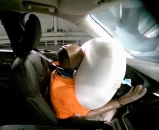
is protecting the passenger of serious injuries when a collision happens.
Figure 6 Driver’s airbag fully deployed (Euroncap, 2022)
Figure 7 Passenger and driver’s airbag fully deployed (Euroncap, 2022)
15Bag flowchart
Figure 8 Flowchart for the manufacturing of the bag
Raw materials and their manufacturing
Polyamide 6.6 is synthesised through polycondensation of
hexamethylenediamine (monomer) and adipic acid, which results in a chemical reaction that
creates polymers from monomers. During the manufacturing process, the polymer has a form
of a salt, this salt is heated until it becomes molten. The molten material is placed through a
metal spinneret, a process known as studding, a process that involves a large amount of water
and then the polymer is solidified. Afterward the material is spun into fibre, it is loaded onto a
bobbin, and stretched to increment its strength, then the material is wound in another bobbin,
once this is done, the fibre is prepared to be spun into a textile. Polyamide fibres require
between 7 and 8 MJ of energy per kilogram fiber (Swicofil, 2022), (Sphera, 2022)
Polyethylene terephthalate (PET) is other of the raw materials used in the manufacturing
of the bag; PET is produced in a vacuum by transesterifying dimethyl terephthalate (DMT)
with ethylene glycol as raw materials followed by a polycondensation reaction. The process
includes spinning of PET and surface treatment with epoxy resin sizing agent. PET fibers
require between 0.3 and 0.8 kilowatt hours per kilogram fiber. (Sphera, 2022). The data for
polyamide 6.6 and PET processes were gathered from the Sphera database.
16Bag’s manufacturing
The production of all the materials required for the fabrication of the bag takes place in
Europe and they are transported by trucks of 40 tons capacity to the assembly’s place. The
nylon fabric goes into the manufacturing in rolls of 1000 metres, shaped and measured
precisely with laser cutting and sewing to meet the desired requirements. Polyamide 6.6
fabrics’ waste from the production goes to recycling and PET waste from production goes to
incineration. Finally, the product undergoes quality control and after this the product is ready
for packaging and shipping to the airbag’s assembly place. This data was site-specific data and
was provided by suppliers.
4.2 Inflator
There are different types of inflators for airbags, one of these is the pyrotechnic inflator
which generates the gas through a chemical reaction. Other inflators have storage compressed
gas, and this gas is released to inflate the airbag. A third kind of inflator is a hybrid inflator,
this inflator uses a combination of gases and a solid material propellant that are stored in the
container, this was the inflator modelled in this LCA study. The initiator is activated in response
to a sensor that give a signal, the process starts when the propellants burn, the pressure of the
gases increases because of the high temperature in the chamber, and finally it escapes from the
outlets which are used to inflate the bag (United States Patentnr US5031932A, 1991).
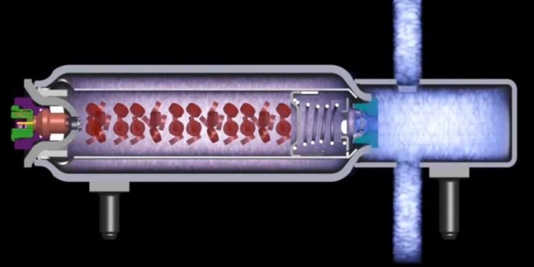
The following sequences of pictures were taken from a film provided by the supplier, to
demonstrate how the inflator activates.
Figure 9 Inflator filed with gases and propellant
17Figure 10: signal and ignition
Figure 11: the ignition of the propellants causes temperature and pressure increase
Figure 12: the gases release
18The bottle, the diffuser, and the combustion chambers, which are three of the major parts
of the inflator, are made of steel. There are other components such as gases like argon, helium
and oxygen, pyrotechnics and small parts made of plastic and steel. Site-specific data for all
the inflator components and their manufacturing processes (inflows and outflows) was
provided by the supplier, while general data sets were used for the upstream processes,
including steel, pyrotechnics, rubber, and gases' production.
Inflator Flowchart
Figure 13 Flowchart for the manufacturing of the inflator
Steel manufacturing
Steel is an iron alloy, this means that it is a metal that has been combined with at least
other metals or nonmetals elements, it is primarily composed of iron and contains no more than
2% carbon. The main raw materials in the production of the steel are iron ore, limestone, coal,
scrap, and energy. In a Sinter plant, the ore is crushed and mixed with the limestone coke
breeze, slag-forming agents etc. at elevate temperature. Steel can be produced via two main
routes: the blast furnace-basic oxygen furnace (BF-BOF) route and electric arc furnace (EAF)
route. The electrical arc furnace method uses mostly recycled steel that is melted by heating by
power electric arc, during this process different elements are added to reach the desired
properties of the steel as purity. In the blast furnace-basic oxygen furnace (BF-BOF) method,
the steel is made through oxidation by injecting oxygen. After this, a process called continuous
19casting takes place, steel is solidified, then the steel is cast in three semi-finished shapes: slabs,
billets, and blooms. (World Steel Association, 2017)
Gases (oxygen, argon, helium)
Cryogenic air fractionation is primarily performed with the LINDE process, Oxygen in
liquid state is produced by this process, the air is cooled under its critical point (Temperature
= 132,5 K, Pressure= 37,7 bar), when the air is cooled a separation by rectification take place,
in the rectification column the components of the air are separated by difference in their boiling
points. Separation of the different gases occur, the oxygen is extracted from the bottom of the
column, nitrogen from the top, and argon is taken from the middle of the column, the final
products are stored in gaseous state (Sphera, 2022).
Pyrotechnics
Pyrotechnics used in the inflator consist of a solid propellant, whose formulation was
part of the confidential information of the company and for that reason couldn’t be disclosed.
Because of confidentiality, one of the common chemicals used to produce explosives,
ammonium nitrate H4N2O3 was used during the modelling.
Ammonium nitrate is produced by the neutralisation of aqueous nitric acid by gaseous
ammonia, there are three main unit operations in the production process: 1. neutralisation, 2.
evaporation, 3. solidification (granulation). The first phase in the process is the neutralisation
reaction, this phase is highly exothermic. In the second phase, evaporation, a high-
concentration solution is formed, and the excess water is evaporated. Solidification, the final
phase, turns ammonium nitrate into granules (Sphera, 2022).
Rubber
The main material to produce rubber is tapped latex, this is extracted from plants that
contain this compound, there are between 30 and 40 percent rubber particles in latex, along
with 55 to 65% water, and small amounts of protein, sterol glycosides, resins, and ash (Sphera,
2022).
The process to produce rubber is a complex process, latex is obtained by cutting a
diagonal slice of bark halfway around the tree and approximately one third in thickness, and
the flowing latex is gathered in a collection container that will be emptied later. Water is
removed by centrifugal force or evaporation, elevating the rubber content to 60%, after this,
chemicals are added to the process with the objective of rubber particles reaching the surface.
The concentrate rubber is liquid form, which can be used for adhesives, coatings, and other
applications (Sphera, 2022)
Assembly of the inflator
After all the parts of the inflator are produced and transported to the assembly place, the
bottle, the combustion chamber, and the diffuser are welded, then propellant and gases are
added. When the parts have been assembled, the inflators move to packaging and shipping.
204.3 Housing
The housing is a rectangular plastic box, and its function is to contain the airbag and
retain the airbag in the adequate position for the inflation. The most used materials for its
fabrication are pressed metal or moulded plastic (United State Patentnr US 7,837,227B2 ,
2010).
The housing is made of a thermoplastic polypropylene (PP) reinforced with glass fiber,
the material is good against impact strength, stiffness, heat resistance, and it is a very good
material for injection moulding (Matmatch, 2022). Data collection for the housing’s production
was mainly site-specific data, the general data set was used for upstream processes as the
polypropylene and glass fibers’ production.
Polypropylene production
Polypropylene is a linear carbon, is a polyolefin or also called saturated polymer, the
main raw material to produce polypropylene is propene, propene is produced by cracking
naphtha from crude oil. Polypropylene is obtained through polymerization processes, there are
many different polymerization processes as solution polymerization, bulk polymerization, and
gas-phases processes. Heat and pressure are applied to propylene monomers along with a
catalyst system, during the polymerization process, relatively low temperatures and pressure
are applied, and the product obtained is translucent, but readily colorable. The properties of
plastic can be altered by altering the catalyst or production conditions (Sphera, 2022), (British
Plastics Federation, 2022)
Glass fibre production
Glass filaments fibres is a material widely used in a variety of applications, it is an
excellent material for reinforcement, thermal and electrical insulation among other
applications. (Wikipedia, 2022). The manufacturing of glass fibres generates a high amount of
waste per ton of product manufactured. Most of the water required for this process is for
cleaning and cooling, and the use of coating materials are responsible for the larger emissions.
The process is an energy- intensive process and requires high temperature, in continuous
manufacturing there are no recycling processes. The principal raw materials to produce glass
fibres are silica sand, alkali earth metals, carbonates and oxides, alumina, and boron. The
materials are smelted in cross-fired, air-fossil fuel or recuperative furnaces. During the glass
melting process, molten glass flows along refractory gas-heated canals to the forehearths. There
are several nozzles in the footplate of the bushing at the bottom of each forehearth that receive
the melted glass for fiberisation. A high-speed winding equipment diminishes the glass flowing
through the bushing and creates continuous filaments. After this, the filaments are cooled and
coated to obtain the desired properties of the filament to further applications (Sphera, 2022).
21Housing flowchart
Figure 14 Flowchart for the manufacturing of the housing
Polypropylene is a good material for injection moulding with a wide range of applications
(British Plastics Federation, 2022). Injection moulding is used to fabricate the airbag’s housing.
Plastic granules enter the machine and are transported and heated in a barrel. The molten plastic
is then injected into an empty cavity of the mould, where it solidifies in a few minutes before
the machine ejects the plastic part product (Todd, 1994)
4.4 Bushings
Bushings are small pieces which are used to screw the module into the car's instrument
panel; the raw material is steel, and the bushings are manufactured in Europe and transported
to another European city where the assembling fabric is situated.
The steel bar is cut and then the bushings are shaped in a lathe machine, this machine
rotates the pieces in axle until the bushing is formed, after pieces are controlled, they are
packaged and then shipped to assembly. Site specific data was used for the bushings’
production and generic data was used for the steel’s production.
22Bushing flowchart
Figure 15 Flowchart for the manufacturing of the bushings
4.5 Label
This manufacturing process has many steps, and they are performed by different actors:
the raw material used for the labels ‘fabrication is PET granulate. PET granulate are produced
from high purity ethylene glycol (EG) and Dimethyl terephthalate (DMT), (Valco group,
2021). The process consists of esterification, polymerization and palletization and
crystallization.
PET granulate is used to manufacture PET film by extrusion, after this, the films are
transported to the label manufacturing where the film is cut, put adhesive, and rolled. The rolls
are transported to the place where information is printed on the label. Because different stages
in this production were conducted for different suppliers, it was difficult to have detailed
information about all the steps in this manufacturing process for that reason general data was
used for this component.
23You can also read