CLMD16 16 Channel DC Load Controller Module - User's Manual
←
→
Page content transcription
If your browser does not render page correctly, please read the page content below
___________________________________________________________

                 CLMD16
   16 Channel DC Load Controller Module

                       User’s Manual

                              Revision 1.8

               Copyright ©2021 Carling Technologies, Inc.

                            60 Johnson Ave.
                        Plainville, CT 06062 USA

                          All Rights Reserved

                       http://www.maretron.com
___________________________________________________________

                                 Revision History
 Revision                                    Description
   1.0      Internal Review
   1.1      Internal Review
   1.2      Internal Review
   1.3      Revised “Features”
   1.4      Re-formatted document as necessary to render HTML version
   1.5      Added additional H-Bridge figures, Initial Release
   1.6      Corrected “J3” connector pin descriptions
   1.7      Added Revision History table, revised Footer styles, added new switching
            element quantities
   1.8      Added “Toggle Mode” Definition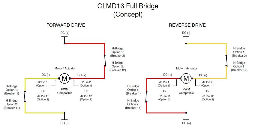
___________________________________________________________
                                                                                 Table of Contents
INTRODUCTION ...................................................................................................................................................... 1
  CLMD16 FEATURES ............................................................................................................................................................. 2
  THEORY OF OPERATION ......................................................................................................................................................... 3
CLMD 16 HARDWARE DESCRIPTION......................................................................................................................... 4
   Figure 1 - Hardware Description Front View ................................................................................................................ 4
   Figure 2 - Hardware Description Bottom View ............................................................................................................ 4
INSTALLATION ........................................................................................................................................................ 5
  UNPACKING THE BOX ............................................................................................................................................................ 5
  CHOOSING A MOUNTING LOCATION ........................................................................................................................................ 5
  MOUNTING THE CLMD16..................................................................................................................................................... 5
  CONNECTING THE CLMD16................................................................................................................................................... 5
    Figure 3 - Required Connections .................................................................................................................................. 6
  MAIN DC (+) CONNECTION ................................................................................................................................................... 7
    Table 1 - Main DC (+) Load Calculation Table Example ............................................................................................... 8
  MAIN DC (-) CONNECTION .................................................................................................................................................... 9
    Table 2 - Main DC (-) Cable Length Table..................................................................................................................... 9
  WIRING J1 – J3 CONNECTORS .............................................................................................................................................. 10
           Wiring a Harness Directly to J1-J3................................................................................................................................................................. 10
       Figure 4 - Required Deutsch Wire Crimping Tools...................................................................................................... 10
       Table 3 - Required Deutsch Plug Components ........................................................................................................... 11
           Connecting J1-J3 Using Maretron Accessory Cable Assemblies .................................................................................................................... 12
      Figure 5 - Accessory Cable Assemblies ....................................................................................................................... 12
      Figure 6 - Recommended Cable Assembly Connection Example................................................................................ 12
   “J1” (25 AMP BREAKER) POSITION DESCRIPTION .................................................................................................................... 13
      Table 4 - J1 Connector Pin Description ....................................................................................................................... 13
   “J2” (12 AMP BREAKER) POSITION DESCRIPTION .................................................................................................................... 13
      Table 5 - J2 Connector Pin Description ....................................................................................................................... 13
   “J3” (GENERAL PURPOSE / ANALOG) POSITION DESCRIPTION ................................................................................................... 14
      Table 6 - J3 Connector Pin Description ....................................................................................................................... 14
   CHECKING CONNECTIONS .................................................................................................................................................... 14
   NMEA 2000® CONNECTIONS.............................................................................................................................................. 15
      Figure 7 - NMEA 2000 Connectors ............................................................................................................................. 15
BREAKER (OUTPUT) FEATURES .............................................................................................................................. 16
  SOFT START ....................................................................................................................................................................... 16
    Figure 8 - Soft Start Voltage Ramp ............................................................................................................................ 16
  PULSE WIDTH MODULATION (PWM).................................................................................................................................... 16
  PARALLELING BREAKERS ...................................................................................................................................................... 17
    Figure 9 - Paralleled Breakers Connection Recommendation .................................................................................... 17
  HALF BRIDGE OPERATION .................................................................................................................................................... 18
  FULL BRIDGE OPERATION..................................................................................................................................................... 18
    Figure 10 - Full Bridge Operation Concept ................................................................................................................. 20
  LOAD SHEDDING ................................................................................................................................................................ 20
    Table 7 - Example of Load Shedding Priority Table .................................................................................................... 20
  OVERCURRENT PROTECTION ................................................................................................................................................. 21
    Figure 11 - Current vs Time Graph ............................................................................................................................. 22
  BINARY EVENT MONITOR..................................................................................................................................................... 22
    Figure 12 - Binary Event Monitor Hysteresis .............................................................................................................. 23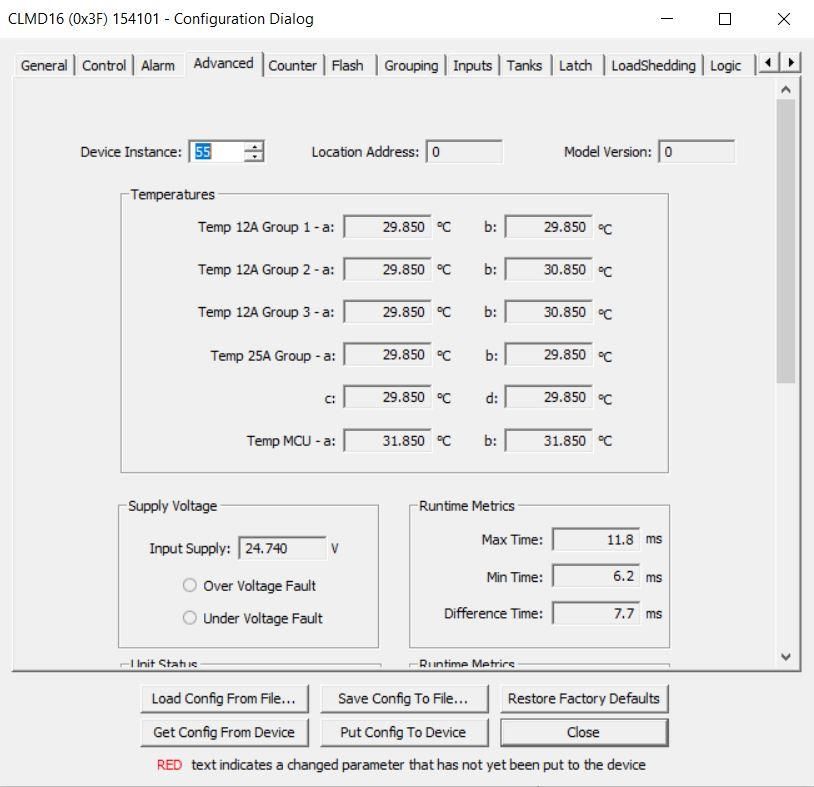
___________________________________________________________
SWITCHING APPLICATION ..................................................................................................................................... 24
  COUNTERS ........................................................................................................................................................................ 24
  TIMER DELAY ..................................................................................................................................................................... 26
  FLASH ............................................................................................................................................................................... 26
  LATCHES ........................................................................................................................................................................... 27
            Set/Reset Latch ............................................................................................................................................................................................. 28
     Table 8 - Latch Function Truth Table.......................................................................................................................... 28
   TOGGLE ............................................................................................................................................................................ 28
            Toggle Latch .................................................................................................................................................................................................. 28
       Table 9 - Toggle Function Truth Table ....................................................................................................................... 29
            Toggle Mode ................................................................................................................................................................................................. 29
   LOGIC ............................................................................................................................................................................... 29
     Table 10 - Logic Function Truth Table Example ......................................................................................................... 30
   ALARM OUTPUT ................................................................................................................................................................. 30
   AVAILABLE SIGNALS ............................................................................................................................................................ 31
     Table 11 - Available Signal Table ............................................................................................................................... 31
CONFIGURING THE CLMD16 .................................................................................................................................. 31
  GENERAL TAB .................................................................................................................................................................... 32
    Figure 13 - General Configuration Tab Dialog Box .................................................................................................... 32
       Label ............................................................................................................................................................................................................. 32
       Instance ........................................................................................................................................................................................................ 32
       Breaker #(n) .................................................................................................................................................................................................. 33
          Label......................................................................................................................................................................................................... 33
          State ......................................................................................................................................................................................................... 33
          Default State ............................................................................................................................................................................................ 33
          Default Lock State .................................................................................................................................................................................... 33
          Type ......................................................................................................................................................................................................... 33
          Current Rating .......................................................................................................................................................................................... 34
          Instantaneous Pickup ............................................................................................................................................................................... 34
          Short Time Pickup .................................................................................................................................................................................... 34
          Input Signal .............................................................................................................................................................................................. 34
          Toggle Mode ............................................................................................................................................................................................ 34
          PWM Counter .......................................................................................................................................................................................... 34
          Long Time Delay ....................................................................................................................................................................................... 34
       Voltage .......................................................................................................................................................................................................... 34
       Current .......................................................................................................................................................................................................... 35
       Status ............................................................................................................................................................................................................ 35
          Tripped ..................................................................................................................................................................................................... 35
          Thermal Protection .................................................................................................................................................................................. 35
          Load Shed................................................................................................................................................................................................. 35
          Hardware Fault ........................................................................................................................................................................................ 35
          Short To Ground....................................................................................................................................................................................... 35
          Short To Battery ....................................................................................................................................................................................... 35
          Over Current ............................................................................................................................................................................................ 35
          Open Circuit ............................................................................................................................................................................................. 36
          Breaker Locked ........................................................................................................................................................................................ 36
   CONTROL TAB .................................................................................................................................................................... 37
     Figure 14 - Control Tab Dialog Box ............................................................................................................................ 37
   ALARM TAB ....................................................................................................................................................................... 38
     Figure 15 - Alarm Configuration Tab Dialog Box ....................................................................................................... 38
         Alarm Enable Signal ................................................................................................................................................................................. 38
   ADVANCED TAB.................................................................................................................................................................. 39
       Figure 16 - Advanced Configuration Tab (Upper Portion) Dialog Box ....................................................................... 39
       Figure 17 - Advanced Configuration Tab (Lower Portion) Dialog Box ....................................................................... 40
            Device Instance ............................................................................................................................................................................................. 40
            Location Address........................................................................................................................................................................................... 40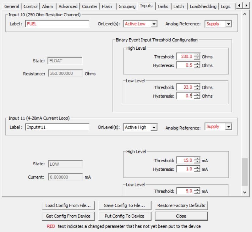
___________________________________________________________
    Model Version .............................................................................................................................................................................................. 41
    Temperatures ............................................................................................................................................................................................... 41
       Temp 12A Groups 1 to 3 .......................................................................................................................................................................... 41
       Temp 25A Group ...................................................................................................................................................................................... 41
       Temp MCU ............................................................................................................................................................................................... 41
    Supply Voltage .............................................................................................................................................................................................. 41
       Input Supply ............................................................................................................................................................................................. 41
       Over Voltage Fault ................................................................................................................................................................................... 41
       Under Voltage Fault ................................................................................................................................................................................. 41
    Execution Time Metrics ................................................................................................................................................................................ 41
       Max Time ................................................................................................................................................................................................. 41
       Min Time .................................................................................................................................................................................................. 41
       Difference Time........................................................................................................................................................................................ 41
    Unit Status .................................................................................................................................................................................................... 42
       Over Current Fault ................................................................................................................................................................................... 42
    Runtime Metrics ........................................................................................................................................................................................... 42
       Run Time .................................................................................................................................................................................................. 42
       Commissioned Time ................................................................................................................................................................................. 42
COUNTER TAB.................................................................................................................................................................... 43
    Figure 18 - Counter Configuration Tab Dialog Box .................................................................................................... 43
       Increment Signal ...................................................................................................................................................................................... 43
       Decrement Signal ..................................................................................................................................................................................... 44
       Reset Signal .............................................................................................................................................................................................. 44
       Counter Type ........................................................................................................................................................................................... 44
       Min Set Point............................................................................................................................................................................................ 45
       Max Set Point ........................................................................................................................................................................................... 45
       Press Step Size.......................................................................................................................................................................................... 45
       Hold Step Size .......................................................................................................................................................................................... 45
       Hold Step Time ......................................................................................................................................................................................... 45
       Hold Period .............................................................................................................................................................................................. 45
       Active Threshold ...................................................................................................................................................................................... 45
FLASH TAB ........................................................................................................................................................................ 46
    Figure 19 - Flash Configuration Tab Dialog Box ......................................................................................................... 46
      On Period ................................................................................................................................................................................................. 46
      Off Period ................................................................................................................................................................................................. 46
      Number of Cycles ..................................................................................................................................................................................... 47
      Enable Signal ............................................................................................................................................................................................ 47
GROUPING TAB .................................................................................................................................................................. 47
    Figure 20 - Grouping Configuration Tab Dialog Box .................................................................................................. 47
     Groups 1 through 4 ....................................................................................................................................................................................... 48
        Group 1 .................................................................................................................................................................................................... 48
        Group 2 .................................................................................................................................................................................................... 48
        Group 3 .................................................................................................................................................................................................... 48
        Group 4 .................................................................................................................................................................................................... 48
INPUTS TAB ....................................................................................................................................................................... 49
    Figure 21 - Inputs Configuration Tab (Active High/ Low/ Float Channels) Dialog Box .............................................. 49
    Figure 22 - Inputs Configuration Tab (Resistive Input and Current Loop Channels Dialog Box) ................................ 50
    Input # (n) ..................................................................................................................................................................................................... 50
       Label......................................................................................................................................................................................................... 50
       On Level(s) ............................................................................................................................................................................................... 50
       Analog Reference ..................................................................................................................................................................................... 51
       State ......................................................................................................................................................................................................... 51
       Voltage/Resistance/Current .................................................................................................................................................................... 51
       High Threshold ......................................................................................................................................................................................... 51
       High Hysteresis......................................................................................................................................................................................... 51
       Low Threshold .......................................................................................................................................................................................... 51
       Low Hysteresis ......................................................................................................................................................................................... 52
TANKS TAB ........................................................................................................................................................................ 52
    Figure 23 - Tanks Configuration Tab Dialog Box ........................................................................................................ 52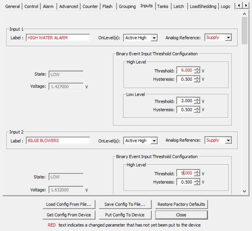
___________________________________________________________
Enable ...................................................................................................................................................................................................... 53
Label......................................................................................................................................................................................................... 53
Pressure ................................................................................................................................................................................................... 53
Tank Capacity ........................................................................................................................................................................................... 53
Tank Number ........................................................................................................................................................................................... 53
Tank Type ................................................................................................................................................................................................. 53
Data Damping Period ............................................................................................................................................................................... 54
Realtime Resistance ................................................................................................................................................................................. 54
Realtime Current ...................................................................................................................................................................................... 54
TANK LEVELS CALIBRATION .................................................................................................................................................. 54
Manual Table ................................................................................................................................................................................................ 54
Figure 24 - Current Loop Manual Table Calibration Tank, Initial Window Dialog Box .............................................. 55
Fluid Density ............................................................................................................................................................................................ 55
Number of Table Entries .......................................................................................................................................................................... 55
Current Tank Calibration .......................................................................................................................................................................... 55
Step Fill Table ................................................................................................................................................................................................ 55
Figure 25 - Current Loop Step Fill Calibration Tank, Initial Window Dialog Box ........................................................ 56
Figure 26 - Current Loop Step Fill Tank Calibration Dialog Box ................................................................................. 57
Figure 27 - Current Loop Tank Fill Confirmation Dialog Box ...................................................................................... 57
LATCH TAB ........................................................................................................................................................................ 58
Figure 28 - Latch Configuration Tab Dialog Box ........................................................................................................ 58
Set Signal .................................................................................................................................................................................................. 58
Reset Signal .............................................................................................................................................................................................. 58
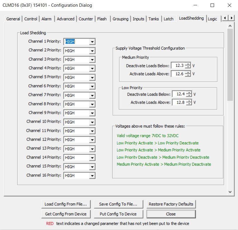
LOAD SHEDDING TAB .......................................................................................................................................................... 59
Figure 29 - Load Shedding Configuration Tab Dialog Box.......................................................................................... 59
Channel (x) Priority .................................................................................................................................................................................. 59
Medium Priority Deactivate Loads Below ................................................................................................................................................ 59
Medium Priority Activate Loads Above .................................................................................................................................................... 60
Low Priority Deactivate Loads Below ....................................................................................................................................................... 60
Low Priority Active Loads Above .............................................................................................................................................................. 60
Voltages above must follow these rules .................................................................................................................................................. 60
LOGIC TAB......................................................................................................................................................................... 61
Figure 30- Logic Confirmation Tab Dialog Box........................................................................................................... 61
Input A ..................................................................................................................................................................................................... 62
Input B...................................................................................................................................................................................................... 62
Input C ...................................................................................................................................................................................................... 62
Lookup Table ............................................................................................................................................................................................ 62
TIMER TAB ........................................................................................................................................................................ 63
Figure 31 - Timer Configuration Tab Dialog Box ........................................................................................................ 63
Delay Signal .............................................................................................................................................................................................. 63
Delay Type................................................................................................................................................................................................ 64
Delay Time ............................................................................................................................................................................................... 64
TOGGLE TAB ...................................................................................................................................................................... 65
Figure 32 - Toggle Configuration Tab Dialog Box ...................................................................................................... 65
Toggle Signal ............................................................................................................................................................................................ 65
DISCRETE I/O TAB .............................................................................................................................................................. 66
Figure 33 - Discrete I/O Configuration Tab Dialog Box .............................................................................................. 66
Data Instance ........................................................................................................................................................................................... 66
Indicator ................................................................................................................................................................................................... 67
INSTALLATION DESCRIPTION TAB ........................................................................................................................................... 67
Figure 34 - Installation Description Tab Dialog Box ................................................................................................... 67
OPERATING THE CLMD16 ...................................................................................................................................... 68
LED INDICATORS ................................................................................................................................................................ 68
DIAG ............................................................................................................................................................................... 68
CAN-A ............................................................................................................................................................................. 68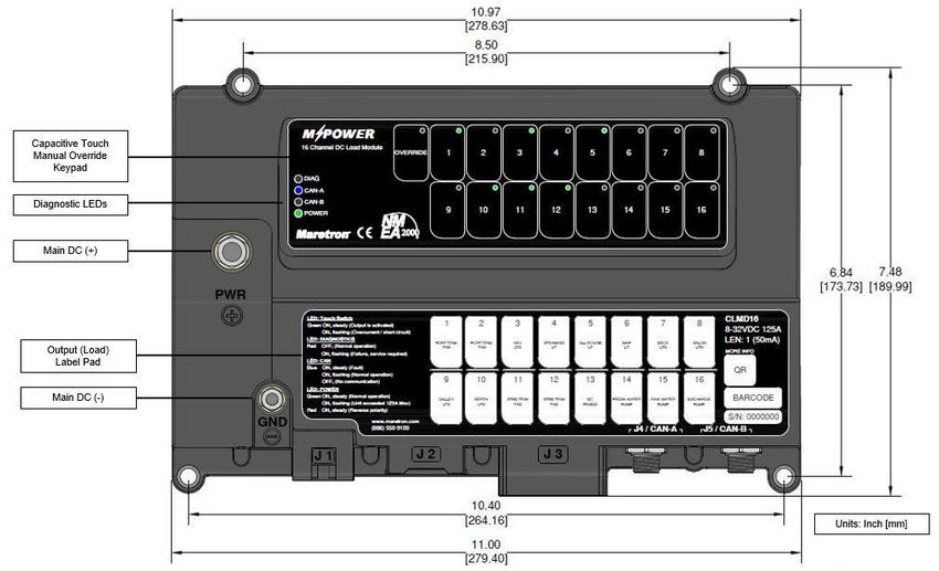
___________________________________________________________
   CAN-B ............................................................................................................................................................................. 68
   POWER ........................................................................................................................................................................... 68
   BREAKER STATUS LED INDICATORS........................................................................................................................................ 69
   OVERRIDE SWITCHES........................................................................................................................................................... 69
MAINTENANCE ..................................................................................................................................................... 70
TROUBLESHOOTING .............................................................................................................................................. 70
   Table 12 - Troubleshooting Symptoms and Check Procedure .................................................................................... 70
TECHNICAL SPECIFICATIONS .................................................................................................................................. 72
  CERTIFICATIONS ................................................................................................................................................................. 72
  NMEA 2000® PARAMETER GROUP NUMBERS (PGNS) ........................................................................................................... 72
   ELECTRICAL........................................................................................................................................................................ 73
   MECHANICAL ..................................................................................................................................................................... 73
   ENVIRONMENTAL ............................................................................................................................................................... 74
   ENVIRONMENTAL TESTING ................................................................................................................................................... 74
TECHNICAL SUPPORT ............................................................................................................................................ 75
    Figure 35 - Product Manual QR Code ......................................................................................................................... 75
MARETRON (2 YEAR) LIMITEDWARRANTY ............................................................................................................. 75
 WARRANTY RETURN PROCEDURE:......................................................................................................................................... 76
APPENDIX A – NMEA 2000® INTERFACING .............................................................................................................. 77
  CLMD16 NMEA 2000® PERIODIC DATA TRANSMITTED PGNS ................................................................................................. 77
  PGN 127500 – LOAD CONTROLLER CONNECTION STATE/CONTROL .......................................................................................... 77
  PGN 127501 – BINARY STATUS REPORT ............................................................................................................................... 77
  PGN 130314 – ACTUAL PRESSURE ...................................................................................................................................... 78
  PGN 127505 – FLUID LEVEL ............................................................................................................................................... 78
  PGN 127751 – DC VOLTAGE/CURRENT ............................................................................................................................... 79

Table of Appendices:
Appendix A – NMEA 2000®
Interfacing……………………………………………………………………………………….……………77

Notices:
 All illustrations are for reference purposes only. Nothing contained in this document shall replace or
 modify the requirements of industry standards applicable to wire or other protection, including
 without limitation, those of the American Boat and Yacht Council (ABYC), the National Electric
 Code (NEC), and/or the National Fire Protection Association (NFPA). Failure to install the device or
 any components thereof in compliance with any such Industry Standard may limit the warranties
 made by Carling Technologies, Inc.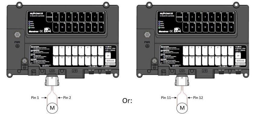
___________________________________________________________
        WARNING
         • Tampering with the CLMD16 including removal of the CLMD16 cover
           will compromise the operation of the unit and voids warranties set forth
           by Carling Technologies.
         • Please ensure that you read and understand this manual before
           undertaking installation and use.
         • The CLMD16 must be wired in accordance with standards set forth by
           ABYC and other applicable agencies.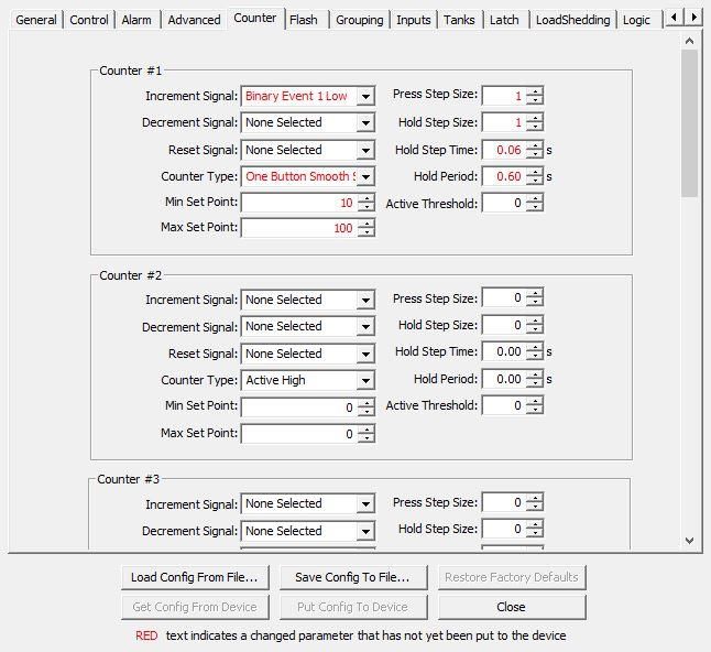
CLMD16 User’s Manual                                                                                 __

                                          Introduction
Congratulations on your purchase of the Maretron MPower® CLMD16, 16 Channel DC Load
Controller Module. Carling Technologies has designed and built your CLMD16 to the highest
standards for years of dependable and accurate service.

The Maretron CLMD16 contains 16 output channels implemented by direct current (DC) Electronic
Circuit Breakers (ECB’s). Twelve breakers can switch up to 12 Amps, and four breakers can switch
up 25 Amps, with a total current capacity of 125 Amps. In addition to fast switching, low-loss solid
state ON/OFF switches, it provides accurate current measurement for each load as well as short
circuit protection. Certain breakers can be programmed to operate in half-bridge or full-bridge mode,
making them ideal for control of electric motors where a reversing polarity function is needed.

The CLMD16 additionally contains 8 input channels programmable to sense whether the input is
connected to DC (+), DC (-), or connected to neither. The CLMD16 also contains two resistive input
channels (250Ω and 1KΩ) and a single 4-20mA current loop input channel which could be used for
indication of tank levels. The CLMD16 supplies a set of output terminals which can be connected to
an external alarm light or sounder which can be activated under a wide variety of conditions.
Additionally, the CLMD16 contains 4 input channels separate from other inputs reserved for digital
addressing or future expansion of input capability.

The CLMD16 connects directly to one or two NMEA 2000® networks so you can control the
breakers from any device running Maretron N2KView® software, such as TSM-Series multifunction
displays or MBB-Series black boxes. Breakers may also be controlled directly from a VMM Switch
or CKM keypad, or any other device transmitting the NMEA Binary Status Report PGN (127501)
Additionally, since the CLMD16 supports standard NMEA 2000® messages for control, it can be
controlled by many third-party multi-function displays.

The CLMD16 handles resistive DC loads like lights or inductive DC loads like pumps and motors as
well as capacitive loads. An added benefit of the CLMD16 is that it reports the current through each
of the 16 breakers. This allows you to determine if loads are drawing too little electrical current such
as burnt-out bulbs, or if the loads are starting to draw too much electrical current.

The Maretron CLMD16 is designed to operate within the harsh demands of the marine environment.
However, no piece of marine electronic equipment can function properly unless installed, configured,
and maintained in the correct manner. Please read carefully and follow these instructions for
installation, configuration, and usage of the Maretron CLMD16 to ensure optimal performance.

1                                                              CLMD16 User’s Manual Rev. 1.8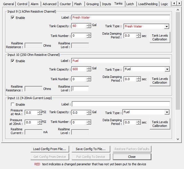
___________________________________________________________

                                     CLMD16 Features
Features:
   • 16 Total Output Breakers
          o 12x12A, 4x25A Breaker Maximum Current Ratings (resistive, capacitive, and inductive
            load capable)
          o Short Circuit Protected
          o Up to 32VDC Switching Voltage
          o Voltage back feed protection (back-to-back Field Effect Transistor (FET)) for all power
            outputs
          o All Breaker Outputs Support Soft Start
          o Parallel Breaker Capability. (4 Groups, each group can have up to 2 breakers)
          o PWM on all breaker Outputs (frequency 200Hz on Breakers 3-10,11,12 and 2kHz on
            Breakers 1,2)
          o Current Measurement on all Breaker Outputs
            (accuracy is ± 0.5 Amps at 0.1 Amp resolution)
          o Four (4) half-bridge 12 Amps breakers: (shared output with 4 high-side 12 Amp
            breakers)
          o Two (2) half-bridge (Breaker 1 & Breaker 2) outputs with PWM.
          o Two (2) full-bridge (H-bridge) channel (utilizing 2 half-bridge output breakers 1 and 2,
            or 11 and 12)

   •   125A Maximum Unit Current Capacity
   •   Capacitive Touch Switches for local override control of all loads
   •   Eight (8) Analog (VDC) / Digital Inputs (DC (-), DC (+) or “Float” sensing inputs)
   •   Two (2) Resistive Inputs (0 to 250 Ω) & (0 to 1000 Ω)
   •   One (1) Current Input (4 to 20 mA Current Loop)
   •   All inputs protected against short to Power and short to Ground
   •   Alarm output (switched power and ground (12 or 24 VDC))
   •   Dual Optically Isolated Controller Networks (CAN) over NMEA 2000 for zero potential of
       ground loops and redundant communication ability
   •   Ignition Protected Sealed Waterproof Enclosure and Connectors - Ingress Protection IP67
   •   Voltage Input: 8 to 32 VDC (reverse polarity protected)
   •   Power Stud: 125 DC Amps max current capacity, continuous @ 70°C
   •   Ground Stud: 25 DC Amps max current capacity
   •   Operating Temp: -30°C to 70°C
   •   Four (4) Address-input lines (Active Low, For Future Use)

For Technical Specifications please refer to page 72.

CLMD16 User’s Manual Rev. 1.8                                                                     2
You can also read